Abstract
Carbon nanotubes were employed as adhesive reinforcement/nano-stitches to aluminum bonded joints. The CNT addition to an epoxy adhesive not only lead to an increase on load capacity but it is also the most probable cause of the mixed failure mode (adhe-sive/cohesive). The damage evolution was described as the stiff-ness decrease and the failure mixed modes were related to the load capacity. Although the presence of CNT cluster were observed, in small concentrations (< 1.0 wt. %), these clusters acted as crack stoppers and lead to an increase on lap joint shear strength. The addition of 2.0 wt. % carbon nanotubes lead to an increase on load capacity of approximately 116.2 % when the results were compared against the single lap joints without carbon nanotubes.
Keywords
Carbon nanotubes, bonded joints, hybrid joints, experimental me-chanics, failure modes
Bonded Joints with “Nano-Stitches”: Effect of Carbon
Nanotubes on Load Capacity and Failure Modes
1 INTRODUCTION
As discussed by Chaves et al (2014), adhesive joints are among the most used techniques in modern structural components nowadays. The reasons are based on cost-effectiveness and load capacity increasing without creating local stress concentrations. Liu et al (2014) pointed out that, bonded joints are expanding their range of applications from traditional civil and mechanical engineering areas to microelectronics and aerospace applications, e.g. satellites and unmanned air vehicles. For these new areas of applications, in addition to load capacity requirement, weight is another im-portant issue. To be able to optimize, or at least decrease the bonded joint weight considerably, modeling and experimental approaches are the most common tools employed. The failure analysis performed by da Costa Mattos et al (2012), the experimental analysis on different types of joints done by Li et al (2015) and da Silva and Campilho (2012) where a comprehensive review on
nu-Henrique N. P. Oliva a
Antonio F. Avila b
a Universidade Federal de Minas Gerais,
Graduate Studies Program in Mechanical Engineering, 6627 Antonio Carlos Avenue, Belo Horizonte, Brazil MG 31270-901, e-mail: [email protected]
b Universidade Federal de Minas Gerais,
Mechanical Engineering Department, 6627 Antonio Carlos Avenue, Belo Horizonte, Brazil MG 31270-901, e-mail: [email protected]
http://dx.doi.org/10.1590/1679-78253348
merical modeling of adhesive joints was considered are among the most effective research papers on bonded joints. A different approach considering weight/load capacity was proposed by Avila and Bueno (2004), Turaga and Sun (2008) and Kumar et al (2010). In their case, the bonded joint de-sign was changed, Avila and Bueno (2004) used wavy-lap joints, Turaga and Sun (2008) used sin-gle-lap joints with attachments and Kumar et al (2010) added bolts in addition to using attach-ments, which lead to increase on load capacity close to 41%, 60% and 80%, respectively. In all cases, the load path was changed, in the case of Avila and Bueno, by creating the wavy bonded shape, while Turaga and Sun (2008) and Kumar et al (2010) focused on additional elements to create new load paths. Unfortunately, the issue of weight was not solved, even though the load capacity was greatly improved. To be able to address the issue of weight optimization with improvement on load capacity, new paradigm must be introduced. This new paradigm is the usage of nanostructures. As shown by Wu et al (2015), carbon based nanostructures, i.e. graphene and carbon nanotubes, are the most promising nanostructures for epoxy mechanical and/or electrical properties improvement. Notice that epoxy systems are among the most used adhesives employed for engineering applica-tions. The usage of functionalized carbon nanotubes (CNT) for improving bonded joints were inves-tigated by Sydlik et al (2013). They were able to improve the load capacity (lap shear strength) by 50% by adding 1 wt. % of carbon nanotubes over the unmodified adhesive. Korayem et al (2016) proved that CNT-epoxy compared to neat epoxy could provide significant increase of bond strength at moderately elevated temperatures and they have tested it for carbon fibre reinforced polymer laminates and steel. The authors found an improvement of the glass transition temperature of 30% for the addition of 3 wt.% CNTs to the epoxy. The CNT functionalization, however, is a very ag-gressive procedure due to usage of strong acids, i.e. sulfuric and nitric acids, which introduces a large number of defects into the CNTs and lead to environmental problems. Therefore, this research focuses on dispersion of non-functionalized/as grown CNT into epoxy/adhesive systems for bonded joint shear lap strength improvement.
2 MATERIALS AND EXPERIMENTAL PROCEDURES
The bonded joint used in this research is a single lap joint and follows the ASTM standard D 1002-10 (2010), see Figure 1 for more details. To be able to have a near optimum adhesive thick-ness, the methodology proposed by da Silva et al (2006) was employed. According to them, the 0.15 mm adhesive thickness is the most effective thickness for aluminum adherents and epoxy systems. To be able to investigate the nanostructures formed during the CNT dispersion an atomic force microscopy analysis was performed using an Asylum Research - MFP-3D microscope.
Figure 1: Single lap joint dimensions in millimeters.
3 RESULTS
3.1 Bonded Joints without Carbon Nanotubes
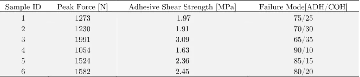
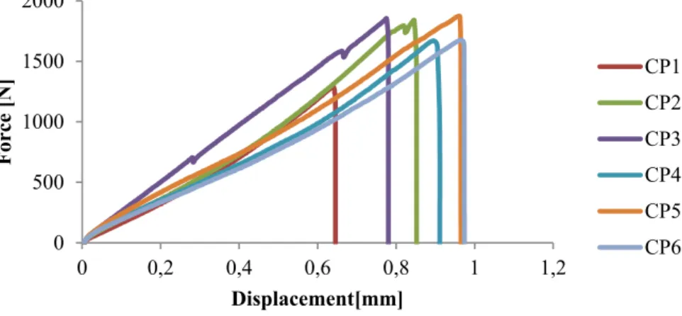
Although the theory proposed by Hart-Smith (1983) had predicted the adhesive failure (ADH) as the main failure mode, a mixed mode was observed for the single lap joint group without carbon nanotubes. The ratio between the two failure modes, adhesive (ADH) and cohesive (COH), ranged by 90/10 to 65/35, see Table 1. The load capacity seems to be related to these ratios, as the COH’s area increases there is a growth on load capacity. Furthermore, an increase on elongation was also observed. This phenomenon can be related to the adhesive yielding and damage growth. The dam-age growth was modeled by Masmanidis and Philippidis (2015) and related to the stiffness decrease. According to them, as damage evolves, the stiffness decreases at same ratio. As it can be observed in Figure 2, sample #3 has a significant decrease on stiffness, which is an indication on damage evolution. This damage evolution, however, is gradual which allows the energy dissipation and con-sequently a much higher peak load. When sample #4 is analyzed, the behavior is the opposite. The sharp increase on stiffness lead to small elongation at failure. This phenomenon can be explained by the adhesive thickness at the joint end. According to Kim (2003), the adhesive shear strength, also referred as load capacity, is affected by the adhesive bond line thickness at the joint end. A small thickness at the joint end lead to a harsh increase on peel and shear stresses at this region and con-sequently damage initiation and propagation at high speed. By observing sample #4 thickness at upper right end (see Figure 3 D), it can be noticed a thickness around 0.10 mm.
Sample ID Peak Force [N] Adhesive Shear Strength [MPa] Failure Mode[ADH/COH]
1 1273 1.97 75/25
2 1230 1.91 70/30
3 1991 3.09 65/35
4 1054 1.63 90/10
5 1524 2.36 85/15
6 1582 2.45 80/20
Figure 2: Force-displacement curves – group #1 no CNT addition.
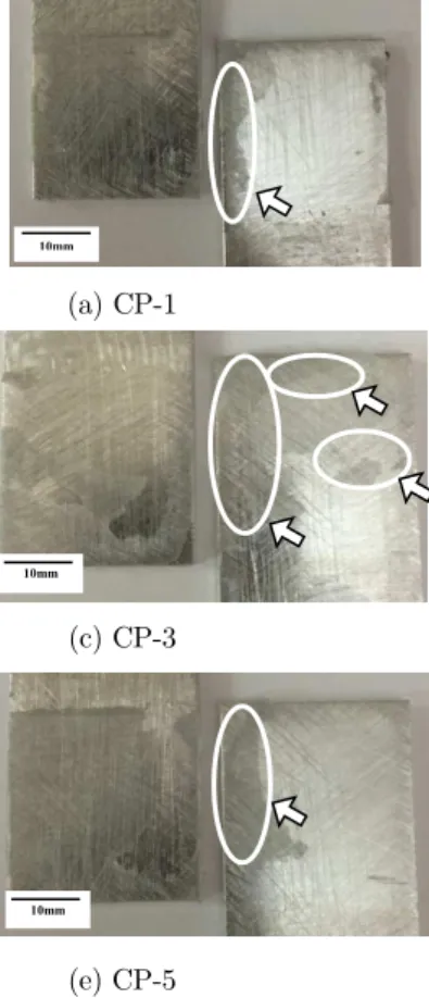
(a) CP-1 (b) CP-2
(c) CP-3 (d) CP-4
(e) CP-5 (f) CP-6
Figure 3: Failure modes – group #1 no CNT addition.
3.2 Bonded joints with 0.5 wt. % of carbon nanotubes
Table 2 summaries the main data obtained during the tensile test of this group of single lap joints. The average load capacity with 0.5 wt. % CNT is 17.87% higher than the ones without CNT. The ratio between ADH/COH shows a correlation between the increase on COH failure mode and the
0 500 1000 1500 2000 2500
0 0,5 1 1,5
Force [N]
Displacement [mm]
CP1 CP2 CP3 CP4 CP5 CP6
10mm
10mm
10mm
10mm
peak force at failure. Moreover, as discussed by Sydlik et al (2013), the addition of CNT to the ad-hesive lead to an increase on bonded joint overall stiffness. The damage propagation, however, seems to be less noticeable, as the decrease on stiffness is much smaller (see Figure 4). A possible hypothesis for such behavior is CNT presence, which acts as barrier against the crack propagation inside the adhesive (see Figure 5 – AFM observation). By performing an AFM analysis, it was pos-sible to identify CNT clusters. The dark points shown in Figure 6A-F seem to be the macroscopy representation of such cluster, which can make the crack propagation even harder. Notice that ac-cording to Avila et al (2014), CNTs have a stiffness close to 1.0 TPa and ultimate strength around 60 GPa. The increase on cohesive failure mode (COH) can be also explained by the increase on interface adherent/adhesive strength provided by the CNTs.
Sample ID Peak Force [N] Adhesive Shear Strength [MPa] Failure Mode [ADH/COH]
1 1295 2.01 95/05
2 1840 2.85 85/15
3 1853 2.87 70/30
4 1669 2.59 90/10
5 1869 2.90 60/40
6 1676 2.60 90/10
Table 2: Group #2 summary – 0.5 wt. % CNT addition.
Figure 4: Force-displacement curves – group #2 – 0.5 wt. % CNT addition.
Figure 5: AFM observation – 0.5 wt. % CNT. 0
500 1000 1500 2000
0 0,2 0,4 0,6 0,8 1 1,2
Force [N]
Displacement[mm]
(a) CP-1 (b) CP-2
(c) CP-3 (d) CP-4
(e) CP-5 (f) CP-6
Figure 6: Failure modes – group #2 – 0.5 wt. % CNT addition.
3.3 Bonded Joints with 1.0 wt. % of Carbon Nanotubes
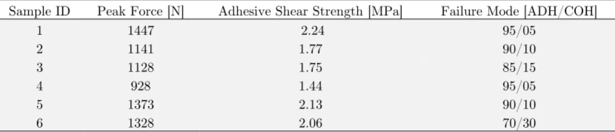
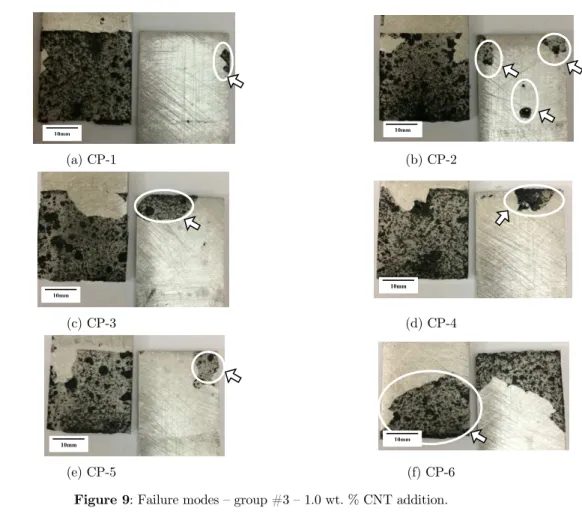
It was expected that with the increase on carbon nanotubes quantities the load capacity will also increase. However, this predicted behavior based on rule of mixtures (Jones, 1999), was not estab-lished. As it can be observed in Table 3, the load capacity was reduced when compared against the previous group. One hypothesis for such behavior is the formation of large CNT clusters, which create stress concentration regions. The damage propagation was also affected by these large clus-ters. As it can be noticed in Figure 7, a stiffness decrease with the elongation was observed. Accord-ing to Masmanidis and Philippidis (2015), the damage propagation has direct influence on stiffness changes during the tensile test of single lap joints. As noticed in Figure 8, the cluster formation seems to be aligned and with much larger agglomeration, which can be translated as stress concen-tration spots. Finally, by observing Figures 9A-F, it is possible to spot “dark dots” inside the failure area. These “dark dots” are the macroscopic representation of those CNT clusters observed at AFM analysis. The reason for such cluster formation can be attributed to the CNT dispersion process. Unfortunately, as the dispersion process is not homogeneous, the stress concentration generated could be the reason for such decrease on load capacity, as the number of crack formation is much higher.
10mm 10mm
10mm
10mm
10mm
Sample ID Peak Force [N] Adhesive Shear Strength [MPa] Failure Mode [ADH/COH]
1 1447 2.24 95/05
2 1141 1.77 90/10
3 1128 1.75 85/15
4 928 1.44 95/05
5 1373 2.13 90/10
6 1328 2.06 70/30
Table 3: Group #3 summary – 1.0 wt. % CNT addition.
Figure 7: Force-displacement curves – group #3 – 1.0 wt. % CNT addition.
Figure 8: AFM observation – 1.0 wt. % CNT.
3.4 Bonded Joints with 2.0 wt. % of Carbon Nanotubes
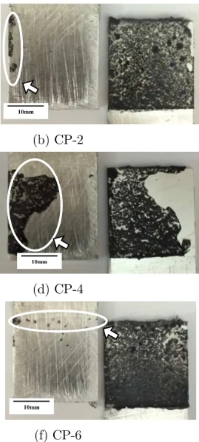
This group represents the highest increase on load capacity (see Table 4). However, as shown in Figure 10, two different sub-groups can be identified. As the load capacity for each sub-group is different, i.e. for sub-group #1 the average peak force at failure is 3118 N while for sub-group #2 the average value is 5223 N, it is possible to suppose that another mechanism for increasing load capacity is acting in addition to the increase on stiffness provided by the CNT dispersion. Figure 11 shows the AFM observation of the CNT cluster formed, which is much more homogeneous and uniformly distributed. The same pattern can be observed at macroscopic level when Figures 12A-F were analyzed. By analyzing the specimen’s photos before each test, it was possible to identify some additional material around the end joint edges. This additional material is defined by da Silva
0 500 1000 1500 2000
0 0,2 0,4 0,6 0,8 1
Force [N]
Displacement [mm]
and Campilho (2012) as tapering. Moreover, according to them, the tapering effect is to improve the bonded joint load capacity. By measuring the additional area provided by the tapering, it is possible to establish a correlation between the increase on load capacity due to the CNT addition and the additional increase due to tapering. The average increase on load capacity when the 2.0 wt. % CNT samples were compared against the blank (no CNT) samples is around 116.2%. The taper-ing provided an additional 67.5 % increase on load capacity, which is equivalent to an increase on load capacity with respect to the blank specimens around 262.2 %. According to da Silva and Ochsiner (2008), the tapering, also referred to as spew filet, lead to a load transfer through this additional materials, which makes the peel and shear stresses at joint end decrease. This decrease on peel and shear stresses allow the load capacity to grow before the failure.
(a) CP-1 (b) CP-2
(c) CP-3 (d) CP-4
(e) CP-5 (f) CP-6
Figure 9: Failure modes – group #3 – 1.0 wt. % CNT addition.
Sample ID Peak Force [N] Adhesive Shear Strength [MPa] Failure Mode [ADH/COH]
1 4285 6.64 95/05
2 5371 8.33 95/05
3 6012 9.32 95/05
4 2806 4.35 80/20
5 3718 5.76 90/10
6 2829 4.38 95/05
Table 4: Group #4 summary – 2.0 wt. % CNT addition.
10mm 10mm
10mm
10mm
Figure 10: Force-displacement curves – group #4 – 2.0 wt. % CNT addition.
Figure 11: AFM observation – 2.0 wt. % CNT.
(a) CP-1 (b) CP-2
(c) CP-3 (d) CP-4
(e) CP-5 (f) CP-6
Figure 12: Failure modes – group #4 – 2.0 wt. % CNT addition. 0
1000 2000 3000 4000 5000 6000 7000
0 1 2 3
Force [N]
Displacement [mm]
CP1 CP2 CP3 CP4 CP5 CP6
10mm 10mm
10mm 10mm
4 CONCLUSIONS
Carbon nanotubes were employed as adhesive reinforcement/nano-stitches to aluminum bonded joints. The CNT addition to an epoxy adhesive not only lead to an increase on load capacity but it is also the most probable cause of the mix failure mode (adhesive/cohesive). The experimental work was conducted as recommended in the literature and the microscopic observations allowed a better understanding of the phenomena observed macroscopically in relation to the homogeneity and char-acteristics of the adhesive area. According to the results obtained, it was noticed that the addition of carbon nanotubes improved the resistance in the adhesive-adherent interface. The observed im-provement was more evident for the sets with better dispersion and distribution of the CNT in their failure modes (as an example, group #4 of the bonded joints in Figure 11). On the other hand, the addition of CNT in large quantities, with a poor dispersion, caused stress concentration, due to the presence of clusters. The damage evolution was described as the stiffness decrease and the failure mixed modes were related to the load capacity. The addition of 2.0 wt. % carbon nanotubes lead to an increase on load capacity of approximately 116.2 % when the results were compared against the single lap joints without carbon nanotubes.
Acknowledgments
The authors would like to acknowledge the financial support provided by the Brazilian Research Council, grant 304646/2014-8 and the Air Force Office of Scientific Research grant FA9550-14-1-0377. The first author would like to acknowledge the financial support provided by the Graduate Studies Program in Mechanical Engineering (PPGMEC) from Universidade Federal de Minas Ge-rais through a fellowship via CAPES foundation. The authors are grateful to the UFMG’s Centre of Microscopy and Microanalysis for the technical support.
References
ASTM D 1002. (2010) Standard test method for apparent shear strength of single-lap-joint adhesively bonded metal specimens by tension loading (metal-to-metal). ASTM International 15-6:1-6.
Ávila, A.F., Bueno, P.O. (2004) Stress analysis on a wavy-lap bonded joint for composites. International Journal of Adhesion and Adhesives 24:407-414.
Ávila, A.F., da Cruz, D.T.L., Nascimento Jr., H. Vidal, F.A.C. (2016). Graphene Based Hybrid Composites. In: Graphene Science Handbook. CRC Press, Taylor & Francis Group. Chapter 32, 510-524.
Ávila, A.F., Munhoz, V.C., Oliveira, A.M., Monteiro, E.C. (2014). Carbon based nanostructures hybrids for compo-site materials: The graphene – carbon nanotube interaction investigation. Journal of Multifunctional Materials, 2:195-206.
Barracuda Advanced Composites. (2015) AR300/AH30-150 Epoxy Systems Data sheet.
Chaves, F.J.P., da Silva, L.F.M., de Moura, M.F.S.F., Dillard, D.A., Esteves, V.H.C. (2014). Fracture mechanics tests in adhesively bonded joints: A literature review. The Journal of Adhesion 90:955-992.
da Costa Mattos, H.S., Monteiro, A. H., Palazzetti, R. (2012). Failure analysis of adhesively bonded joint in compo-site materials. Materials and Design 33:242-247.
da Silva, L.F.M. Ochsner, A. (2008) Modeling of Adhesively Bonded Joints. Springer-Verlag.
da Silva, L.F.M., Campilho, R.D.S.G. (2012). Advances in Numerical Modeling of Adhesive Joints. Springer-Verlag. Hart-Smith. (1983) Designing to Minimize Peel Stresses in Adhesive-Bonded Joints. ASTM –STP 876.
Jones, R.M. (1999) Mechanics of Composite Materials, Taylor and Francis.
Kim, H. (2003). The influence of adhesive bondline thickness imperfections on stresses in composite joints. The Jour-nal of Adhesion 79:621-649.
Korayem, A. H., Chen, S. J., Zhang, Q. H., Li, C. Y., Zhao, X. L., & Duan, W. H. (2016). Failure of CFRP-to-steel double strap joint bonded using carbon nanotubes modified epoxy adhesive at moderately elevated temperatures. Composites Part B: Engineering, 94, 95-101.
Kumar, B., Sun, C.T., Wang, P.H., Sterkenburg, R. (2010) Adding additional load paths in bonded/bolted hybrid joints. Journal of Aircraft 47:1593-1598.
Li, J., Ying, Y., Zhang, T., Liang, Z. (2015). Experimental study of adhesively bonded CFRP joints subjected to tensile loads. International Journal of Adhesion and Adhesives 57:95-104.
Liu, Z., Huang, YA., Yin, Z., Bennati, S., Valvo, P.S. (2014) A general solution for the two-dimensional stress analy-sis of balanced and unbalanced adhesively bonded joints. International Journal of Adhesion and Adhesives. 54:112-123.
Masmanidis, I.T., Philippidis, T.P. (2015) Progressive damage modeling of adhesively bonded lap joints. Internation-al JournInternation-al of Adhesion and Adhesives 59:53-61.
Montgomery, D.C. (2005). Design of Experiments. Wiley.
Oliva, H. N.P. (2016) Estudo de Adesivo Epoxi Reforcado com Nanotubo de Carbono e Comparação com Juntas Coladas, Rebitadas e Híbridas. Dissertação de Mestrado PPGMEC.
Sydlik, S.A., Lee, J-H., Walish, J.J., Thomas, E.L., Swager, T.M. (2013) Epoxy functionalized multi-walled carbon nanotubes for improved adhesives. Carbon 59:109-120.
Turaga, U.V.R., Sun. C.T. (2008). Impreved design for metallic and composite single-lap joints. Journal of Aircraft 45:440-447.