Abstract
A large number of references dealing with the geometric stiffness matrix of the DKT finite element exist in the literature, where nearly all of them adopt an inconsistent form. While such a matrix may be part of the element to treat nonlinear problems in general, it is of crucial importance for linearized buckling analysis. The present work seems to be the first to obtain an explicit expression for this matrix in a consistent way. Numerical results on linear buckling of plates assess the element performance either with the proposed explicit consistent matrix, or with the most commonly used inconsistent matrix.
Keywords
DKT; geometric stiffness matrix; discrete Kirchhoff triangle; buck-ling.
An Explicit Consistent Geometric Stiffness
Matrix for the DKT Element
1 INTRODUCTION
It is surprisingly difficult to design a simple three-node triangular plate finite element based on Kirchhoff plate theory that can represent states of constant curvature and twist (completeness) and give good results when subjected to standard tests (Cook et al., 2002). The DKT (discrete Kirchhoff triangle) element was first published by Stricklin et al. (1969) as an attempt to bridge this gap. The starting point of this element development is to assume quadratic interpolation for the normal rota-tions and within the element and Hermite cubic interpolation independently for the trans-verse displacement along the element sides (Batoz et al., 1980). Enforcement of the Kirchhoff constraint at selected points allows converting the approximations for and into ones
interpo-Eliseu Lucena Neto a,*
Marcus Antônio Ferreira Araripe a,1 Francisco Alex Correia Monteiro a,2 José Antônio Hernandes a,3
a Instituto Tecnológico de Aeronáutica,
12228-900 São José dos Campos, SP, Brazil
1 [email protected] 2 [email protected]
* Corresponding author: [email protected]
http://dx.doi.org/10.1590/1679-78252799
lated from the three vertex values of , and . The bending stiffness matrix is then obtained from this modified approximations for the rotations using the strain energy of Reissner-Mindlin plates without the contribution of the transverse shear strain. Approximation for within the ele-ment is thus neither stated nor required, and the solutions obtained converge to those corresponding to Kirchhoff plates. Elimination of the shear strain contribution also eliminates any possibility of transverse shear locking.
A clear and relatively simple account of the element formulation is given by Batoz et al. (1980), which concluded that the element is one of the most efficient and reliable three-node triangular elements for Kirchhoff plates. Batoz (1982) also obtained an explicit expression for the element bending stiffness matrix in local coordinates, which was subsequently coded in global coordinates (Jeyachandrabose et al., 1985). A theoretical study of the element convergence rate can be found in Kikuchi (1975) and Bernadou (1996).
Since the insightful work of Batoz et al. (1980), the DKT element has become attractive and more developments and applications using the element have been reported. It is considered in sever-al papers desever-aling with linear and nonlinear ansever-alysis of genersever-al shell structures (Bathe and Ho, 1981; Cook, 1993; Khosravi et al., 2007; Zhang et al., 2015). High-speed component impact analysis (Wu et al., 2005) demonstrates, for instance, that this element performs as good as the main element (Belytschko et al., 1984) used for crashworthiness analyses. Satisfaction of the Kirchhoff constraint at discrete points is adopted in the development of all thin shell elements of the commercial finite element program ABAQUS. In particular, the DKT element is used to formulate the flat shell ele-ment STRI3 (ABAQUS, 2012).
As far as the geometric stiffness matrix is concerned, inconsistent forms have been often adopt-ed by assuming ad hoc shape functions for within the element (Bathe and Ho, 1981; Mateus et al., 1997; Doyle, 2001; Khosravi et al., 2007). If the modified approximations obtained for and after enforcing the Kirchhoff constraint at selected points are used to generate the geometric stiff-ness matrix, such a matrix is said to be consistent because their shape functions are the same used in establishing the bending stiffness matrix. Although the consistent version of the matrix can be found in the literature (Garnet and Pifko, 1983), its explicit expression seems to be stated here for the first time. In addition to be consistent, our version exhibits the attractive features of avoiding the expensive exact integration by seven-point Gauss quadrature and of being directly stated in global coordinates. Numerical results are reported on linear buckling of plates to compare the ele-ment performance either with the proposed explicit consistent matrix, or with the most commonly used inconsistent matrix obtained by assuming a linear approximation for within the element.
2 LINEARIZED BUCKLING FORMULATION
In the linearized buckling analysis of a Reissner-Mindlin plate, the potential energy Π
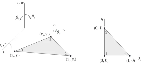
Figure 1: DKT element in the global and nondimensional coordinates.
2.1 Bending Stiffness Matrix
After enforcement of the Kirchhoff constraints at selected points of the DKT element shown in Fig-ure 1, Batoz et al. (1980) demonstrate that the normal rotations are effectively approximated by
(1)
with the nodal values of , and collected in
. (2)
The shape functions identified by
(3)
Have
(4)
given in terms of the nondimensional coordinates
(0, 0)
(1, 0)
(0, 1)
x
h
1 2
3
z, w
b
xb
yx
y
q
xq
y1
(x ,y )
1 12
(x ,y )
2 2 3. (5)
The triangle has area and vertices with global coordinates , . The parameters
(6)
are defined as functions of
(7)
with , , for the triangle sides , , , respectively. Making use of (1), the bending strain energy
(8)
reads
(9)
where are the plate bending rigidities. The element bending stiffness matrix is exactly ob-tained by Batoz et al. (1980) using three-point Gauss quadrature and subsequently stated by Batoz (1982) in explicit form in local coordinates as
, (10)
where
sym. sym. . (11)
The matrix is given in Table I of Batoz (1982).
2.2 Geometric Stiffness Matrix
If the plate is assumed to deform as a membrane prior to buckling with in-plane force distribution , and , the change in membrane strain energy due to buckling reads (Reddy, 2004)
. (12)
The Kirchhoff constraint is now invoked through the plate so that the rotations and can be related to the transverse displacement derivatives by means of
Under this assumption, expression (12) is replaced by
. (14)
Substitution of (1) into (14) yields
(15)
where
(16)
is the consistent geometric stiffness matrix and
. (17)
In order to develop an analytical expression for (16) in closed form, the crucial step is the de-composition of into the product
(18)
where
.
(19)
Independent of coordinates, is given by
.
(20)
In view of (18),
where
. (22)
If is constant over the element,
(23)
with
8
8 8
sym.
. (24)
Note that refers to the global system and has been exactly obtained in closed form. The widely used inconsistent geometric stiffness matrix (Doyle, 2001)
̅ , (25)
in which
, (26)
will be also employed in the buckling analysis for comparison purposes. The matrix is established by adopting the linear displacement field
(27)
in order to compute the derivatives / and / required in (12).
The discrete linearized buckling problem, given by Π , reduces to the linear eigenvalue problem
λ . (28)
Matrix is constructed by assembly of element matrices , whereas is constructed by assembly of element matrices (or ̅ if the inconsistent geometric stiffness matrix is adopted). Vector collects the nodal displacements measured from the buckling point and λ is a constant by which the applied load must be multiplied to cause buckling.
3 NUMERICAL TESTS
compres-sion ( ), biaxial compression and tension ( ), shear ( ). The adopted materials are defined as being
isotropic
orthotropic.
(29)
The boundary conditions will be denoted by SSSS (all edges are simply supported), SSCC (edges are simply supported at , and clamped at , ) and CCCC (all edges are clamped). Assuming the in-plane deformation to be unconstrained prior to buckling, has components
, and .
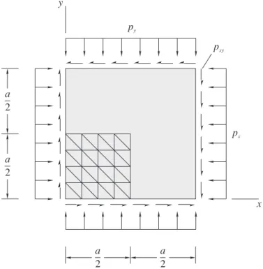
Due to symmetry, only one quarter of the plates is defined as the solution domain for uniaxial compression, biaxial compression, biaxial compression and tension. For shear loading, however, the buckled shape does not exhibit any symmetry and thus the whole plate has to be discretized. A typical mesh in a quarter plate is depicted in Figure 2.
Figure 2: Square plate subjected to uniform in-plane loads , , and mesh in a quarter plate.
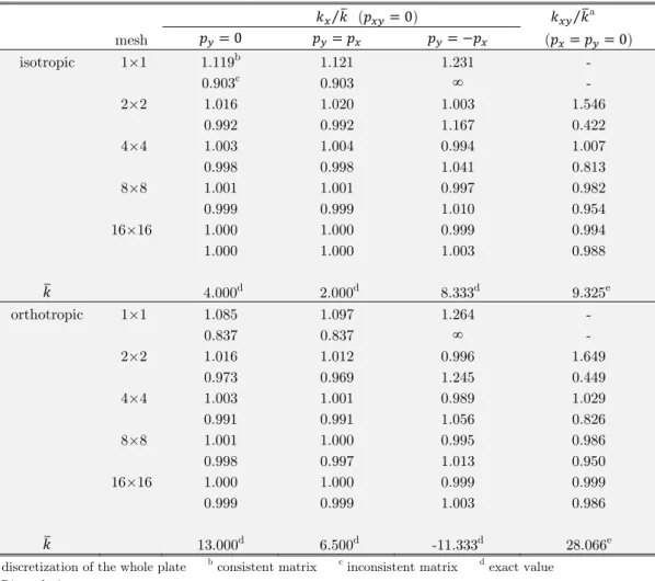
Tables 1-3 summarize the results for the nondimensional buckling loads
, (30)
px
a 2
a 2 a
2 a 2
x y
py
which are obtained for different meshes ( is the number of elements along the plate half side
/ or the plate side , depending on whether the symmetry is adopted or not). Departing from a very coarse mesh , successive meshes are generated by splitting all elements in the current mesh into four smaller ones. For comparison purposes, either exact or approximate reference values of (30) based on Kirchhoff plate theory are provided. While exact values stem from Navier or Lévy solutions (Reddy, 2004), approximate values are accurate results obtained from Ritz solutions em-ploying hierarchic set of functions built from modified Legendre polynomials (Bardell, 1991). No results are tabled for shear loading with mesh because the introduction of the boundary condi-tions after discretization of the whole plate does not leave any degree of freedom available. Moreo-ver, mesh in a quarter may lead to singular geometric stiffness matrices and, consequently, to infinite buckling loads. Both consistent and inconsistent formulations always provide convergence toward exact results with mesh refinement.
⁄ ( ) ⁄ a
mesh ( )
isotropic 1×1 1.119b 1.121 1.231 -
0.903c 0.903 ∞ -
2×2 1.016 1.020 1.003 1.546
0.992 0.992 1.167 0.422
4×4 1.003 1.004 0.994 1.007
0.998 0.998 1.041 0.813
8×8 1.001 1.001 0.997 0.982
0.999 0.999 1.010 0.954
16×16 1.000 1.000 0.999 0.994
1.000 1.000 1.003 0.988
4.000d 2.000d 8.333d 9.325e
orthotropic 1×1 1.085 1.097 1.264 -
0.837 0.837 ∞ -
2×2 1.016 1.012 0.996 1.649
0.973 0.969 1.245 0.449
4×4 1.003 1.001 0.989 1.029
0.991 0.991 1.056 0.826
8×8 1.001 1.000 0.995 0.986
0.998 0.997 1.013 0.950
16×16 1.000 1.000 0.999 0.999
0.999 0.999 1.003 0.986
13.000d 6.500d -11.333d 28.066e
a discretization of the whole plate b consistent matrix c inconsistent matrix d exact value
e Ritz solution
Table 1: Nondimensional buckling load for SSSS square plates: ⁄ ,
⁄ ( ) ⁄ a
mesh ( )
isotropic 1×1 1.092b 1.140 0.951 -
∞c 0.743 ∞ -
2×2 1.004 1.055 0.913 1.385
1.054 1.032 1.071 0.487
4×4 0.995 1.014 0.958 0.966
1.014 1.013 1.010 0.854
8×8 0.998 1.003 0.988 0.976
1.003 1.003 1.001 0.964
16×16 1.000 1.001 0.997 0.993
1.001 1.001 1.000 0.991
7.691d 3.830d 10.788d 12.565e
orthotropic 1×1 1.338 1.416 1.072 -
0.739 0.846 ∞ -
2×2 1.182 1.104 1.395 1.858
1.089 1.077 2.120 0.497
4×4 1.038 1.020 1.044 1.114
1.020 1.023 1.179 0.864
8×8 1.008 1.004 1.008 1.016
1.004 1.004 1.039 0.958
16×16 1.002 1.001 1.002 1.000
1.001 1.001 1.009 0.988
17.604d 7.693d 15.169d 29.567e
a discretization of the whole plate b consistent matrix c inconsistent matrix d exact value e Ritz solution
Table 2: Nondimensional buckling load for SSCC square plates: ⁄ ,
⁄ and is the reference value.
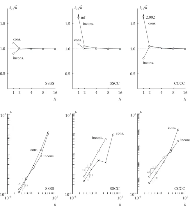
The graphical form of the isotropic plate results are shown in Figures 3-6, where more refined meshes ( and ) are included in the log-log plots of Figures 5 and 6 to ensure that the results obtained with the consistent formulation for biaxial compression/tension and shear loads have also achieved the asymptotic range. Defining / (or / if symmetry is not adopt-ed) as a measure of the element size, and / for or / for
as a measure of the error, the figures also show plotted against on a log-log scale whose slope of the curves is proportional to the rate of convergence.
quadrat-ic rate of convergence, except for SSSS plates under biaxial compression/tension for whquadrat-ich the rate becomes nearly quartic. Although both formulations always provide convergence toward exact re-sults, the buckling load predictions with the consistent formulation are generally better, with higher convergence rate, for coarse meshes and complex modes (plate subjected to shear loading).
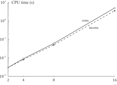
The consistent formulation may be a little more time consuming because expression (21) in-volves more arithmetic operations than (25). In order to confirm our expectation, Figure 7 plots the CPU time to solve CCCC isotropic plates under shear loading. All the calculations were performed in a 3 GH Pentium personal computer with 4 GB of RAM, running a 64-bit Windows 7. It has been observed that the time is practically independent of the loading type and that the change of the boundary conditions from CCCC to SSCC or SSSS has little effect on the time change for the ex-amples considered. Both formulations approximately allows computing the solution in a logarithm of time proportional to .
⁄ ( ) ⁄ a
mesh ( )
isotropic 1×1 2.002b 1.920 1.087 -
0.809c 0.768 ∞ -
2×2 1.055 1.099 1.096 1.326
1.043 1.062 1.340 0.583
4×4 1.010 1.019 0.989 1.000
1.018 1.019 1.080 0.861
8×8 1.002 1.004 0.994 0.980
1.005 1.005 1.018 0.962
16×16 1.000 1.001 0.998 0.993
1.001 1.001 1.004 0.989
10.074d 5.304d 14.966d 14.642d
orthotropic 1×1 1.622 0.975 ∞ -
0.649 ∞ ∞ -
2×2 1.094 1.247 1.160 1.257
0.992 1.433 1.237 0.768
4×4 1.016 1.016 1.015 1.137
1.002 1.060 1.191 0.909
8×8 1.004 1.002 0.999 1.014
1.000 1.012 1.042 0.947
16×16 1.001 1.000 0.999 0.994
1.000 1.003 1.010 0.983
46.289d 16.681d 24.066d 46.726d
a discretization of the whole plate b consistent matrix c inconsistent matrix d Ritz solution
Table 3: Nondimensional buckling load for CCCC square plates: ⁄ ,
Figure 3: Uniaxial buckling load ( , ) for isotropic plates: nondimensional load / versus and error versus element size .
2 4 8 16
0.5 1.0 1.5 0.5 1.0 1.5 N 0.5 1.0 1.5 N k /kx
CCCC
k /kx k /kx
2 4 8 16 2 4 8 16
1 1 1
incons. SSSS cons. incons. 2.002 SSCC cons. inf incons. cons. N 10-2 10-4 h 10-4 10-2 h 10-2 10-4 h 101 SSCC CCCC
e e e
100
100 100
100 100
Figure 4: Biaxial compression buckling load ( , ) for isotropic plates: nondimensional load / versus and error versus element size .
2 4 8 16
0.5 1.0 1.5
N 0.5 1.0 1.5
N 0.5 1.0 1.5
N
k /kx k /kx k /kx
2 4 8 16 2 4 8 16
1 1 1
incons. cons.
incons. cons.
incons.
1.920 cons.
e e e
10-2 10-4
h
10-4 10-2
h
10-2 10-4
h 100
100
100 100
100 100
CCCC
SSSS SSCC
SSCC CCCC
SSSS 1.9
1 2.0
1
2.1 1
2.1 1 cons.
incons.
cons. incons.
cons.
Figure 5: Biaxial compression/tension buckling load ( , ) for isotropic plates: nondimensional load / versus and error versus element size .
2 4 8 16
0.5 1.0 1.5 N 0.5 1.0 1.5 N 0.5 1.0 1.5 N
k /kx k /kx k /kx
2 4 8 16 2 4 8 16
1 1 1
cons. incons. cons. incons. cons. incons. inf inf inf e e h 100
10-6 10-4
Figure 6: Shear buckling load ( , ) for isotropic plates: nondimensional load / versus and error versus element size .
2 4 8 16
0.5 1.0 1.5
N cons.
incons.
0.5 1.0 1.5
N cons.
incons. 0.5
1.0 1.5
N cons.
incons.
k /kxy k /kxy k /kxy
2 4 8 16 2 4 8 16
e e e
10-4 10-4
100
100 100
10-4 10-3
h
10-3
h
10-3
h
100 100 100
SSCC CCCC
SSSS
CCCC
SSSS SSCC
cons.
incons. cons.
incons. incons. cons.
1.8 1 1.9
1
2.0 1
Figure 7: CPU time consumption in seconds versus to solve CCCC isotropic plates under shear loading.
4 CONCLUSIONS
To the simple and effective DKT element is offered an explicit form of its consistent geometric stiff-ness matrix in global coordinates. This proposed form avoids the expensive exact integration by seven-point Gauss quadrature and transformations from local to global coordinates. Based on the examples considered, the following conclusions can be drawn with respect to the performances of the consistent and inconsistent formulations:
Both formulations always provide convergence toward exact results with mesh refinement.
A solution obtained by the consistent formulation is a little more time consuming, and both formulations approximately allows computing the solution in a logarithm of CPU time pro-portional to .
An approximately quadratic rate of convergence is usually observed for the consistent formu-lation in the asymptotic range, whereas the inconsistent formuformu-lation has such a rate through all the mesh refinement.
For complex buckling modes, as it is the case of plates under shear loading, the consistent formulation gives more precise results for coarse meshes.
References
ABAQUS Theory Manual, Version 6.12, ABAQUS, Inc., Dassault Systèmes Simulia Corp., Providence, USA, 2012. Bardell, N.S. (1991). Free vibration analysis of a flat plate using the hierarchical finite element method. Journal of Sound and Vibration 151(2): 263-289.
Bathe, K.J., Ho, L.W. (1981). A simple and effective element for analysis of general shell structures. Computers and Structures 13(5-6): 673-681.
cons.
incons.
N
2 4 8 16
CPU time (s)
10-3
Batoz, J.L. (1982). An explicit formulation for an efficient triangular plate-bending element. International Journal for Numerical Methods in Engineering 18 (7): 1077-1089.
Batoz, J.L., Bathe, K.J., Ho, L.W. (1980). A study of three-node triangular plate bending elements. International Journal for Numerical Methods in Engineering 15(12): 1171-1812.
Belytschko, T., Lin, J.L., Tsay, C.S. (1984). Explicit algorithms for the nonlinear dynamics of shells. Computer Methods in Applied Mechanics and Engineering 42(2): 225-251.
Bernadou, M. (1996). Finite Element Methods for Thin Shell Problems. John Wiley, New York. Brush, D.O., Almroth, B.O. (1975). Buckling of Bars, Plates, and Shells. McGraw-Hill, New York.
Cook, R.D. (1993). Further development of a three-node triangular shell element. International Journal for Numeri-cal Methods in Engineering 36 (8): 1413-1425.
Cook, R.D., Malkus, D.S., Plesha, M.E., Witt R.J. (2002). Concepts and Applications of Finite Element Analysis. John Wiley, New York.
Doyle, J.F. (2001). Nonlinear Analysis of Thin-Walled Structures: Statics, Dynamics, and Stability. Springer, New York.
Garnet, H., Pifko, A.B. (1983). An efficient triangular plate bending finite element for crash simulation. Computers and Structures 16(1-4): 371-379.
Jeyachandrabose, C., Kirkhope, J., Babu, C. R. (1985). An alternative explicit formulation for the DKT plate-bending element. International Journal for Numerical Methods in Engineering 21(7): 1289-1293.
Khosravi, P., Ganesan, R., Sedaghati, R. (2007). Corotational non-linear analysis of thin plates and shells using a new shell element. International Journal for Numerical Methods in Engineering 69(4): 859-885.
Kikuchi, F. (1975). On a finite element scheme based on the discrete Kirchhoff assumption. Numerische Mathematik 24(3): 211-231.
Mateus, H.C., Soares, C.M.M., Soares, C.A.M. (1997). Buckling sensitivity analysis and optimal design of thin lami-nated structures. Computers and Structures 64(1-4): 461-472.
Reddy, J.N. (2004). Mechanics of Laminated Composite Plates and Shells: Theory and Analysis. CRC Press, Boca Raton.
Strickling, J.A., Haisler, W.E., Tisdale, P.R., Gunderson, R. (1969). A rapidly converging triangular plate element. AIAA Journal 7(1): 180-181.
Wu, S., Li, G., Belytschko, T. (2005). A DKT shell element for dynamic large deformation analysis. Communications in Numerical Methods in Engineering 21(11): 651-674.