Abstract
The simulation of cryogenic machining process because of using a three-dimensional model and high process duration time in the finite element method, have been studied rarely. In this study, to overcome this limitation, a 2.5D finite element model using the commercial finite element software ABAQUS has been developed for the cryo-genic machining process and by considering more realistic assump-tions, the chip formation procedure investigated. In the proposed method, the liquid nitrogen has been used as a coolant. At the mod-eling of friction during the interaction of tools – chip, the Coulomb law has been used. In order to simulate the behavior of plasticity and failure criterion, Johnson-Cook model was used, and unlike previous investigations, thermal and mechanical properties of materials as a function of temperature were applied to the software. After examin-ing accuracy of the model with present experimental data, the effect of parameters such as rake angle and the cutting speed as well as dry machining of aluminum alloy by the use of coupled dynamic temper-ature solution has been studied. Results indicated that at the cutting velocity of 10 m/s, cryogenic cooling has caused into decreasing 60 percent of tools temperature in comparison with the dry cooling. Furthermore, a chip which has been made by cryogenic machining were connected and without fracture in contrast to dry machining.
Keywords
Cryogenic Machining, finite element method (FEM), liquid nitro-gen, coupled dynamic- thermal analysis.
Investigation of High-Speed Cryogenic Machining
Based on Finite Element Approach
1 INTRODUCTION
In machining operations, mechanical energy, as a result of plastic deformation and friction is convert-ing into thermal energy. This sudden increase in temperature results in a reduction of tool life, low quality of machined surfaces and additional charges. The cutting tools are an important factor in enhancing the efficiency of machining operations. Therefore, many researchers’ have been done to
Pooyan Vahidi Pashaki a Milad Pouya b
a School of Mechanical Engineering,
Islamic Azad University- science and research branch, Tehran, Iran, E-mail: [email protected]
b School of Mechanical Engineering,
International Pardis, University of Guilan, Rasht, Iran, Email: [email protected]
http://dx.doi.org/10.1590/1679-78253493
increase the life of cutting tools to meet industry requirements (Atlati et al. (2015), Buchkremer et al. (2015), Ducobu et al. (2015), Fu et al. (2016), Gao et al. (2015), Zhu et al. (2016)). Since experi-mental studies in the field of machining operation are costly, time-consuming and are limited so that, today researchers are using finite element methods as an efficient tool for their studies.
Most of the simulations aimed at obtaining the amount of residual stress and strain (Tounsi and El-Wardany (2015), Yang et al. (2016), Mahmoodi-k et al. (2014)), temperature distribution (Healy et al. (2015), Pittalà and Monno (2011)), and deformation of chip and predict the forces of machining (Khoshdarregi and Altintas (2013), Molnár et al. (2015), Wu et al. (2015). Yildiz et al. (2008), have been examined the studies in the field of cryogenic cooling method in machining processes and con-cluded that this approach can be used for various metals, including hard and soft metals, non-ferrous metals and non-metallic materials and composites. Zhan et al. (2011) simulated the formation of the chip and also examined the effect of cutting speed, the coefficient of friction and the rake angle by considering shear stress at the border area of chip and tool. Their results indicated that the cutting speed or higher feed rate is likely at the disruption of the chip. Cotterell and Byrne (2008), have studied the dynamics of chip formation in orthogonal machining of titanium alloy and demonstrated that disruption frequency of chip increased linearly with increasing cutting velocity. Pusavec (2012), has compared the machining of the tungsten of cryogenic method with the method of plastic injection and has considered its impact on some cutting parameters, cutting tool and the surface porosity. Then by using genetic algorithms has predicted values for the most optimal machining parameters. He also revealed that this method could be replaced by plastic injection method which has many environmen-tal problems and physical hazards for the operator and will increase tools life and improve the per-formance of tools. Chen et al. (2004) have simulated the chip formation, cutting forces, stress, and strain and temperature distribution in orthogonal machining process by using a 2D finite element model. The Comparison of the obtained results in the case of cutting forces with the experimental results was satisfactory.
CNC machine tools can effect on machining process parameter, Pashaki and Pouya (2016) have developed volumetric error compensation in five-axis CNC machine tools to increase the accuracy of machined workpiece.
Examination of the further studies in recent years indicate that the cryogenic machining process diagonally so far has not been considered by researchers and parametric study on the effective pa-rameters in this area is needed. Therefore, in this study, more realistic model of the simulation process is provided by the use of 2.5D finite element cryogenic machining based on Arbitrary Lagrangian-Eulerian (ALE) simulations. Johnson-Cook Plasticity Model for material plasticity model and failure criterion of Johnson-Cook is used to create the chip. Unlike conducted researches, in order to consider more realistic model, the finite element model has been provided more accurately and by taking into account the effect of temperature on mechanical properties of materials and using coupled dynamic-temperature analyzes the cryogenic process has been simulated. After ensuring the accuracy of the results, the effect of present parameters on the cryogenic machining process and cutting forces as well as stress distribution, temperature and plastic deformation and residual stress are discussed.
2 THE NUMERICAL MODEL AND CONSTITUTIVE RELATIONS
In the current research, a 2.5D finite element model by using the ABAQUS has been created to simulate the cryogenic machining. The analysis is performed by Lagrangian formulation and as an explicit dynamic. Since the machining is being performed diagonally, the tool possesses the angle of inclination. Tool angles have been represented in Fig. 1-a. Work piece and tools were defined both as deformable.
(a) (b)
2.1 Cryogenic Cooling
In the present study cryogenic as spray cooling is examined. In this case, the cutting area particularly the contact surface of tool and chip with liquid nitrogen dispersion is being cooled by nozzles. At the finite element model, the cryogenic cooling impact on the workpiece is applied using convection heat transfer as follows:
(
)
c cryo room
q
h
T
T
(1)Where in, hcryo is the heat transfer coefficient, T is the surface temperature, and Troom is ambient
temperature. Considering the aspects of heat transfer model, the temperature of the low surface and left side of workpiece same as an upper surface and right side of the cutting tools is considered equal to the ambient temperature Troom which is25 Co . The upper surface and right side of the workpiece
same as a lower surface and left the surface of removal material tools are under the influence of mandatory heat transfer. In Figure 1-a thermal boundary conditions have been represented. In the forced heat transfer surfaces by cryogenic cooling, the Troom temperature is to be considered 196 Co
due to the use of liquid nitrogen. Also, to consider more realistic assumptions of cryogenic cooling, more details of convective heat transfer is desired. For this purpose, according to the study Miranda (2013) heat transfer coefficient was considered as follows:
0.65 0.67 0.33 0.33
0.35 0.33 0.32
0.2
f f p fcryo
f
V
k
c
h
e
g
v
(2)where e is the equivalent length, g gravity acceleration and other parameters are as follows: Vf speed
(ms-1),
f
k thermal conductivity (W m C-1 o ), f density (
-3
kg m ),vf dynamic viscosity (Pas) and
c
pspecific heat capacity (J kg C-1 o ).
According to equation (2) and taking into account the physical and thermal properties of liquid nitrogen, heat transfer coefficient is a function of temperature which is achieved as follows:
6 3 2
8 10 0.0149 44.396 10162
cryo
h T T T (3)
2.2 Plastic Criterion of Johnson-Cook
The material of tool and workpiece are considered steel aluminum respectively. To modeling of the plastic behavior of materials, Johnson-Cook Plasticity model is used. According to this model, the plastic behavior of materials is expressed as the below equation:
room
0 melt room
( ) 1 ln 1
m
n T T
A B C
T T (4)
2009). When Johnson-Cook model of dependent on the strain rate is being used the values of 0 and C should be determined.
2.3 Exhaustion Criterion of Johnson-Cook
For modeling of the chip formation, failure criterion of Johnson-Cook model is being used. Based on this test, deterioration parameter D in the equation (5) is defined which as should not exceed from number 1.
pl
pl f
D
(5-a)room
1 2 3 4 5
0 melt room
exp(
) 1
ln
pl1
pl f
p
T
T
d
d
d
d
d
q
T
T
(5-b)In the recent equation, pl f
is failure strain p is pressure and q is effective stress of Von-Mises. , ( 1,2,...,5)i
d i are material constants, which values are represented in Table 2 for steel tool and aluminum workpieces.
2.4 Model of Coulomb Friction
The central concept of Coulomb friction pattern is the allowed maximum tangential friction (shear) on the length of the contact surface up to the contact pressure between the contact bodies. In this paper, the resistance model between the shared surface of the tool and the workpiece is defined by using Coulomb criterion. In this case, the frictional stress is considered as proportional to the normal tension
n. Coulomb friction model is defined as follows:n
(6)
In which is considered as the friction coefficient.
2.5 Meshing and Arbitrary Lagrangian-Eulerian (ALE) Simulations
In the chip formation process due to the high range of deformation, there is a lot of error associated with simple meshing process. In this study, the Adaptive Meshing method is used. The full name of the method is used; the Arbitrary Lagrangian-Eulerian method is conventional that it is more com-monly referred to as ALE. According to the dynamic-temperature coupling analysis for meshing, 3D elements C3D8T that is an eight-node thermal coupled element is used. The surface of material removal with the depth of 1 mm with smaller features has meshed and other parts with larger ele-ments. Boundary conditions and used meshing method is represented in Figure 1.
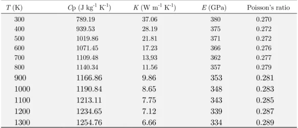
2.6 Mechanical and Thermal Properties of Used Materials
temperature of the workpiece during the machining process and tools increase extremely high, there-fore, unlike the previous researches, mechanical and thermal properties of materials are considered as a function of temperature. The used thermal and mechanical properties for Al and AISI 316L at different temperatures are provided in Tables 3 and 4 respectively.
0
Troom
(oC) Tmelt
(oC) m C n B (MPa) A (MPa) 1 20 926 0 0.002 0.426 113.8 324.1 Al (Umbrello et al. 2007)
1 20 1460 0.517 0.01 0.613 1161 305 AISI 316L (Umbrello et al. 2007)
Table 1: The values of variables of equation of Johnson-Cook Plasticity Model.
d5 d4 d3 d2 d1 0 0 -0.47 1.45 -0.77 Al 0 0 2.68 4.38 0.25 AISI 316L
Table 2: The values the constant equation of Johnson-Cook failure model.
Poisson’s ratio E (GPa)
K (W m-1 K-1) Cp (J kg-1 K-1)
T (K)
0.270 380 37.06 789.19 300 0.272 375 28.19 939.53 400 0.272 371 21.81 1019.86 500 0.276 366 17.23 1071.45 600 0.277 362 13,93 1109.48 700 0.279 357 11.56 1140.34 800 0.281 353 9.86 1166.86 900 0.283 348 8.65 1190.84 1000 0.285 343 7.75 1213.11 1100 0.287 339 7.12 1234.65 1200 0.289 334 6.66 1254.76 1300
Table 3: The thermal and mechanical properties of the used aluminum in the simulation (Yilbas et al. 2016).
Density (kg m-3): ( ) 7921 0.614T T0.0002T2 AISI 316L
steel32 Thermal conductivity (W m
-1 K-1): k T( ) 14.307 0.0181 T 6 106T2
Specific heat (J kg-1 K): ( ) 440.79 0.5807 0.001 2 7 107 3 p
c T T T T
Table 4: The mechanical and thermal properties of used AISI 316L in simulation.
3 RESULTS AND DISCUSSION
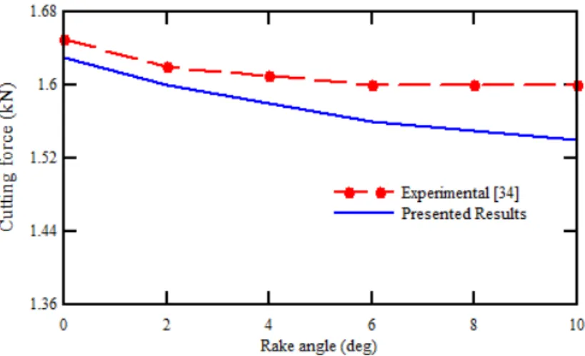
from simulation and experimental analysis are represented. As can be seen, the simulation outcomes have an acceptable agreement with experimental results presented in Ref. (Günay, 2005) and the maximum predicted error of the model is less than 8 percent. Although there are differences between experimental and numerical results, but the error rate due to the uncertainty of coefficients related to the behavior of the material, is acceptable.
Figure 2: Compares the obtained mechanical cutting force by the use of the presented model and the experimental results of Ref. (Günay, 2005).
Afterward, by assuring the reliability of the conducted modeling, to evaluate the changes of any of the practical parameters, the length of the chip has been measured in ABAQUS software and according to this measure, the results were compared.
3.1 The Effect of Cryogenic Cooling
At first, for more considerations over the effects of the cryogenic process on the machining operations. In figure 3 the temperature distribution of the workpiece and cutting tool for rake angle of 32o and cutting edge inclination angle of 10o in machining with cutting speed of 10 m/s for both cooling, dry and cryogenic cooling is represented. Also in these figures, the effect of consideration of thermal stress on the geometrical shape of the chip and residual stress have been represented. By comparing Fig. 3-a 3-and 3-b it c3-an be found th3-at the dyn3-amic resolution without considering the therm3-al tensions, first the length of the chip is lower and second less residual strain has been received. According to the results of the conducted analysis of machining, the coupled dynamic analysis of displacement-thermal should be used.
(a) (b) (c)
Figure 3: Compares the residual strain distribution and chip shapes (a) dynamic analysis, (b) thermal-dynamic coupled analysis in dry machining and (c) thermal-dynamic coupled analysis in cryogenic machining.
(a) (b)
Figure 4: The temperature (K) distribution of machining of work piece in two modes (a) dry machining and (b) cryogenic machining.
(a) (b)
Figure 5: The distribution of tools temperature (K) in two modes (a) dry machining and (b) cryogenic machining.
that compressive and tensile residual stress of cryogenic machining in this case approximately is 20.12 and 24.39 percent lower than dry machining that the reason of it can be the low temperature of cryogenic machining and as a result, causes in low thermal stress. It is indicated that in both cases, the maximum compressive stress is at the contact zone of the tool and the workpiece and the area of the second shear due to high heat transfer and more thermal gradient, these stress are tensile.
(a) (b)
Figure 6: The distribution of residual stress (Pa) in two modes (a) dry machining and (b) cryogenic machining.
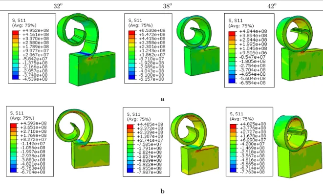
3.2 The Effect of Rake Angle
42o 38o
32o
a
b
Figure 7: The distribution of residual stress (Pa) in (a) dry machining and
(b) cryogenic machining in different rake angles in cutting speed of 30 m/s.
42o
38o
32o
a
b
Figure 8: The temperature (K) distribution in (a) dry machining and
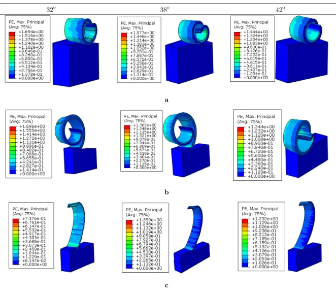
3.3 The Cutting Speed Effect
Three various speeds of 10, 30 and 60 m/s have been studied to investigate the impact of cutting speed on chip features. The depth of cut and angle of inclination of tools is considered to be fixed and respectively equal to 0.5 mm and 10 degrees. In figure 9 the impact of cutting speed on the formation of the chip is represented in cryogenic machining process and different rake angles. The results rep-resent that at low cutting speeds, the chip are conical and by speeding up the chip are more open and lose the conical shape. It can be said the most conical formation of the chip and disconnection of the newly formed chip with previous chip causes in increasing the length of the chip and reduces the break in them. According to figures also it is observed that at speeds of 10 and 30 m/s the increasing of the rake angle causes the reduction of residual plastic strains in the chip, but at higher speeds (60 m/s) the greatest strain occurs in the chip for the angle of 38 degrees.
42o 38o
32o
a
b
c
4 CONCLUSION
In the machining process using cooling increases tool life, dimensional accuracy, and makes to better roughness which cause reduction of temperature and energy consumption and leads to improved productivity. Therefore, in this study, the finite element model is considered for oblique cutting with cryogenic cooling. To simulate material removal process and separation of chip, the plastics criterion materials as well as material damage, the Johnson-Cook model was used, and mechanical and thermal behavior of materials were applied as a function of temperature. After analyzing the simulated model by using coupled thermal-dynamic solutions model, the impact of parameters such as the speed of material removal, rake angle on residual stress and shape of the chip and also comparison of the results with dry and cryogenic machining have been considered. The results represent that applying thermal and mechanical loads in the workpiece during the machining process, in fluencies the residual stress and tensile stress distribution in the cryogenic process is more than dry machining and this fact on at residual stress on compression is vice versa. At the cutting speed of 10 m/s in cryogenic ma-chining respectively causes in the reduction of 71.34 and 76.64 percent of temperature of the chip and tool in comparison to dry machining. It is observed that temperature of the chip in cryogenic ma-chining is 50% reduces to dry mama-chining and rake angle of 38 degrees shows more the generated temperature. The results also represent that the chip formed in cryogenic machining to be connected and without a fracture, unlike the dry machining. However, at speeds of less than 30 m/s shape of the chip are conical, and at high speeds has been created strips. Also, as the rake angle increases the conical shape of chip reduces.
References
Atlati, S., Haddag, B., Nouari, M and Moufki A., (2015). Effect of the local friction and contact nature on the Built-Up Edge formation process in machining ductile metals. Tribology International 90: 217-27.
Bajpai, V., Lee, I and Park, H.W., (2015). FE Simulation of Cryogenic Assisted Machining of Ti Alloy (Ti6AI4V). ASME 2015 International Manufacturing Science and Engineering Conference. American Society of Mechanical Engi-neers V001T02A28-VT02A28.
Biermann, D., Abrahams, H., Metzger, M., (2015). Experimental investigation of tool wear and chip formation in cryogenic machining of titanium alloys. Advances in Manufacturing 3: 2-9.
Buchkremer, S., Klocke, F and Lung, D., (2015). Finite-element-analysis of the relationship between chip geometry and stress triaxiality distribution in the chip breakage location of metal cutting operations. Simulation Modelling Practice and Theory 55: 10-26.
Chen, S.J., Pang, Q., Cheng, K., (2004). Finite element simulation of the orthogonal metal cutting process. Materials Science Forum. Trans Tech Publ 582-586.
Cotterell, M., Byrne, G., (2008). Dynamics of chip formation during orthogonal cutting of titanium alloy Ti–6Al–4V. CIRP Annals-Manufacturing Technology 57: 93-96.
Davim, J., Maranhão, C., (2009). A study of plastic strain and plastic strain rate in machining of steel AISI 1045 using FEM analysis. Materials & Design30: 160-165.
Dhananchezian, M., Kumar, M.P., (2011). Cryogenic turning of the Ti–6Al–4V alloy with modified cutting tool inserts. Cryogenics 51: 34-40.
Ducobu, F., Rivière-Lorphèvre, E. and Filippi, E., (2015).Experimental contribution to the study of the Ti6Al4V chip formation in orthogonal cutting on a milling machine. International Journal of Material Forming 8: 455-468.
Fu, X., Chen, G., Yang, Q., Sun, Z. and Zhou, W., (2016). The influence of hydrogen on chip formation in cutting Ti-6Al-4V alloys. The International Journal of Advanced Manufacturing Technology 1-5.
Gao, Y., Wang, G., Bermingham, M.J. and Dargusch, M.S., (2015). Cutting force, chip formation, and tool wear during the laser-assisted machining a near-alpha titanium alloy BTi-6431S. The International Journal of Advanced Manufac-turing Technology 79: 1949-1960.
Giasin, K., Ayvar-Soberanis, S. and Hodzic, A., (2016). Evaluation of cryogenic cooling and minimum quantity lubri-cation effects on machining GLARE laminates using design of experiments. Journal of Cleaner Production 135: 533-548.
Günay, M., (2015). Experimental investigation of the effect of cutting tool rake angle on main cutting force. Journal of materials processing technology 166(1): 44-49.
Gupta, M.K., Singh, G. and Sood, P.K., (2015). Experimental investigation of machining AISI 1040 medium carbon steel under cryogenic machining: A comparison with dry machining. Journal of The Institution of Engineers (India): Series C 96: 373-379.
Healy, C., Koch, S., Siemers, C., Mukherji, D. and Ackland, G.J., (2015). Shear melting and high temperature embrit-tlement: theory and application to machining titanium. Physical review letters 144: 165-176.
Hocheng, H., (2011). Machining technology for composite materials: principles and practice. Elsevier.
Jun, S-C., (2005). Lubrication effect of liquid nitrogen in cryogenic machining friction on the tool-chip interface. Journal of mechanical science and technology 19: 936-946.
Khoshdarregi, M.R. and Altintas, Y., (2015). Generalized modeling ofchip geometry and cutting forces in multi-point thread turning. International Journal of Machine Tools and Manufacture 98: 21-32.
Mahmoodi-k, M., Davoodabadi, I., Višnjić, V., Afkar, A., (2014). Stress and dynamic analysis of optimized trailer chassis, Tehnički vjesnik, 21: 599-608
Miranda, R., (2013). Metalworking fluids (MWFs) for cutting and grinding–Fundamentals and recent advances. Inter-national Journal of Environmental Studies 70: 337-341.
Molnár, T.G., Insperger, T., Hogan, S.J. and Stépán, G., (2015). Investigating multiscale phenomena in machining: the effect of cutting-force distribution along the tool’s rake face on process stability. ASME 2015 International Design Engineering Technical Conferences and Computers and Information in Engineering Conference. American Society of Mechanical Engineers 63-83.
Pashaki, P. and Pouya, M., (2016). Volumetric error compensation in five-axis cnc machining center through kinemat-ics modeling of geometric error, advances in science and technology research journal 10: 207-217.
Pittalà, G.M. and Monno, M., (2011). A new approach to the prediction of temperature of the workpiece of face milling operations of Ti-6Al-4V. Applied Thermal Engineering 31: 173-180.
Pusavec, F., (2012). Porous tungsten machining under cryogenic conditions. International Journal of Refractory Metals and Hard Materials 35: 84-89.
Rana, K., Rinaldi, S., (2016). Imbrogno S, et al. 2D FE Prediction of Surface Alteration of Inconel 718 under Machining Condition. Procedia CIRP 45: 227-230.
Schoop, J., Ambrosy, F., Zanger, F., Schulze, V., Balk, T. and Jawahir, I., (2016). Cryogenic machining of porous tungsten for enhanced surface integrity. Journal of Materials Processing Technology 229: 614-621.
Tounsi, N. and El-Wardany, T., (2015). Finite element analysis of chip formation and residual stresses induced by sequential cutting in side milling with microns to sub-micron uncut chip thickness and finite cutting edge radius. Advances in Manufacturing 3: 309-322.
Umbrello, D., M’saoubi, R. and Outeiro, J., (2007). The influence of Johnson–Cook material constants on finite element simulation of machining of AISI 316L steel. International Journal of Machine Tools and Manufacture 47: 462-470. Wu, X., Li, L., He, N., Zhao, M. and Zhan, Z., (2015). Investigation on the influence of material microstructure on cutting force and bur formation in the micro cutting of copper. The International Journal of Advanced Manufacturing Technology 79: 321-327.
Yang, D., Liu, Z., Ren, X. and Zhuang, P., (2016). Hybrid modeling with finite element and statistical methods for residual stress prediction in peripheral milling of titanium alloy Ti-6Al-4V. International Journal of Mechanical Sciences 108: 29-38.
Yilbas, B., Akhtar, S. and Karatas, C., (2016). Laser machining of different diameter holes inalumina ceramic: Thermal stress analysis. Machining Science and Technology 20: 349-367.
Yildiz, Y. and Nalbant, M., (2008). A review of cryogenic cooling in machining processes. International Journal of Machine Tools and Manufacture 48: 947-964.
Zhang, Y., Mabrouki, T., Nelias, D. and Gong, Y., (2011). Chip formation in orthogonal cutting considering interface limiting shear stress and damage evolution based on fracture energy approach. Finite Elements in Analysis and De-sign47: 850-863.