*e-mail: [email protected]
High Performance Concrete Applied to Storage
System Buildings at Low Temperatures
Sandra Maria de Lima*, Luiz Vicente Vareda, Jefferson Benedicto Libardi Liborio
Department of Structural Engineering, School of Engineering of São Carlos,
University of São Paulo,
Av. Trabalhador Sãocarlense, 400, Centro, 13566-590, São Carlos - SP, Brazil
Received: January 25, 2007; Revised: April 4, 2008
According to some estimates, world’s population growth is expected about 50% over the next 50 years. Thus, one of the greatest challenges faced by Engineering is to find effective options to food storage and conservation. Some researchers have investigated how to design durable buildings for storing and conserving food. Nowadays, developing concrete with mechanical resistance for room temperatures is a parameter that can be achieved easily. On the other hand, associating it to low temperature of approximately 35 °C negative requires less empiricism, being necessary a suitable dosage method and a careful selection of the material constituents. This ongoing study involves these parameters. The presented concrete was analyzed through non-destructive tests that examines the material properties periodically and verifies its physical integrity. Concrete with and without incorporated air were studied. The results demonstrated that both are resistant to freezing.
Keywords: concrete, high-performance, food conservation
1. Introduction
Employing refrigeration/cooling and freezing processes for food conservation is an essential feature about answering population growth demands. These processes allow suitable storage as well as a world-wide exchange of perishable foodstuffs. In addition, stocks can be controlled during and after harvest periods.
Lots of industrial sectors have used refrigeration/cooling tech-nology during the food transportation to make high quality products available to the domestic and international market. In order to help this kind of business, concrete material was proposed as an alternative for preserving food systems at temperatures up to –35 °C.
For these industries, deterioration on their installations frequently causes considerable damage. However, maintenance itself represents the lowest expense. Actually, the circumstances around it bring the highest costs. One of them is factory downtime, when there is waste of time and workforce. Another one is the embargoes imposed during inspections, when any inadequate cleanliness conditions are detected on the installations.
Developing this concrete involved designing scientifically a mate-rial resistant to severe environment conditions, mainly low tempera-tures and use demands (i.e. equipment carrying, storage, chemical attack). At the same time, this material must be more cost-effective in comparison to other alternative constructions. Some positive features should be cost reduction for concrete producing and a significant durability of the building material.
2. Literature Review
2.1. The effect of low temperatures on concrete
The resulting problem to expose concrete to low temperatures is that being a porous material, concrete is able to store water. As this liquid volume increases during freezing process and the exceeding volume moves through the concrete capillaries, the pressure increases in the walls.
Powers1 and Powers and Helmuth2 performed a series of experi-ments which allowed understanding freezing action in concrete. They reported two phenomena as being the cause of deterioration in this material when it is exposed to low temperatures: 1) the generation of hydraulic pressure and 2) the diffusion of water-gel and capillary water.
When the water contained in the concrete capillaries solidifies, it causes hydraulic pressure. This takes place due to the volume water increase and makes the exceeding amount moving to the capillaries or to the innermost cavities. This migratory movement provokes pressure in the capillary walls, which will become deformed if this pressure surpasses the material resistance. Then, if the migratory flow will not be enough to relieve the pressure, even the capillary filled with ice will crack. This phenomenon is named hydraulic pressure generation.
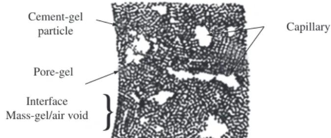
The capillary voids in the concrete can have different sizes (Figure 1). The bigger is the dimension of these voids, the higher is the temperature of freezing water they contain. Moreover, the coexistence of water in different physical states as well as its freezing at different temperatures in the concrete brings the depletion of water from the smallest capillaries into the biggest ones. This happens because the highest levels of energy can be found in the smallest capillaries with the greatest saturation degrees.
This phenomenon is called capillary diffusion and it begins in the mass-gel, where the smallest voids are found in the concrete. Initially, the diffusion of water-gel makes contractions. On a second stage, this depletion to the capillaries or cavities causes an increase in the ice crystals inside of them. Then, when there aren’t enough voids for storing the excess of water, these ice crystals can provoke deformation.
sug-gests incorporating 6 ± 1% of air incorporated into the concrete in order to protect it from freezing. However, these voids should be near the others so that their diameter is, on average, the distance between its walls. Powers1 also demonstrated that if the ratio water/binder is limited at 0.25, completely hydrated cement bulk will not be damaged by low temperatures because of the stored freezing water elimination from the pores of this cement bulk.
2.2. Assessment of damage to concrete by freezing
Tests exposing concrete to low temperatures must not be de-structive because the specimens should be returned to the target temperature environment (i.e. cold chamber) keeping their physical integrity. Determining the natural frequency of the specimens makes this analysis possible.
The natural frequency is the free oscillation rate brought by the application of an outside force, or in other words, the number of times the specimens are moved from the reference point to the displaced point in a period of time.
The test taken to analyze the performance of the specimens from concrete exposed to low temperatures is, therefore, dynamic or related to vibration. The stiffness (elasticity), the capacity of receiving an impact (damping) and the mass from particular specimens are the mechanical parameters that rule a mechanical vibration system. The way these parameters interact defines the mechanical vibration in a certain body.
The natural frequency of any body can be related to its physical integrity, since this is proportional to its stiffness (elasticity). Thus, in this research, the natural frequency will be the parameter used to measure any damage found in the concrete when exposed to low temperatures.
Freezing can cause deformations due to the expansion or contrac-tion of the specimens, depending on the predominant mechanism: generation of hydraulic pressure or diffusion of the water contained in the pore-gel and capillaries, respectively.
The deformations caused by these phenomena were monitored using pairs of mechanical strain gauges fixed on the specimen sur-face and whose readings were checked through a measuring clock (Tensotast), which fits in the pairs of mechanical strain gauges fixed to the surface of the specimens.
3. Experimental Work
3.1. Method
The following entities set the parameters for the experiment: a) International Federation for Structural Concrete (fib)4:
maxi-mum water/binder ratio = 0.45; minimaxi-mum resistance class - C30/37; minimum cement consumption - 340 kg/m3; minimum air content - 4%. These specifications correspond to the rank of environmental damage XF4 - freezing and thawing damaging effects, in a saturated condition and in the presence of thawing agents or sea water.
b) Instructions for Structural Concrete (EHE)5: maximum water/ binder ratio = 0.50; minimum resistance class - C30; minimum cement consumption 325 kg/m3; minimum air content 4.5%. These specifications correspond to the rank of environmental damage F – freezing and thawing action in the presence of salts and/or deicing chemicals.
c) American Concrete Institute (ACI 318-83): maximum water/ binder ratio = 0.45 for features such as kerbs, pipes and hand-rails and 0.50 for other ones. (Mehta and Monteiro)6. The previous parameters determined the water/binder ratio employed. Besides this, since a reduced concrete cost was intended, the approximate water/ binder ratio was about 0.40 and 0.45, being the final value of water/binder and ratio 1: m defined from dosage abacus making.
Portland cement CP II E 32 and silica fume (from iron-silicon or metallic silicon suspender manufacturing) constituted the high performance concrete or HPC. The small and coarse aggregates came from São Carlos/SP region: river sand and crushed basaltic with a maximum size of 19 mm, respectively. Policarboxilic su-perplasticizers (Glenium 51) and air incorporators (IAR) were the additives used.
The Portland cement CP II E 32 was chosen for the HPC subjected to low temperature environments due to the following reasons:
a) The foodstuff storage environments are frequently subjected to rigorous cleaning processes. Some products used during these processes dissolve the calcium hydroxide (CH) present in the concrete, increasing its porosity. However, the pozzolanic reaction makes the concrete more resistant to these chemical attacks.
b) The low heat of hydration of the cement is an advantage to industrial structures with great volumes of concrete, minimiz-ing the effects of plastic retraction;
c) The tricalcic silicate form - C3S facilitates air incorpora-tion in the concrete making the chemical constituincorpora-tion of CP II E 32 convenient for this study. Moreover, as industrial structures like that are usually required at least a month after being built, using cement with a slow speed hydration (although it has a high slag content to consume calcium hydroxide) be-comes a better option to the present project.
In order to analyze and define necessary properties for concrete in low temperature environments, two series of specimens were molded. Both were made up from concrete with equal water/binder ratios and 1: m, distinguished by the use or not of incorporating air agent and superplasticizer content.
The 56% mortar content was kept for the specimens and it was determined by the dosage. The consistency was established at k = 100 mm using the slump test. Nine specimens were molded for each series. They were like prisms with a square shaped cross section of 100 x 100 mm and a length of 500 mm.
The curing period lasted 28 days. Two reasons justify this length of time: one is technical and the other is constructive. From the technical point of view, it was intended to eliminate freezing water in the concrete as much as possible. Besides, improving strength could increase the resistance to hydraulic pressure and to the expansion resulted from the specimens freezing. The construc-tive reason is based on the experience of building systems to store frozen products. According to that, the construction of concrete elements precedes refrigeration/cooling equipment assembling, electrical/mechanical installations and thermal insulation systems. Consequently, it usually takes more than 28 days to finish up all these activities.
Curing was done in a humid chamber. After this period, the specimens were kept in a cold chamber, under a negative
}
Capillary Cement-gel
particle
Pore-gel
Interface Mass-gel/air void
temperature of 35 °C. A sample of each specimen contained a thermocouple lodged inside it and fixed during the molding. This action enabled the temperature control of the thermal center from the specimens.
A 60% transversal natural frequency rate was established as the criterion for detecting the specimens rupture.
3.2. Characterization of the materials
The obtained results from the mixture are products of the inter-action and synergy found among the components. For this reason, the determination of the properties of the HPC components must be taken meticulously.
With this in mind, the binders, aggregates and additives used to produce the HPC for low temperature environments were studied trying to take advantage of this synergy as much as possible.
By the way, it should be mentioned the Kantro test. Performed according to Liborio7, this test obtained adequate additive contents as well as the compatibility between binders and additives.
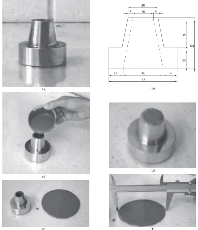
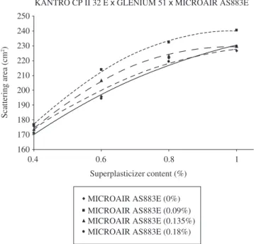
Table 1 presents the used binders. By its turn, Figures 2 and 3 illustrate the Kantro tests and their respective graphs, from which maximum contents of superplasticizer and incorporated air additive for the studied concrete were defined.
Concerning the aggregates, grinds and form index were studied. At the same time, the faults in each one were corrected. Table 2 dis-plays data about the coarse and small aggregates employed.
(a)
(c)
(e) (f)
(d) (b)
14 40
68
14 30
20
5 5
35
25 60
The form index of coarse aggregates was analyzed by determining the volumetric coefficient, which determines the aggregate spherecity, what means the relation between their dimensions. The volumetric coefficient varies from 0.2 to 1. The minimum value describes the elongated aggregate (i.e. the smallest dimension is 1.8 times bigger than the smallest dimension) and the maximum value is equivalent to a spherical aggregate. The volumetric coefficient of the crushed composition (1-19 mm) and the intermediate crushed composition (12.5 mm) was calculated as 0.2. This value of volumetric coefficient characterizes elongated aggregates. In face of that, it was detected the necessity of correcting the properties of the elongated form, which subjected the aggregate to bending (similarly to a bi-supported beam) and to grooves in the material. As a result, the mixing cannot be per-formed or becomes a difficult process. For solving that, aggregates were doped with silica fume, what strengthens the aggregate surface and makes it behave as a continuously supported beam (Figure 4).
The chosen method for doping aggregates was blending coarse aggregates with silica fume and 10% of mixing water before adding other materials in the concrete dosage.
A way to evaluate the small aggregate angularity may be to con-sider the angularity number. This is obtained by subtracting 67 from the whole percentage of solid content found in a container filled with aggregates following an established procedure. In addition to this, it is necessary to control the employed particles size with accuracy. Number 67 represents the % of solid volume of the most spherical aggregate while the angularity number measures the % of extra voids
in the spherical aggregate. The higher the number, the more angular the aggregate - this number generally ranges from 0 to 11.
The angularity number obtained from criteria proposed by Liborio7 was –1. This shows that the number of voids of the used aggregate is 1% smaller than a spherical aggregate due to the obtained wrapping.
3.3. Dosage
Dosages from two mixtures were prepared: 1) concrete with 6 ± 1% of incorporated air and 2) concrete without incorporated air. They were based on the qualitative analysis of the HPC (for low temperature environments) constituents: binders, additives, additions and aggregates
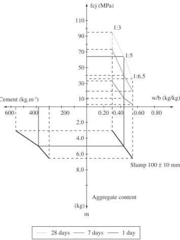
Ratios 1: m, m defined as the total number of aggregates and water/binder obtained by the dosage abacus (Figure 5) whose deter-mination was a result of the process proposed by Helene and Terzian11 and adapted by Liborio7.
This method consists of dosing three mixtures 1: m which will supply relative data to the cement consumption, water/binder ratio and mechanic resistance. Analyzing these three features in each property makes possible to trace the curves of each one of these parameters, from which the dosage abacus is composed.
Since the materials are the same for the three features, the mortar content is determined for the first dosed mixture and all the other mixtures are produced with the same consistency. In accordance with the application of the concrete, the consistency factor was determined by a slump test (NBR NM 67:1998)12 and this was adopted. During this research it was 100 ± 10 mm.
Two procedures can be adopted for this dosage method: 1) to fix the water/binder ratio or 2) to fix the dosage of additives (superplasti-cizer and incorporating air). The same superplasti(superplasti-cizer and incorporat-ing air content were adopted durincorporat-ing the dosage performincorporat-ing.
The choice of the superplasticizer content was made by analyzing the Kantro test, adopting for the initial dosage the saturation point. However, this value must be adjusted to the properties intended for the concrete, such as: consistency, durability and permeability. In
Table 1. Characteristics of the binders used for the concrete studied.
Binders Characteristics
ρ (g/cm3) Specific Surface
BET (cm2/g)
Composition
Portland cement CP II 32 E 3.04 3316 C2S -20%; C3S-56.7%;
C3A-10.1%, C3AF – 5.6%
Silica fume 2.16 20000 95% SiO2
Source: Silva10
KANTRO CP II 32 E x GLENIUM 51 x MICROAIR AS883E
160 170 180 190 200 210 220 230 240 250
0.4 0.6 0.8 1
Superplasticizer content (%)
Scattering area (cm
2)
MICROAIR AS883E (0%) MICROAIR AS883E (0.09%) MICROAIR AS883E (0.135%) MICROAIR AS883E (0.18%)
Figure 3. Kantro Test – cement CP II 32 E and superplasticizer Glenium 51 and air incorporated microair AS883E. Source: Lima9.
(a) (b)
Water Aggregate
face of these questions, it was determined a content of 0.5% for the mixtures without air incorporating agent. Next, for the mixtures with an air incorporator, the superplasticizer content was adapted to obtain the consistency of 100 ± 10 mm and the total volume of air at 6 ± 1%. Then, the contents of 0.25% of superplasticizer and 0.045% of air incorporator were set through several experiments. Finally, incorporated air content was adjusted using the gravimetrical method regulated by NBR 9833:198713.
Besides the analysis of each material, several alternatives regard-ing the sequence of mixture of the materials were carried out. Thus, the most suitable for this case study can be described according to the following stages, based on studies from Liborio and Castro8:
1) Mixture of coarse aggregates with silica fume and 10% of mixing water, blending for 2 minutes;
2) Addition of the small aggregate, Portland CP II 32 E cement, 70% of mixing water blending for 5 minutes;
3) Addition of the superplasticizer and air incorporator, for con-crete with incorporating air and 10% of mixing water, blending for 2 minutes;
4) Addition of 10% of mixing water, blending for 2 minutes. As we observed, this mixing sequence was suitable for doping coarse aggregates. More than this, it provided enough time for the beginning of the hydration reaction of the Portland cement. After that, superplasticizer and air incorporator were added, leading the additives to the surface of the binders which had already been absorbed in the aggregate walls. This procedure reduces the waste of tensoative volume while it is involved in aggregates not covered with cement paste.
From the data obtained in the dosage, the dosage abacus in Figure 5 was outlined. Based on that, the definitive feature for the concrete without incorporated air and for the concrete with incorpo-rated air was selected.
Cement (kg.m-3)
fcj (MPa)
w/b (kg/kg) 110
90
70
50
30
10
2.0
4.0
6.0
8.0
(kg) m
Aggregate content
Slump 100 ± 10 mm
600 400 200 0.20 0.40 0.60 0.80
1:3
1:5
1:6.5
28 days 7 days 1 day
Figure 5. Dosage abacus to determine feature of the HPC for environments at low temperatures. Source: Lima9.
Table 2. Description of coarse and small aggregates.
Characteristics Aggregates
Sand Crushed stone (19 mm) Crushed stone (12.5 mm)
ρ (g/cm3) 2.63 2.88 2.88
Dmax (mm) 4.8 19 12.5
Fineness modulus 2.3 6.59 6.15
Absorption (%) - 0.3 0.3
Volumetric coefficient - 0.2 0.2
Angularity number –1% -
-Source: Lima9.
Table 3. Features for the HPC study in environments with low temperatures.
HPC submitted at low temperatures
Concrete characteristics Concrete without incorporated air Concrete with incorporated air
1:M 1:5
-1:a:p:water/binder 1:2.36:2.64:0.42
-% S.P. 0.5 0.25
% IAR* - 0.045
Incorporated air content (%) 2 7
Cement content (kg/m3) 384 379
Mortar ratio (%) 56
-Slump (mm) 100 ±10
The specific mass of the concrete without incorporated air was ρ = 2.46 g/cm3 and for the concrete with incorporated air it was
ρ = 2.32 g/cm3. The consistency of both concrete tested at low temperatures was the same, although the workability of the concrete with incorporated air was better. This fact can be attributed to the presence of air bubbles that facilitate the mixture, the launching and the densification of the concrete. These characteristics of the concrete with incorporated air were confirmed while molding cylindrical specimens, mainly the prismatic specimens.
Soon after the molding, the exposed surface of the specimens was saturated by water and covered by a plastic wrap in order to prevent plastic, autogenous and drying retractions. Concretes were cured in a humid chamber after the unmolding process. The cylindrical specimens were cured by the 1st, 7th and 28th days when they were tested to determine the resistance to compression and the prismatic specimens were cured for 28 days.
The mortar content† was determined at 56%. At this point, mortar can get a cohesive mixture, have a good superficial finish and be easily handled with the materials employed in this study.
Since the early beginnings of the HPC project, some parameters were established: consistency, dosage of additives, binder composi-tion, mortar content, cement consumpcomposi-tion, ratio water/binder and ratio 1: m. Then, according to these parameters, the features expected at concrete exposed to low temperatures were defined, as shown in
The results of the compressive strength tests for this concrete are presented in Table 4.
3.4. Tests to determine the natural frequency of vibration
Determining the natural frequency of vibration in concrete speci-mens was performed according to ASTM C215-9115 (Standard test method is basic transverse, longitudinal and torsional frequencies of concrete specimens) recommendations using the Resonance for Impact method. The equipment necessary for performing the test was a piezoelectric accelerometer (Brüel & Kjaer mark, model 4383), a small hammer and an acquisition and data analysis computerized system, by Vishay manufacturer, model System 6000. The specimens were supported by the nodal points so that they could vibrate freely. Metallic springs with natural frequency lower than the frequency found in the specimens were employed. The vibration caused by ham-mer impact was measured by the accelerometer, fixed by a magnet on a metallic plate previously glued to the specimens. Signals with an acquisition rate of 10 kHz were recorded.
Piezoelectric accelerometer is generally used to measure vibra-tions, due to its small size, good sensitivity to measurements and capacity to identify a wide range of vibration frequencies. They are also self-generating signals and they do not need any power supply. Basically, they consist of a base, a piezoelectric crystal and a seismic mass, as shown in Figure 6. The piezoelectric crystal con-tains molecules with asymmetric electric charge distribution. When pressure is applied, the crystal deforms and a relative movement of positive and negative charges inside of the crystal takes place. As a result, electric charges with opposite signals are produced on the two surfaces of the crystal. Thus, when the crystal is deformed by mechanical force, it generates an electric signal proportional to its deformation.
Inside of the accelerometer, the seismic mass always compresses the crystal. So, during vibration, this compression force can increase or diminish, depending on the intensity and the direction of the vibra-tion, generating a signal (electric charge) that can be related (using calibration) to the seismic mass acceleration. Then, the electric signals the accelerometer are sent to a data acquisition system, converted to †Mortar content is defined as α = (1+a)/(1+a+p), where α is mortar content, “a” is the ratio of small aggregate and “p” is the ratio of coarse aggregate.
acceleration values due to the time, registered and processed in order to obtain the natural frequencies.
Through the processing, the acceleration amplitude signal in the time domain is converted into the frequency domain using the Fast Fourier Transformer algorithm (FFT - Fast Fourier Transformer). This way, acceleration amplitude signal due to time, that is a periodic signal, is written as a sum of the harmonic functions of sine and co-sine. Thus, obtaining the transversal, longitudinal and torsional frequencies depends of an appropriate location of the superficial ac-celerometer on the specimens.
For this research, eighteen specimens were used: 9 in concrete with incorporated air and 9 in concrete without incorporated air. They were all tested to determine the natural frequency. In each series, eight specimens were kept in a cold chamber. At the same time, one speci-men was left at room temperature. Doing that allowed comparing the natural frequencies obtained from concrete exposed to low tempera-tures and from concrete under normal temperature conditions.
The cooling curve of the specimens is illustrated in Figure 7. The cooling rate was calculated at –0.11 °C/min.
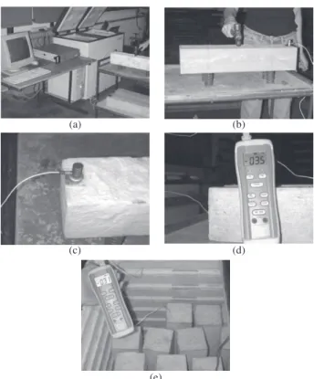
Figure 8 shows the test to determine the natural transversal fre-quency of the specimens.
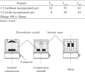
Table 4. Compressive strength for the concrete exposed to a temperature of –35 °C.
Compressive strength (MPa)
Feature fck1 fck28 fck63
1:5 (without incorporated air) 10 53 61
1:5 (with incorporated air) 8 38 43
Slump 100 ±10mm Source: Lima9.
Shear Compression
strength Connector
Isolated compression
Piezoelectric crystal Seismic mass
Figure 6. Dosage abacus to determine feature of the HPC for environments at low temperatures. Source: Lima9.
Freezing curve
40 30 20 10 0 10 20 30
0 100 200 300 400 500 600
Time (minutes)
Temperature (°C)
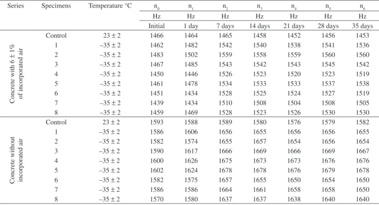
The values of the natural frequencies were obtained by reading a Cartesian coordinate system (X, Y), made from a signal conversion system. The abscissa (x-axis) represents the natural frequency and the ordinate (y-axis) the amplitude. Figure 9 displays the corresponding graphs to the initial, intermediate and final readings. It also shows what was observed after the thawing of specimen from each series. The results observed during these tests are shown in Table 5, where the two series can be seen: concrete with incorporated air and without incorporated air. The specimen of each series left outside of the cold chamber is identified by the acronym (CTRL). This procedure makes possible to examine the natural frequency differences found in concrete exposed to low temperatures and to normal temperature conditions.
Figure 10 shows the evolution of the natural frequency for each specimen in a graph.
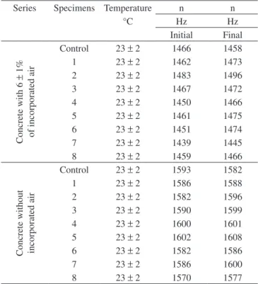
After natural frequency values became stable, a reading was taken on the thirty-fifth day of low temperature exposure. Next, the specimens were left at room temperature until they recovered thermodynamic balance, that is, reach room temperature. Table 6 shows the natural frequency values of the concrete specimens at room temperature before and after the period they were exposed to low temperatures.
The results in Table 6 are represented graphically in Figure 11. These results proved that, even under temperatures of –35 °C, the integrity of the specimens from both concrete (with incorporated air and without incorporated air) was preserved.
3.5. Discussion of the results
According to the results concerning the natural transversal frequency for the specimens, made from concrete with
incorpo-(a) (b)
(c) (d)
(e)
Figure 8. a) Processing system of signals to read the natural frequency; b) test of specimens to determine the natural frequency; c) Detail of the accelerom-eter (signal capturer); d) Thermomaccelerom-eter to gauge the internal temperature of specimens; and e) cold chamber. Source: Lima9.
Natural frequency - concrete without incorporeted air - initial measurement
0.00 0.01 0.02 0.03 0.04 0.05 0.06 0.07 0.08
0 1000 2000 3000 4000 5000 6000
Natural frequency (Hz)
Amplitude (m)
Natural frequency - Concrete with incorporated air initial measurement
0.00 0.05 0.10 0.15 0.20
0 1000 2000 3000 4000 5000 6000
Natural frequency (Hz)
Amplitude (m)
Natural frequency - Concrete without incorporated air - after 35 days in cold
chamber
0.00 0.05 0.10 0.15 0.20 0.25 0.30
0 1000 2000 3000 4000 5000 6000
Natural frequency (Hz)
Amplitude (m)
Natural frequency - Concrete with incorporated air - after 35 days in cold
chamber
0.00 0.05 0.10 0.15 0.20 0.25
0 1000 2000 3000 4000 5000 6000
Natural frequency (Hz)
Amplitude (m)
(a) (b)
(c) (d)
Table 5. Natural frequency obtained for the specimens at various ages.
Series Specimens Temperature °C n0 n1 n2 n3 n4 n5 n6
Hz Hz Hz Hz Hz Hz Hz
Initial 1 day 7 days 14 days 21 days 28 days 35 days
Concrete with 6
±
1%
of incorporated air
Control 23 ± 2 1466 1464 1465 1458 1452 1456 1453
1 –35 ± 2 1462 1482 1542 1540 1538 1541 1536
2 –35 ± 2 1483 1502 1559 1558 1559 1560 1560
3 –35 ± 2 1467 1485 1543 1542 1543 1545 1542
4 –35 ± 2 1450 1446 1526 1523 1520 1523 1519
5 –35 ± 2 1461 1478 1534 1533 1533 1537 1538
6 –35 ± 2 1451 1434 1528 1525 1524 1527 1519
7 –35 ± 2 1439 1434 1510 1508 1504 1508 1505
8 –35 ± 2 1459 1469 1528 1523 1526 1530 1530
Concrete without incorporated air
Control 23 ±2 1593 1588 1589 1580 1576 1579 1582
1 –35 ± 2 1586 1606 1656 1655 1656 1656 1655
2 –35 ± 2 1582 1574 1655 1657 1654 1656 1654
3 –35 ± 2 1590 1617 1666 1669 1666 1669 1667
4 –35 ± 2 1600 1626 1675 1673 1673 1676 1676
5 –35 ± 2 1602 1624 1678 1678 1676 1679 1678
6 –35 ± 2 1582 1575 1657 1655 1650 1654 1650
7 –35 ± 2 1586 1586 1664 1661 1658 1658 1650
8 –35 ± 2 1570 1580 1637 1637 1638 1640 1640
n = natural frequency; Source: Lima9.
Natural frequency - Concrete without incorporated air submitted at 35 °C
1350 1400 1450 1500 1550 1600 1650 1700
1 2 3 4 5 6 7 8
Specimens
n0 Initial
n1 1 day
n2 7 days
n3 14 days
n4 21 days
n5 28 days
n6 35 days
Natural frequency (Hz)
(a)
Natural frequency - Concrete with incorporated air submitted 35 °C
1350 1400 1450 1500 1550 1600
1 2 3 4 5 6 7 8
Specimens (b)
rated air and without incorporated air, it can be concluded that both demonstrated durability when subjected to –35 °C temperature environments.
However, deformations were registered throughout the freez-ing period. These deformations were caused by expansions and contractions but they did not damage the concrete. As the tests have demonstrated, concrete elastic properties were preserved until the end of the period, as well as after the specimens thawing.
By interpreting the concrete behavior throughout this test program, it became possible to relate deterioration mechanisms to freezing action, attributed to the generation of hydraulic pressure and
the diffusion of water-gel and capillary water, based on the theory proposed by Powers3 and Powers and Helmulth2.
The specimens were constantly exposed to the cooling rate of 0.11 °C/min (the temperature of –35°C), which was considered slow. Moreover, the temperature was less than necessary to freeze water in normal conditions of temperature and pressure. The aforemen-tioned are factors that infer the phenomenon of diffusing water-gel and capillary water to the behavior of the concrete which has been evaluated.
The previous conclusion is supported by the fact that all the specimens contracted initially. Actually, the specimens with incor-porated air showed expansion just after the 21st day of exposure while the specimens without incorporated air started expanding on the 7th day.
Therefore, in the beginning, besides the thermal contraction, the depletion of water-gel derived from the diffusion phenomenon, caused the observed contraction. By its turn, the time required for equalizing the free energy of water-gel and the capillary ice can be pointed as a reason for the different contraction period verified in concrete with incorporated air and concrete without incorporated air.
To illustrate, in the concrete with incorporated air, the proximity of the water film absorbed in the gel, with the air voids, made the balance of energy levels being reached in a quicker way, preventing the capillary ice growth and, consequently the paste break-up.
In the concrete without incorporated air, the depletion of water-gel to capillaries smaller than air bubbles results in higher superficial tension. Consequently, there is an increase in the energy level of the capillary ice, what helps its growth, causing the capillary wall deformation.
Even the presence of air voids in the concrete with incorporated air was not enough to stop the ice crystals growing or the hydraulic pressure resulted from the water-gel depletion to the capillaries and air voids. Then, the expansion could not be avoided although this fact has been harmless to the good performance of the concrete when frozen (i.e. the deformations did not affect the specimens stiffness). In order to suppress any residual deformation (expansion) and to assure that contraction took place from the beginning to the end of the freezing period, two procedures were proposed. The first is the improvement of the voids distribution and it should be applied to concrete with incorporated air. The second, related to concrete without incorporated air, is the mortar reinforcement to increase the tensile strength of the concrete. This last one should be checked, though.
The cooling rate, target temperature and constant temperature condition must be recognized as significant factors in the predomi-nance of the diffusion phenomenon. On the other hand, there are other important aspects that were really effective for preventing damage caused by the generated hydraulic pressure in the concrete studied.
One of these aspects is the amount of frozen water. Powers4 dem-onstrated that the value 0.25 is the maximum concrete ratio water/ binder in which concrete without incorporated air resists freezing. Lang and Ward15, amongst others, also confirmed this assumption. However, the ratio water/binder of 0.42, proposed at this research, was higher than the one suggested by the previous authors. Even the concrete without incorporated air was durable when frozen, showing the efficiency of the hydration process, since it consumed the frozen water. Moreover, the pore refinement was certainly a considerable factor concerning concrete durability when frozen. This is because pore refinement causes an increase in the superficial tension in the water stored or led to these voids, which means a lower temperature of freezing.
Although the pore refinement can be attributed to mineral ad-ditions (i.e. active silica), it is important to emphasize that the ce-ment bulk reinforcece-ment was due to the biggest amount of C-S-H Table 6. Natural transversal frequency of prismatic specimens 10 x 10 x 50 cm
after 35 days of exposure to low temperatures.
Series Specimens Temperature n n
°C Hz Hz
Initial Final
Concrete with 6
±
1%
of incorporated air
Control 23 ±2 1466 1458
1 23 ±2 1462 1473
2 23 ±2 1483 1496
3 23 ±2 1467 1472
4 23 ±2 1450 1466
5 23 ±2 1461 1475
6 23 ±2 1451 1474
7 23 ±2 1439 1445
8 23 ±2 1459 1466
Concrete without incorporated air
Control 23 ±2 1593 1582
1 23 ±2 1586 1588
2 23 ±2 1582 1596
3 23 ±2 1590 1599
4 23 ±2 1600 1601
5 23 ±2 1602 1608
6 23 ±2 1582 1586
7 23 ±2 1586 1600
8 23 ±2 1570 1577
Initial frequency x Final frequency (thaw) (after 35 days of exposure to freezing)
1350 1400 1450 1500 1550 1600 1650
Frequency (Hz)
CTRL 1 2 3 4 5 6 7 8
Concrete with incorporated air (initial)
Concrete with incorporated air (thaw)
Concrete without incorporated air (initial)
Concrete without incorporated air (thaw)
produced. This resulted from the pozzolanic reaction activated by these additions – Melo16. This property was also favorable to a longer freezing period.
Progress in concrete technology, made possible by binder as-sembling, favors the concrete performance even under adverse conditions. This is an unquestionable fact and of great importance for effective performance, due to the difference between the avail-able binders nowadays and in the past. The binders, employed by Powers to develop the presented theories, used to freeze all the stored water (i.e. capillary water and water contained in the cavities in concrete with a water/binder of 0.30 at –15 °C. In 1998, Ukamoto and Uomoto17, by their turn, produced mortars with water/binder of 0.30 at a temperature of –20 °C, and showed that the water just froze in pores bigger than 0.05 μm.
The stiffness (i.e. measured by the natural transversal frequency) in concrete with and without incorporated air exposed to a temperature of –35 °C was preserved. Generated hydraulic pressure, attributed to the movement of capillary water, could be harmful but any dam-age to the concrete stiffness was registered. This is evidence that the pores were refined. Based on Ukamoto and Uomoto19, it can be concluded that a great amount of the pores in this concrete is smaller than 0.05 μm.
Similarly, the hydraulic pressure phenomenon was minimized by the advanced degree of hydration, reached after a 28 day curing period in a humid chamber. Furthermore, the actions to prevent the plastic, drying and autogenous retractions - as soon as the specimens were taken out from the molds and put in the humid chamber - were essen-tial for the durability of the concrete exposed to low temperatures.
Other factors were relevant to obtain concrete durability at low temperatures. They were important when developing cohesive con-crete, little permeable and with some improvement in the interface paste/aggregate zone. These were obtained by a suitable method of dosage and concrete mixing.
4. Conclusions
The result of the experiment of freezing concrete with and with-out incorporated air showed that both were resistant to environments in these conditions, demonstrating that the concrete is an excellent alternative material to build storage systems and conserve food.
The result of the experiment on freezing concrete with and with-out incorporated air showed that both were resistant to environments in these conditions. This demonstrated the concrete is an excellent alternative material to build storage and conservation food systems.
The concrete without incorporated air was resistant to the dam-age caused by freezing described and demonstrated by Powers2 and Powers and Helmuth3. It also showed that the air incorporation is unnecessary as well as the limitation of the ratio w/b (water/binder) at 0.24 in concrete developed according to techniques proposed by Liborio7 and proved by the group of researchers at the Laboratory of Advanced Materials of Cement at the School of Engineering in São Carlos at the University of São Paulo.
Acknowledgments
The authors would like to thank the group of researchers at the Laboratory of Advanced Materials of Cement at the School of Engi-neering in São Carlos at the University of São Paulo, the University
of São Paulo and CNPq - National Counsel of Technological and Scientific Development.
References
1. Powers TC. A working Hypothesis for further studies of frost resistance of concrete. Journal of the American Concrete Institute. Michigan. 1945;
16(4):245-273.
2. Powers TC., Helmuth RA. Theory of volume changes in hardened Portland-cement past during freezing. Proceedings Highway Research Board. 1953; 32:285-297.
3. Powers TC. The air requirement of frost-resistance concrete. Proceedings Highway Research Board. 1949; 29:184-211.
4. FÉDERATION INTERNATIONALE DU BÉTON. Structural Concrete: textbook on behavior, design and performance v. 2. Switzerland: FIB; 1999. 305p.
5. INSTRUCCÍON DE HORMIGÓN ESTRUTURAL. Hormigón Estructural: normas técnicas 5. Madrid: EHE; 2001. 475p.
6. Mehta PK., Monteiro PJM. Concreto: estrutura, propriedades e materiais.
São Paulo: Pini; 1994. 573p.
7. Liborio JBL. Concreto de alto desempenho – uma tecnologia simples para produção de estruturas duráveis. Revista Tèchene. 2003.
8. Liborio JBL, Castro AL. A importância da avaliação reológica de pastas com e sem sílica ativa para produção de concretos estruturais com cimento Portland para obras marítimas. In: Seminary and Workshop for Oceanic Engineering; 2004; Rio Grande/RS. Rio Grande/RS; 2004. [Annals]. CDROM.
9. Lima SM. Concreto de alto desempenho em ambientes com baixas temperaturas. [Dissertation Mastership]. Department of Structural Engineering, EESC, University of São Paulo; 2006. 216 p + annex. 10. Silva VM. Contribuição ao estudo da carbonatação em concretos e
argamassas executados com e sem adição de sílica ativa. [Dissertation Mastership]. Inter units in Science and Materials Engineering, EESC / IQSC/ IFSC, University of São Paulo; 2002. 170 p.+ annexes. 11. Helene PRL., Terzian P. Manual de dosagem e controle do concreto. São
Paulo: Pini, 1992. 349 p.
12. ASSOCIAÇÃO BRASILEIRA DE NORMAS TÉCNICAS. NBR NM 67: 1998. Consistência pelo abatimento do tronco de cone. Rio de Janeiro:
ABNT; 1998.
13. ASSOCIAÇÃO BRASILEIRA DE NORMAS TÉCNICAS. Determinação do teor de ar incorporado em concretos pelo método gravimétrico. NBR 9833: 1987. Rio de Janeiro: ABNT; 1987.
14. AMERICAN SOCIETY FOR TESTING AND MATERIALS. Standard test method for fundamental transverse, longitudinal, and torsional frequencies of concrete specimens: C 215-91. Philadelphia: ASTM; 1991.
15. LANGAN BW., WARD MA. Freezing and thawing: comparison between non-air-entrained and air-entrained high-strength concrete. In: AMERICAN CONCRETE INSTITUTE. ACI SP-149. [S.I]: ACI; 1991. cap. 31. p. 545-560.
16. Melo AB. Influência de cura térmica (vapor) sob pressão atmosférica no desenvolvimento da microestrutura dos concretos de cimento Portland. [Thesis Philosophy Doctor]. Inter Units in Science and Materials Engineering, EESC / IQSC/ IFSC, University of São Paulo; 2000. 245p. + annexes.