*e-mail: [email protected], [email protected]
Microstructure and Mechanical Properties of
Thermal Sprayed Nanostructured Cr
3C
2-Ni20Cr Coatings
Cecilio Alvares da Cunha, Nelson Batista de Lima, Jose Roberto Martinelli,
Ana Helena de Almeida Bressiani*, Armando Guilherme Fernando Padial,
Lalgudi Venkataraman Ramanathan*
Instituto de Pesquisas Energeticas e Nucleares – IPEN,
Av. Prof. Lineu Prestes 2242, Cidade Universitaria
05508-000 São Paulo - SP, Brazil
Received: March 26, 2007; Revised: May 16, 2008
Cr3C2-Ni20Cr coatings have been used for corrosion and wear resistant applications. However, one of the shortcomings of these coatings is its low hardness, and consequent low wear resistance, for long term high temperature applications. Nanostructured coatings of many materials have exhibited higher hardness and strength compared with conventional coatings of the same material. Consequently, nanostructured coatings of other materials, including Cr3C2-Ni20Cr have been attempted to enhance overall performance. In this study the effects of high energy milling parameters on Cr3C2-25(Ni20Cr) powder characteristics as well as the microstructure and mechanical properties of nanostructured Cr3C2-25(Ni20Cr) coatings formed by high velocity oxygen fuel (HVOF) spraying have been evaluated. The average particle size and crystallite size of milled Cr3C2-25(Ni20Cr) powders decreased with increase in milling time and this decrease was more pronounced in nitrogen compared to that in hexane. This difference has been attributed to a cushioning effect in the latter medium. The coatings prepared with milled Cr3C2-25(Ni20Cr) powders had a more uniform microstructure, were harder and had higher relative fracture toughness compared with coatings prepared with as-received powders.
Keywords: Chromium carbide, nanostructured coating, mechanical milling, thermal spraying
1. Introduction
Coatings containing chromium carbide particles distributed in a nickel-chromium alloy matrix (Cr3C2-NiCr system) have been used for corrosion and wear resistant applications. These coatings can be used in corrosive environments at temperatures (up to 900 °C), much higher than that at which the harder WC-Co coatings can be used. The latter undergo decarburization to W2C or to W upon extended exposure to high temperatures and to degradation of mechanical properties1,2-5. However, one of the shortcomings of Cr
3C2-NiCr coatings is its lower hardness and lower wear resistance, compared to WC-Co coatings6. This has lead to attempts at producing nanos-tructured Cr3C2-NiCr coatings for improved hardness and overall performance. During the last decade, thermal sprayed coatings of various materials prepared with nanocrystalline feed stock have ex-hibited higher hardness, strength and corrosion resistance compared to those prepared with conventional feed stock powders of the same materials7-10. Several methods have been used to prepare thermal sprayed nanostructured coatings. These include direct spraying of nanosized powders with or without gaseous or liquid precursors and also spraying of specially designed alloys with low critical cooling rates11-14. In the latter method, upon spraying, the alloys with low critical cooling rates become amorphous, and the coating is then devitrified by heating10,14. The most widely used method consists of high energy mechanical milling of conventional powders to obtain nanocrystalline powders, which are subsequently agglomerated to the required size prior to spraying15-20.
Mechanical milling enables large quantities of nanostructured materials to be produced and during milling the powder grains are continuously refined by cold welding and fracturing21-24. Nanostruc-tured composites consisting of hard particles and a metal binder, such as Cr3C2-NiCr or WC-Co, have been prepared by mechanical
milling5,25,26. Milling of Cr
3C2-NiCr has been done in a variety of environment. The environment contributes mainly to reduction of contaminants in the powders, to control powder temperature and to control powder characteristics. The milling environment could be gaseous (argon, nitrogen, hydrogen), liquid (liquid nitrogen, ac-etone, hexane) or solid (stearic acid)26. Powders of Cr
3C2-NiCr have been milled mainly in liquid hexane [H3C (CH2)4CH3]26. Data about milling of Cr3C2-NiCr powder in gaseous nitrogen is scarce. This paper presents and compares the effects of high energy mechanical milling of Cr3C2-25(Ni20Cr) powder in liquid hexane and gaseous nitrogen. The influence of milling time on Cr3C2-25(Ni20Cr) powder characteristics as well as the microstructure and mechanical proper-ties of nanostructured Cr3C2-25(Ni20Cr) coatings prepared using high velocity oxygen fuel (HVOF) spraying of the milled powders are also presented.
2. Materials and Methods
2.1. Milling of powders
and determine its composition. X ray diffraction (XRD) analysis of the as-received and milled powders was carried out to determine the crystallite sizes. The main peak of Cr3C2 in the diffraction pattern, in conjunction with the Scherer Equation 1 was used to determine the average crystallite size of the powders27,28. This equation relates crystallite size (D) and the full-width at half-maximum (FWHM), referred to as Δ (2θ) of XRD reflections.
D = 0.9λ /Δ (2θ) cosθ (1)
where λ is the wavelength (in the case of a Cu target, λ = 0.15406) and θ is the diffraction angle. The use of this equation is based on the physical origin of broadening of the XRD reflections being associated with the small grain size only. The true peak broadening Δ (2θ) can be obtained using Equation 2:
Δ (2θ) = [(Δ(2θ)h)2 – (Δ(2θ) g)
2]1/2 (2)
where Δ(2θ)h is the FWHM of the measured profile and Δ(2θ)g is the FWHM of the profile from the standard sample for the same reflec-tion. The grain size thus obtained is volume averaged in a direction perpendicular to the diffraction plane.
2.2. Thermal sprayed coatings
The Cr3C2-25(Ni20Cr) powder in the as-received condition and that milled for 4 hours in nitrogen were used as feed stock for ther-mal spraying coatings on AISI 310 specimens 50 x 20 x 2 mm using the high velocity oxygen fuel (HVOF) process. The average particle size of the milled powders was 11 µm, close to the lower limit of acceptable particle sizes for HVOF spraying. The average coatings thickness was 200 µm. The spraying parameters and gun to specimen distance were identical while spraying the two types of powders. The microstructure and phase composition of the coating cross-sections were examined and determined respectively, with a SEM/EDS system. The hardness of the coatings was determined across its sections, us-ing loads of 500 and 1000 g. The average hardness was determined from five indentations in the middle of each of the coating sections, away from the two interfaces.
3. Results and Discussion
3.1. The milled powders
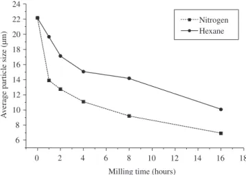
Figure 1 shows the variation in average particle size of Cr3C2 25-(Ni20Cr) powders as a function of milling time in hexane and in
gaseous nitrogen. In the two milling media, the average particle size decreased with increase in milling time. The decrease in average particle size with milling time in nitrogen was significant compared to that in hexane. Reductions in Cr3C2-25(Ni20Cr) powder particle size to 5 µm upon milling in hexane have been reported5, 26. However, in this study the particle size of powders milled for the same duration in hexane was only 10 µm. The marked reduction in particle size of powders milled in nitrogen compared to that milled in liquid hexane as well as the differences in the particle size of powders milled in hexane for similar duration, between that reported5, 26 and in this study was further investigated. This consisted of measuring the particle and crystallite sizes of Cr3C2-25(Ni20Cr) powders milled separately for 8 hours with 10, 50 and 100 ml of liquid hexane in the ZOZ mill. In these measurements, the amount of powder and other milling parameters were maintained identical. Particle size variations as a function of hexane volume are shown in Table 1. Significant decrease in particle size with reduction in the amount of hexane indicate a cushioning effect in liquid hexane compared to that in nitrogen as the milling medium in the initial experiments.
X ray diffraction patterns of the milled powders were used to determine the crystallite sizes. Figure 2 shows a typical diffraction spectrum of Cr3C2 -25(Ni20Cr) powder milled in nitrogen. The dif-fraction peaks were identified and the Cr3C2 reflection at 2θ≈ 39°was used to determine the crystallite size with the Scherrer Equation 1 mentioned earlier. Aware that micro-deformation and instrument and/ or measurement conditions also affect peak broadening, Figures 3a and 3b were plotted. Figure 3a reveals fitting of the Gaussian curve, corresponding to micro-deformation, and Figure 3b, the fitting of the Lorentzian curve, attributable to crystallite size on the selected peak in the diffraction pattern. The peak profile can be seen to be mainly Lorentzian, indicating that peak broadening was due to crystallite
0 2 4 6 8 10 12 14 16 18
6 8 10 12 14 16 18 20 22 24
Milling time (hours)
A
v
erage particle size (µm)
Nitrogen Hexane
Figure 1. Effect of milling medium and duration on Cr3C2-25(Ni20Cr)
powder particle size.
30 40 50 60 70 80 90
0 50 100 150 200 *# * **** * * * * * * * * * * * * * * * * * Intensity a.u.
Angle (2θ
#
* Cr3C2
# NiCr
Figure 2. X ray diffractogram of Cr3C2-25(Ni20Cr) powder milled for 8 hours
in nitrogen.
Table 1. Effect of hexane volume on average particle size of milled
Cr3C2 -25(Ni20Cr) powders.
Cr3C2 -25(Ni20Cr) powder Average powder particle size (µm)
As received 35.79
Milled with 100 mL hexane 10.00
Milled with 50 mL hexane 5.00
size. The average crystallite size of the particles was determined using the Scherrer Equation 1 after subtracting for peak broadening due to the instrument. This technique permits measurement of average crystallite sizes of up to 150 nm27.
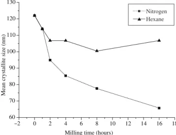
The average crystallite size of Cr3C2 in the milled powders de-creased with increasing milling time as shown in Figure 4. The
aver-age crystallite size decreased from 125 nm to 65 nm after 16 hours of milling in nitrogen. The reduction in average crystallite size of Cr3C2 as a function of milling time in hexane was less and this could be also attributed to the cushioning effect of the liquid hexane, as cor-roborated by data shown in Table 2 in which crystallite size decreases with decrease in the volume of hexane in the mill.
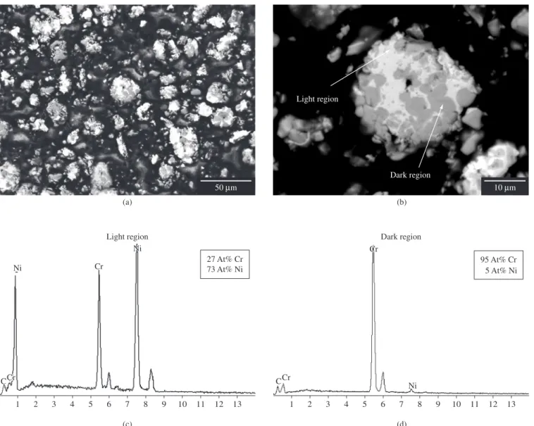
The as-received and milled powders were examined in the SEM. Microscopic features, other than powder sizes were similar in both the as-received and the milled powders. The Cr3C2 particles were embedded in the Ni-Cr alloy phase. Figures 5a and 5b reveal micro-graphs of the powders milled in nitrogen for 4 hours. Figure 5b is a higher magnification micrograph of a region in Figure 5a. The energy dispersive spectrum shown in Figures 5c and 5d are of the dark and light regions in the powder particle shown in Figure 5b. The dark regions with 95 at % Cr were Cr3C2 particles and the light regions, the Ni-Cr alloy phase.
3.2. The HVOF sprayed coatings
The microstructures of cross-sections of coatings prepared with as-received and milled Cr3C2-25(Ni20Cr) powders are shown in Figure 6. The coating with the milled powder (nanostructured coating) contained fewer pores, was more uniform and dense as shown in Figures 6c and 6d, compared to the coating prepared with as-received powders that are shown in Figures 6a and 6b. The higher magnification micrographs in Figures 6b and 6d are of regions shown in Figures 6a and 6c. The very bright regions in the micrographs in Figures 6a and 6c are contaminants. The light, light grey and dark grey regions (shown with arrows) were analyzed using EDS in the SEM. This analysis revealed large Ni peaks and very small Cr peaks (similar to that shown in Figure 5c) on the light region indicating it to be the Ni-Cr alloy phase. The dark grey regions rendered large Cr peaks in the EDS spectrum indicating it to be the Cr3C2 phase. The light grey regions contained the two phases, Cr3C2, Ni-Cr, indicating it to be a composite phase. Similar observations have been reported29. The hardness test data are shown in Table 3. The hardness of the nanostructured coatings was higher than that of the coatings with as-received powders. Cracks emanating from the indents were observed in the two types of coatings and are indicated in the micrographs of Figure 7. The cracks seen in the coatings obtained with the as-received powders were longer and wider. The cracks in both types of coatings were mainly parallel to the substrate. Similar findings have been reported5,10. The crack lengths were used to qualitatively compare
38 40
0 200 400 600 800 1000
Intensity a.u.
Angle (2θ Gauss fit - r2 = 0.982
38 40
0 200 400 600 800 1000
Intensity a.u.
Angle (2θ Lorentz fit - r2 = 0.999482
Figure 3. a) Gaussian fit and b) Laurentzian fit on the main Cr3C2 peak of
the diffraction spectrum of Cr3C2-25(Ni20Cr) powder milled for 8 hours in
nitrogen.
Nitrogen Hexane
–2 0 2 4 6 8 10 12 14 16 18
60 70 80 90 100 110 120 130
Mean crystallite size (nm)
Milling time (hours)
Figure 4. Average crystallite size of Cr3C2-25(Ni20Cr) powder as a function
of milling medium and milling time.
Table 2. Effect of hexane volume on average crystallite size of milled Cr3C2
–25(Ni20Cr) powder.
Cr3C2 powder Average crystallite size (nm)
As received 78
Milled with 50 mL of hexane 54
Milled with 10 mL of hexane 49
Table 3. Microhardness of HVOF coatings with as-received and
nanocrystal-line Cr3C2–25(Ni20Cr) powder.
Hardness of HVOF coatings with As-received
powder
Nanocrystalline powder
Coating thickness (µm) 190 214
the fracture toughness of the coatings prepared with as-received and milled powders. This comparison was based on reported linear correlations between hardness and resistance to cracking in these types of coatings7. This indicated that the relative fracture toughness of the nanostructured coating was higher. Some of the cracks were along the phase boundaries in the coatings. There were fewer cracks in the nanostructured coating, due probably to composite formation and higher hardness.
4. General Discussion
The hardness of thermal sprayed coatings is affected by the tech-nique as well as characterisctics of the feed stock2,3,30,31. In the HVOF technique, the particle velocity is high and thermal energy low, and this leads to high hardness32. It has been reported that nanostructured materials often exhibit higher hardness compared to corresponding conventional materials, although lower than that predicted using the classical Hall-Petch equation33-35. In this investigation also the hard-ness of nanostructured Cr3C2-25(20NiCr) coating was higher than that of the coating prepared with as-received powders. The higher hardness of the nanostructured coatings is considered to be due to
the uniform microstructure caused by the mechanical milling proc-ess to obtain feed stock and the intrinsically high hardnproc-ess of the nanostructured material.
The indentation fracture method has been used to obtain informa-tion about the relative fracture toughness of coatings29. In this study, at 1000 g hardness test load, cracks emanating from the indents were observed in both types of coatings. These cracks were mostly parallel to the coating surface and were not present directly on the extended line of the diagonal of the indentation. Many indentation cracks were also observed along the carbide - metal binder interface in coatings prepared with the as-received powder. (Figure 7) Fewer indentation cracks were observed in the nanostructured coatings at the same hardness test load. These results indicated that crack propaga-tion within the coating had a preferred direcpropaga-tion and there was high resistance to indentation fracture in the direction perpendicular to the coating surface. The preferred direction for crack propagation could be attributed to the thermal spray process. A complete coating is produced by passing the spray torch many times across the substrate and this could result in contamination of a deposited layer prior to deposition of the next layer. Also differences in the thermal expansion
Light region
Dark region
95 At% Cr 5 At% Ni 27 At% Cr
73 At% Ni
1 2 3 4 5 6 7 8 9 10 11 12 13 1 2 3 4 5 6 7 8 9 10 11 12 13
CCrCr CCr
Cr Cr
Cr Ni
Ni Ni
Ni (a)
Light region Dark region
(b)
(c) (d)
10 µm 50 µm
Figure 5. a, b) Scanning electron micrographs of Cr3C2-25(Ni20Cr) powder milled for 4 hours in nitrogen; c, d) EDS of light and dark regions in the large
Acc.V 20.0 kV
Magn 250x
Spot 4.9
WD 10.4
100 µm Det
BSE TAFA NP 6
Acc.V 20.0 kV
Magn 1000x
Spot 4.9
WD 10.4
20 µm Det
BSE TAFA NP 6
Acc.V 20.0 kV
Magn 250x
Spot 4.7
WD 10.0
100 µm Det
BSE TAFA P 15
Acc.V 20.0 kV
Magn 1300x
Spot 4.4
WD 10.2
20 µm Det
BSE TAFA P 26
(a) (b)
(c) (d)
Figure 6. Cross-sections of HVOF coatings: a) and b) with as-received Cr3C2-25(Ni20Cr); c) and d) nanostructured Cr3C2-25(Ni20Cr).
Acc.V 15.0 kV
Magn 1000x
Spot 4.5
WD 14.5
20 µm Det
SE TAFA NP 18 1000
Acc.V 20.0 kV
Magn 1200x
Spot 4.0
WD 10.3
20 µm Det
SE TAFA P 15 I 1000
(a) (b)
Figure 7. Typical microhardness indents with 1000 g load and cracks (arrows) emanating from the indents on cross-sections of HVOF coatings of
coefficient between the carbide and alloy phases could contribute to crack propagation along the phase interface. Discontinuity in heat and mass transfer has also been cited to result in discontinuity in the coating along which cracks propagate29. Indents associated with the lower hardness test load of 500 g revealed few cracks in the coating prepared with as-received powders, and none in the nanostructured coating. These observations suggest that the nanostructured coating possesses a higher resistance to cracking or higher apparent fracture toughness relative to that of the coating prepared with as-received powders. Since abrasion resistance of a coating is related to the apparent fracture toughness, it is evident that the nanostructured Cr3C2-25(Ni20Cr) coatings have higher abrasion resistance36.
5. Conclusions
• HighenergymillingofCr3C2-25(Ni20Cr) powders in gaseous
nitrogen and liquid hexane reduced the average particle size. The reduction in particle size with increase in milling time was more pronounced in nitrogen compared with that in liquid hexane.
•The average crystallite size of the milled Cr3C2-25(Ni20Cr)
powders also decreased with increase in milling time. The average crystallite size reduction was significant in powders milled in nitrogen.
• Insuficient particle and crystallite size reductions in liquid hexane, compared to that in gaseous nitrogen are attributed to a cushioning effecting in liquid hexane.
• The microstructure of HVOF sprayed coatings of Cr3C2-25(Ni20Cr) prepared with milled powders was uniform compared with those prepared with as-received powders. • The hardness and fracture toughness of the nanostructured
Cr3C2-25(Ni20Cr) coatings were higher compared with coat-ings prepared with the as-received powders.
References
1. Mateos J, Cuetos JM, Vijande R, Fernandez E. Tribological properties of
plasma sprayed and laser remelted 75/25Cr3C2/NiCr coatings. Tribology
International 2001; 34(5):345-351.
2. Russo L, Dorfmann M. High temperature oxidation of MCrAlY coatings produced by HVOF. In: Thermal Spraying: Current status and future trends. A. Ohmori (Ed). Osaka, Japan: High Temperature Society of Japan; 1995. p. 681-686.
3. Reardon JD, Mignogna R, Longo FN. Plasma and vacuum-plasma-sprayed
Cr3C2 composite coatings. Thin Solid Films 1981; 83(3):345-351.
4. Knotek O, Elsing R, Heintz HR. On plasma sprayed WSi2 and
Cr3C2- Ni coatings. Journal of Vacuum Science and Technology 1985;
A3:2490-2493.
5. He J, Ice M, Lavernia EJ. Synthesis and characterization of nanostructured
Cr3C2-NiCr. Nanostructured Materials 1998; 10(8):1271-1283.
6. Vuoristo P, Niemi K, Makela A, Mantyla T. Abrasion, erosion of wear
resistance of Cr3C2-NiCr coatings prepared by plasma, detonation and high
velocity oxy-fuel spraying. In: Thermal Spray Industrial Applications. C.C. Berndt, S. Sampath (eds.). OH, USA: ASM International, Materials Park; 1994. p. 121-126.
7. Kear BH, McCandlich LE. Chemical processing and properties of
nanostructured WC-Co materials. Nanostructured Materials 1993;
3(1-6):19-30.
8. Lau ML, Jiang HG, Nuchter W, Lavernia EJ. Thermal spraying
of nanocrystalline Ni coatings. Physica Status Solidi A 1998;
166(1):257-268.
9. Lavernia EJ, Lau ML, Jiang HG. Thermal spray processing of
nanocrystaline materials, Nanostructured Materials. GM Chow and N.I. Noskova (eds.). Hingham, MA, USA: Kluwer Academic Publishers; 1998. p. 283-302.
10. Roy M, Pauschitz A, Bernardi J, Koch T, Franek F. Microstructure and
mechanical properties of HVOF sprayed nanocrystalline Cr3C2-25(Ni20Cr)
coatings. Journal of Thermal Spray Technology 2006; 15(3):372-381.
11. Zhu YC, Ding CX. Plasma spraying of porous nanostructured TiO2 films.
Nanostuctured Materials 1999; 11(3):319-323.
12. Rao NP, Lee HJ, Kelkar M, Hansen DJ, Heberlain JVR, McMurry PH, Girshik SL. Nanostructure materials production by hypersonic plasma particle deposition. Nanostructured Materials 1997; 9(1-8):129-132.
13. Kartikeyan J, Berndt CC, Tikkanen J, Wang JY, King AH, Herman H. Preparation of nanostructure materials by thermal spray processing of liquid precursors. Nanostructured Materials 1997; 9(1-8):137-140.
14. Branagan DJ, Swank WD, Haggard DC, Fincke JR. Wear resistant amorphous and nano composite steel coatings. Metallurgical and Materials Transactions 2001; 32A:2615-2621.
15. Grosdidier T, Liao HL, Tidu A. Thermal spray surface engineering via applied research. Proceedings of the First International Thermal Spray Conference; 2000 May 8-11; Montreal, Canada: ASM - Thermal Spray Society. p. 1341-1344.
16. Lau ML, Strock E, Fabel A, Lavernia CJ, Lavernia EJ. Snythesis and characterisation of nanocrystalline Co-Cr coatings by plasma spraying. Nanostructured Materials 1998; 10(5):723-780.
17. Lau ML, Jiang HG, Lavernia EJ. Thermal stability of nanocrystalline Inconel 718 and Ni prepared by high velocity oxygen fuel (HVOF) thermal spraying. Proceedings of the International Thermal Spray Conference; 1998 May 25-29; Nice, France: C. Coddet (Ed.). p. 379.
18. Lau ML, Gupta VV, Lavernia EJ. Particle behavior of nanocrystalline 316 stainless steel during high velocity oxy fuel thermal spraying. Nanostructured Materials 1999; 12(1-4):319-322.
19. Kear BH, Skadan G. Thermal spray processing of nanoscale materials. Nanostructured Materials 1997; 8(6):765-769.
20. Jiang HG, Lau ML, Lavernia EJ. Grain growth behavior of nanocrystalline
Inconel 718 and Ni powders and coatings. Nanostructured Materials
1998; 10(2):169-178.
21. Gleitier H. Deformation of polycrystals: mechanisms and microstructures. H. Hansen, A. Horsewell, T. Laffer and A. Lilholt, (eds.). Proceedings
of 2nd Riso Symposium; 1981; Roskilde, Denmark: Riso National
Laboratory.
22. Sundaresen R, Froes FH. Mechanical alloying. Journal of Metals 1987; 39(8):22-25.
23. Koch CC. The synthesis of non-equilibrium structures by ball-milling. In Shingu PH. Mechanical Alloying. Trans Tech Publications, Aedermannsdorf. Materials Science Forum 1992; 88-90:243-262.
24. Benjamin JS. Fundamentals of mechanical alloying. In Shingu PH, editor. Mechanical Alloying. Trans Tech Publications, Aedermannsdorf. Materials Science Forum 1992; 88-90:1-18.
25. He J, Ice M, Dallek S, Lavernia EJ. Synthesis of nanostructured WC-12 pct Co coating using mechanical milling and high velocity oxygen fuel
thermal spraying. Metallurgical and Materials Transactions A 2000;
31A:541-553.
26. He J, Schoenung JM. Nanostructured coatings. Materials Science and Engineering 2002; A336:274-319.
27. Klug HP, Alexander LE. X-ray Diffraction Procedures. New York: Wiley; 1974. 643 p.
28. Keijser TH, Langford JI, Mittemeijer EJ, Vogels ABP. Use of the Voight function in a single-line method for the analysis of x-diffraction line broadening. Journal of Applied Crystallography 1982; 15(3):308-314.
29. He J, Ice M, Lavernia EJ. Synthesis of nanostructured Cr3C2-25(Ni20Cr)
coatings. Metallurgical and Materials Transactions A 2000; 31A:
555-564.
30. Sasaki M, Kawakami F, Komaki C, Ishida M. Characterization of HVOF
Cr3C2 coating. In: Thermal Spray: International Advances in Coatings
31. Houck DL, Chency RF. Comparison of properties of Cr3C2-Ni-Cr coatings thermally sprayed from pre-alloyed and mechanically mixed powders. Thin Solid Films 1984; 118(4):507-513.
32. Vuoristo P, Niemi T, Mantyla T, Berger LM, Nebelung M. Comparison of different hardmetal-like coatings sprayed by plasma and detonation gun processes. CC Brendt and S Sampath (Eds.). Proceedings of 8th National Thermal Spray Conference; 1995; Houston, USA: ASM - International Materials Park.
33. Liu XD, Nagumo M, Umemoto M. The Hall-Petch relationship
in nanocrystalline materials. Materials Transactions 1997;
38(12):1033-1039.
34. Suryanarayana C, Mukhopadhyay D, Patankar SN, Froes FH. Grain size effects in nanocrystalline materials. Journal of Materials Research 1992; 7(8):2114-2117.
35. Usmani S, Sampath S, Herman H. Thermal stability of nanocrystalline WC-Co powder synthesized by using mechanical milling at low temperature. Processing of Nanoscale Materials - A Conference Report with Extended Abstracts. Journal of Thermal Spray Technology 1998; 7(3):429-431.