*e-mail: [email protected]
Multilayer Radar Absorbing Material Processing by Using
Polymeric Nonwoven and Conducting Polymer
Luiza de Castro Folgueras*, Mirabel Cerqueira Rezende
Divisão de Materiais, Instituto de Aeronáutica e Espaço,
Comando-Geral de Tecnologia Aeroespacial – CTA,
Praça Marechal do Ar Eduardo Gomes, 50, 12228-904 São José dos Campos - SP, Brazil
Received: March 16, 2007; Revised: August 5, 2008
This study shows the processing of radar absorbing multilayer structures based on nonwoven substrates of polyacrylonitrile and poly (ethylene terephthalate) impregnated with a polyaniline and polyurethane mixture. Processed materials with different parameters - layer stacking and impregnated faces - were evaluated considering the incident radiation attenuation in the frequency range of 8 to 12 GHz. The results show the influence of the quantity, types and thickness of the impregnated layers. Scanning electronic microscopy observations evaluated the anchorage of the absorbing center (polyaniline) in the substrate. In a general way, the different obtained structures presented incident radiation attenuation values between 87 and 99%. This result allows its use as microwave absorbers.
Keywords: radar absorbing material, microwave absorbers, conducting polymer, multilayer radar absorbing material
1. Introduction
The continuous search for new functional materials to man and the challenge to improve the performance of the already existing materials are increasingly necessary due to the rapid growth of technological advances which various industrial sectors have been going through. This search also aims at diversifying the material functions so as to make them active with integrated functions, not merely passive with mechanical functions. As for instance, matching mechanical resistance with other properties such as electric, thermal, magnetic and optical.
The increasing innovatory industrial sector of electronic materi-als, especially in the telecommunications area, currently applies large scale equipment that emit radiation in the microwave band in man’s daily life. The signals radiated by the electronic devices have involved the emission of microwaves in bands that are increasingly higher in the electromagnetic spectrum, consequently demanding a better control of the electromagnetic phenomena, from the elimination and/or shield-ing of the equipment against spurious radiations to the control of the deleterious effects of this radiation band on living beings.
In the military sector, the radiations in microwave band are largely used for target visualization and detection by radars, as in air traffic control and orientation, but at a far greater degree, in marine and air defense strategies. In this case, it is also necessary to obtain the opposite, that is, to make target detection or visualization by radar difficult and for this, there are techniques that provide a reduction of the radio frequency that returns from the target to the radar. As an example, the utilization of materials or devices that can be transparent or microwave absorber, and even obtaining a reduction of the waves spread by adequately using the aerodynamic shape of the target1-4.
The aircraft F-117 A (known as “Stealth” fighter) and the bomber B-2, both from the North American Air Force2,5, are successful and
well known examples of the low detection technology, which result in the penetration of aircrafts in enemy territory without radar
visu-alization. Such aircrafts specifically use the aerodynamic geometry plus the functionality of the material applied to the surface of their fuselage, hence making their detection difficult. After these aircrafts, the technology of low radar detection began to be known as “Stealth” technology or furtive technology5-9. With the improvement of the
material sciences, the geometry is no longer a decisive factor in the planning of aircraft projects, thus crediting to the materials a larger contribution in the attenuation of the electromagnetic waves.
The radar absorbing materials (RAMs) may be classified as mag-netic, dielectric or hybrid (combination of magnetic and dielectric ma-terials). Such classification is defined according to the wave-material interaction mechanism, regarding the types of absorber centers used in the absorber processing. The so-called absorber centers are additives with characteristics that cause the attenuation of radiation and may be: carbon particle, conducting polymers, inorganic materials and ferrites10-14. Due to the rather interesting behavior of the conducting
polymers (especially the polyaniline), regarding the modulation of their intrinsic electrical conductivity, this additive has been used as a microwave radiation absorbing center2,5,15.
accessing technologies considered strategic (including components used in the processing of artifacts related to space and defense areas, specifically the electromagnetic radiation absorber materials), such restrictions range from the availability of literature on this theme, which when available are general concepts and disclosure of the material’s potential application, to importing restraints.
Within this idea, due to the need to dominate and nationalize the technology for formulating materials with radiation absorption char-acteristics in certain wavelengths, the present work aims at process-ing radar absorbprocess-ing materials (multilayer type) by usprocess-ing a dielectric radiation absorber center; the polyaniline (PAni). For this, PAni has been added to a polyurethane matrix, and the mixture obtained was impregnated in nonwoven polymeric supports of polyacrylonitrile (PAN) and poly (ethylene terephthalate) (PET). Multilayer structures were assembled from the processed materials (“sandwich type” pil-ing), varying the quantity of volumes piled up and the number of impregnated substrate faces. The behavior of the processed materials has been evaluated considering the attenuation of the electromagnetic radiation in the microwave band via reflectivity measuring technique, using waveguide in the frequency band from 8 to 12 GHz. These results have also been correlated with observations made through scanning electronic microscopy analyses, aimed at evaluating the anchoring of the absorber center in the support, which is an important factor for using the absorber.
1.1. One-quarter wavelength effect of the incident
electromagnetic wave
The energy attenuation mechanisms of an electromagnetic wave, which act in an absorbing material, are many and complex. In a sim-plified manner we may say that the radar absorbing materials provoke the change of the electromagnetic radiation energy by the thermal energy, due to the intrinsic characteristics of certain components such as the conducting polymers. When these materials are reached by an electromagnetic wave, their molecular structure becomes excited, hence converting the incident energy into heat2,5,7,15.
A classic absorbing material in which interference of the elec-tromagnetic wave takes place is called the Salisbury Screen2,16 or
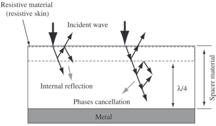
Resonant Absorber Structure (RAS), which attenuates the electro-magnetic radiation in narrow bands16. This absorber consists
basi-cally of a resistive material positioned on a metal plate, with a clear space between the resistive skin and the metal that can be filled by the support of absorbing materials called spacers (Figure 1). For the radiation attenuation to occur in this absorber, the resistive material (resistive skin) must be positioned at one-quarter wavelength (λ/4) of
the incident wave above the metal plate (conductive back skin). This provokes the reflection of a part of the energy of the incident wave and the other part passes through the spacer material and reflects in the metal. In this case, some wave phases are cancelled inside the material and the incident wave is destroyed2,5,17. The advantage of
this type of absorber is the simplicity of all its structure; however, the main disadvantage is the large thickness of the spacer materials, which restricts the application, the application of this material, allied to the high manufacturing cost and low flexibility2,5,17.
The phenomenon of destructive interference can trigger a complex reaction of multiple internal reflections to the material, assisting in the wave-matter interaction and attenuating radiation. When a wave influences a material, a part of the wave energy is reflected and a part is transmitted to the interior of the material. Internally, there are other reflections that promote destruction to each other (geometric cancellation). This phenomenon is similar to what occurs in anti-reflective lenses, which are prepared from layers deposited on a glass surface2.
2. Experimental
In RAM processing nonwoven polymer substrates of PAN and PET were used as support to the radiation absorber center. These substrates are characterized for being formed by the spunlacing of long and discontinued filaments, creating regions rich in emptinesses, thickness of 0.05 and 0.25 cm and area weight of approximately 500 and 400 g.m–2 for PAN and PET, respectively. The polyaniline
electricity conducting polymer was chemically obtained in labora-torial scale, based on the adaptation of the MacDiarmid Method5,18,
from the oxidation of the aniline by the oxidizing agent ammonium peroxydisulfate, in an acid medium (dodecylbenzenesulfonic acid-DBSA), obtaining the conducting polymer PAni-DBSA. For the substrates impregnation’s, mixtures of the conducting polymer were prepared in a polyurethane matrix (PU), available in the market, and a two-component type thermorigid (aliphatic polyesther). The doped polyaniline obtained in the synthesis (as a powder) was added to the polyurethane matrix, in a concentration ratio of 15% (w/w) under mechanical mixing. After the mixtures were prepared (PU-PAni/ DBSA), they were allowed to rest for 60 minutes, in environmental condition, for the complete homogenization of the PU-PAni/DBSA mixture. The application of the mixture in the nonwoven substrates was carried out by the conventional technique of painting, that is, with a brush. The supports were impregnated in one and two faces (surfaces).
2.1. Multilayers structure
From the processed materials the multilayer structures were assembled (“sandwich-type” piling), with substrates of PAN and PET impregnated with the absorber center in one and two faces. The assemblies performed are in Figure 2, and involve the combination of several structures with one and two volumes and the different impregnated faces. The limit of the quantity of volumes (layers) piled was determined by the thickness of the substrates involved in the multilayers formation, in a way that the final thickness of the multilayers structure allowed it to be evaluated with regard to the reflectivity in waveguide.
2.2. Electromagnetic evaluation
The processed materials were evaluated by attenuation of the electromagnetic radiation, via reflectivity measurements by using the waveguide technique, in the microwave frequency band (8to12 GHz). The waveguide was coupled and conjugated with: vector spectrum analyzer and synthesized sweeper generator (45 MHz-26 GHz).
Resistive material (resistive skin)
Spacer material
λ/4 Internal reflection
Phases cancellation
Metal Incident wave
The assembled system is in Figure 3. The samples processed for the electromagnetic evaluation in the frequency band from 8 to 12 GHz have dimensions of 23 x 11 mm, and are fit in a support built with the exact dimensions of the directional coupler (Figure 3). Otherwise, errors may occur in the evaluations of the coefficients of reflection and/or absorption19-21.
For the electromagnetic evaluations of the processed materials, with regard to the efficiency of RAM in the attenuation of the incident radiation, a 2024 aluminum plate of aeronautical application was used. This material is 100% reflecting, generating a curve considered as 0% of absorption of the incident electromagnetic radiation, which is a metal characteristic. In the results processed in the present work, the horizontal line found in the curves, refers to the substrate used, but without impregnation of the absorber center, positioned on the metal plate.
3. Results and Discussion
Figure 4 shows the images obtained through scanning electronic microscopy (SEM) of the substrates of polyacrilonitrile impregnated with the mixture PU-PAni/DBSA. These are representative images of the substrate of PET, because these materials present similar cores and when impregnated they present the same characteristics. It must be emphasized that PU-PAni/DBSA formulations, in concentrations of 10 and 20% (w/w) polyaniline, were also prepared but the results
of the attenuation of the incident radiation were not satisfactory; therefore, they have not been presented in this work.
Figure 4a shows the outer surface of the impregnated substrates and the regions rich with the mixture PU-PAni/DBSA with polyaniline granules dispersed in the polyurethane matrix, which ensures the dispersion of the conducting polymer in the substrate and makes the contact between the two particles possible. When the polyaniline, with its electrical conductivity characteristic, is anchored in a support, it forms electrical conduction paths, which favor the ohmic loss of incident energy22. Figure 4b shows that only the outermost surface of
Structure I 1 face impregnated
in 1 volume
Structure II 2 faces impregnated
in 1 volume
Structure III 1 face impregnated
in 2 volumes
Structure IV 1 face impregnated
in 2 volumes
Structure V 2 faces impregnated
in 2 volumes
Impregnation material Polymer support
Figure 2. Layout of the multilayer structures assembled for electromagnetic evaluation in one or two volumes for the impregnated substrates of PAN and PET.
Sample 23 x 11 mm
0 1 cm Waveguide
(directional coupler) Waveguide (directional coupler)
(a) (b) (c)
Figure 3. Devices used for electromagnetic evaluation: a) sample holder, b) rectangular segment of the waveguide conjugated with the sample holder, and c) all the instruments used in the reflectivity.
30 µm
(a)
100 µm
(b)
the nonwoven gets wet in the impregnation. The analysis of this mi-crography also shows that the use of the PAN substrate and the mixture of PU/PAni promotes a good anchoring of the conducting polymer in the substrate. The layers that were impregnated in the polymeric substrates showed an average thickness of 550 µm (0.55 mm).
Next are shown the evaluations of the reflectivity measure-ments of the material processed in substrates of PAN and PET, Figures 5 and 6, respectively. Correlating the images of SEM with the results obtained from the radiation attenuation, we may say that the largest absorption of incident radiation, shown by some samples, is related to the existence of a larger quantity of conducting particles (agglomerates) in the impregnated substrate, due to the large number of impregnated faces.
Figure 5 shows the reflectivity curves for the impregnated material using the polyacrylonitrile support. In this case, structures I, II and V show significant results in the frequency 9 GHz, attenuating 9 dB, corresponding to 87% of absorption of the incident radiation. In the same frequency, structures III and IV attenuate at an average of 3 to 4 dB, corresponding to 50 and 60% of absorption of the incident radiation, respectively. It is observed in these curves that there are
some variations in the absorption concerning the quantity of material present (more or less deposited layers), and also in relation to the increase of the total thickness of the evaluated material, due to the number of layers used in the assembly of the multilayer structure.
Structures I, II and V shows a better absorption tendency of around 8 GHz and perhaps a possible resonant behavior below this frequency. When the relative curves are compared with these three structures, it is observed that the latter present a similar adjustment and this can be explained by the fact that the structures are similar.
As for structures I and II, although structure II presents a sec-ond impregnated face, these configurations, when positioned on the waveguide, present a similar electromagnetic behavior in relation to the radiation attenuation, because the distance between the first impregnated face and the second face in contact with the aluminum plate is the same. In the case of the green curve (structure II), the performance was relatively better because of the effect of intrinsic absorption of this second layer, but still allows the incident wave to hit the aluminum plate (substrate transparency, that is, the electromag-netic wave passes through the polymeric support). As for structure V, the interface between the two volumes did not contribute to improve the radiation attenuation. The curve of structure IV shows that this arrangement does not favor the attenuation by the λ/4 effect, and the result obtained is probably due to the effect of intrinsic absorption only. In structure III, the arrangement favors the displacement of the maximum of attenuation to higher frequencies, probably due to the
λ/4 effect.
Figure 6 shows the reflectivity curves for the nonwoven sub-strates of PET. The analysis of this figure shows that the behavior of the materials change, which evidences that structures II and III present better results, of around 8 and 9 GHz, and structure I presents larger attenuation for frequencies higher than 11 GHz. These results are attributed to a better interaction of the absorber center with the substrate and, as a consequence, possible larger values of electri-cal conductivity, added to the depth variations in which the wave internally reaches the material. This contribution is evidenced in structure II, which shows a resonance of around 23 dB (~99.7% of absorption) in 9 GHz.
The analysis of the results allows us to conclude that the best proposed structures are I and II, with a tendency of better results for the structure II, and these are not multilayer structures. Therefore, it is concluded that not always the multilayer arrangement is the best proposition in the attenuation of the incident radiation.
The best feature of these dielectrics (multilayer type) processed with the PAN and PET substrates, although there is still a need for optimization with regards to the energy absorption, is their low weight, in other words a low density; because conventional ferrite-based absorbers, processed by the research group of RAM at CTA, and which have absorption values of around 10 dB, have average values of specific mass between 4 and 5 g.cm–3. The results of this work provide
support to understanding the behavior of these materials’ interaction with radiation in the microwave range, in multilayer RAMs, which until then worked with monolayer-type material.
4. Conclusion
The nonwoven PET present the best values of attenuation of the incident radiation. It is suggested that the smaller substrate thickness, allied to a good interaction of this substrate with the formulation of the conducting polymer and to the fact that the reinforcement is characterized by the presence of discontinued filaments disposed at random, may have favored the synergy of the mechanisms of attenu-ation by intrinsic absorption and by multiple reflections inside the
8 9 10 11 12
25 20 15 10 5 0 Absorption (%) 99.7 99.0 97.0 90.0 68.0 0.0 Attenuation (dB) Frequency (GHz) Reference Struture I Structure II Structure III Structure IV Structure V
Figure 5. Electromagnetic reflectivity curves of nonwoven substrates of PAN processed by the PU-PAni/DBSA formulation.
8 9 10 11 12
25 20 15 10 5 0 0.0 90.0 68.0 97.0 99.0 99.7 Absorption (%) Attenuation (dB) Frequence (GHz) Reference Struture I Structure II Structure III Structure IV Structure V
material, which favored larger values of electromagnetic radiation absorption.
The mixture containing 15% (w/w) PAni and polyurethane resin presents good radiation absorption results, with maximum attenua-tion of ~99% for the processed materials. The polyaniline granules involved by the polyurethane matrix provide the formation of con-duction paths, allowing the loss of incident radiation by electrical conduction.
The correlation between the results obtained by scanning elec-tronic microscopy and by reflectivity measuring in waveguide allows to conclude that, in a general way, a good wetting of the substrates occurs by the formulation with polyurethane and, consequently, an adequate anchoring between the PU matrix and the substrate, allowing them to be used as a support for the processing of RAMs with doped polyaniline, to be used in the microwave frequency band.
Acknowledgements
The authors are acknowledge CNPQ for the financial support (Project numbers: 303528/2003-6 and 151929/2005-0) and Comando-Geral de Tecnologia Aeroespacial for the technical support.
References
1. Jenn DC. Radar and Laser Cross Section Engineering. Washington: American Institute of Aeronautics; 1995.
2. Lee SM. International Encyclopedia of Composites. New York: VCH Publishers; 1991.
3. Neri F. Introduction to Electronic Defense Systems. London: Artech House; 2001.
4. Nicolaescu I, Oroian T. Radar Cross Section. In: Proceedings of IEEE;
Telsiks. Yugoslavia: IEEE; 2001:65-68.
5. Folgueras LC. Obtenção e caracterização de materiais absorvedores de microondas flexíveis impregnados com polianilina. [Tese de Doutorado]. São José dos Campos, Brazil: Instituto Tecnológico de Aeronáutica; 2005.
6. Chambost G. STEALTH: Making missiles ‘invisible’. Revue Aerospatiale.
1996; (125):32-36
7. Schleher DC. Electronic Warfare in the Information Age. London: Artech House; 1999
8. Noor AK, Venneri SL, Paul DB, Hopkins MA. Structures technology for future aerospace systems. Computers and Structures. 2000; 74(5):507-519.
9. Stonier RA. Stealth Aircraft and Technology from World War II to the Gulf, Part I: History and background. Society of Aerospace Materials and Process Engineering – SAMPE Journal. 1991; 27(4):9-17.
10. Fauveaux S, Wojkiewicz JL, Miane JL. Broadband electromagnetic shields using polyaniline composites. Electromagnetics. 2003; 23(8):617-627.
11. Roberts J. High frequency applications of ferrites. London: The English Universities Press Ltda.; 1960.
12. Lax B, Button KJ. Microwave ferrites and ferrimagnetics. New York: McGraw-Hill Book Company, Inc.; 1962.
13. Inui T, Koniski K, Oda K. Fabrications of broad-band RF-absorber composed of planar hexagonal ferrites. IEEE Transactions on Magnetics. 1999; 35(5):3148-3150.
14. Olmedo L, Chateau G, Deleuze C, Forveille JL. Microwave characterization and modelization of magnetic granular materials. Journal of Applied Physics. 1993; 73(10):6992-6994.
15. Silva FS, Rezende MC. Estudo, desenvolvimento e caracterização de materiais absorvedores de radiação microondas para uso aeronáutico e de telecomunicações. In: 9 Simpósio Brasileiro de Microondas Optoeletrônica; 2000; João Pessoa, PB.
16. Barton DK, Leonov SA. Radar Technology Encyclopedia. London: Artech House; 1997.
17. Kern DJ, Werner DH. A genetic algorithm approach to the design of ultra-thin electromagnetics bandgap absorbers. Microwave Optical Technology Letters. 2003; 38(1):61-64.
18. MacDiarmid AG, Chiang JC, Richter AF, Somarisi NLD, Epstein AJ. Polyaniline: synthesis and characterization of the emeraldine oxidation state by elemental analysis. In: Alcacer L, (ed.). Conducting Polymers:
Special Applications. Dordrecht: Reidel; 1987.
19. Laverghetta TS. Microwave Measurements and Techniques. Dedham, Massachusetts: Artech House; 1976.
20. Bussey HE. Measurement of RF properties of materials, A survey.
Proceedings of the IEEE. 1967; 55(6):1056-1053.
21. Afsar MN, Birch JR, Clarke RN, Chantry GW. The measurement of the properties of materials. Proceedings of the IEEE. 1986; 74(1):183-199.