E. Marcisz et alii, Frattura ed Integrità Strutturale, 34 (2015) 379-386; DOI: 10.3221/IGF-ESIS.34.42
379
Focussed on Crack Paths
Influence of control parameters on the crack paths in
the aluminum alloy 2024 under bending
E. Marcisz, D. Rozumek, Z. Marciniak
Opole University of Technology, Poland
[email protected], [email protected], [email protected]
ABSTRACT.The paper presents development of crack paths in aluminium alloy 2024. Fatigue tests were carried out for specimens with rectangular cross-section. The specimens were put to bending at controlled energy parameter amplitude and bending moment amplitude. The proposed method of conducting research with the controlled energy parameter has been presented in [1]. The energy parameter model proposed by Macha has been used in the tests. Tests with controlled energy parameter amplitude allow observing crack growth depending on maximum shearing stress surface. Tests with controlled bending moment amplitude allowed observing two types of crack paths.
KEYWORDS. Energy parameter; Bending moment; Crack growth.
INTRODUCTION
n majority, engineering structures, machines and technical devices struggle against material fatigue problem. Literature sources broadly specify the methods for fatigue life assessment and diagnosing the reasons of damage. Material fatigue life is described using fatigue characteristics: stress (a–Nf), strain (a–Nf) and energy (Wa–Nf). Most
frequently, fatigue test results are illustrated by Wöhler fatigue characteristic. Manson–Cofin–Basquin formulas describe material fatigue life using strain characteristics. Specification of stress and strain characteristics is defined in the ASTM standard [2, 3]. Whereas, fatigue characteristics obtained during tests with energy parameter control were proposed in the studies [1, 4]. Observations and analyses of crack path development are carried out in order to obtain additional information concerning changes occurring in a material.
Different fatigue crack paths are observed during tests, depending on material used and loading type. Growth rate of these paths has direct effect on material life.
The aim of the paper is comparison of crack paths in aluminum alloy 2024 for bending tests performed with controlled energy parameter amplitude and bending moment amplitude.
THE MATERIAL AND TEST PROCEDURE
he material tested is aluminium alloy 2024, characterised by low resistance to oxidation, non-weldability and average workability. This material is used to make shafts, screws, pistons, couplings, hydraulic valves and aircraft parts. Tab. 1 shows chemical composition of the material and Tab. 2 specifies static properties of aluminium alloy 2024.
I
E. Marcisz et alii, Frattura ed Integrità Strutturale, 34 (2015) 379-386; DOI: 10.3221/IGF-ESIS.34.42
380
Cu Mn Zn Mg Fe Cr Si Ti Al
4.40 0.62 0.08 1.70 0.25 0.01 0.13 0.05 Balance
Table 1: Chemical composition (in wt %) of the 2024 aluminium alloy
y (MPa) u (MPa) E (GPa) A5 (%)
432 552 77.5 12
Table 2: Mechanical properties of the 2024 aluminium alloy
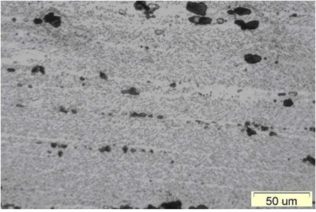
Aluminium alloys containing copper and magnesium, that is duralumin, are among materials characterised by high
strength properties. In the structure of a specimen cut off along the rod axis, are visible elongated grains of the solid
solution as well as numerous precipitations of the intermetallic phase CuAl2,Al3Mg2, Al6Mn containing iron Cu2FeAl
arranged in a streaked way, mainly on the grain boundaries (Fig. 1). Precipitations of these phases significantly influence
on strength and hardness of 2024 aluminium alloy. In particular, the precipitations in the phase boundaries decrease the
plastic properties.
Figure 1:The 2024 aluminium alloy microstructure under magnification 500x
Test pieces are square cross-section specimens taken from a bar 20 mm in diameter, shown in Fig. 2.
Figure 2:Shape and dimensions of specimen (in mm).
E. Marcisz et alii, Frattura ed Integrità Strutturale, 34 (2015) 379-386; DOI: 10.3221/IGF-ESIS.34.42
381 rotation motion of vibrators generate vertical moves of lever which caused loading of specimens. The control and measuring sub-assembly records histories of stresses, strains, energy parameter and hysteresis loops [5].
Figure 3:Fatigue test stand MZGS-100Ph: 1 – specimen, 2 – clamp, 3 – grip, 4 – bending lever, 5 – rod, 6 – vibrator discs, 7 – springs, 8 – flat springs, 9 – machine base, 10 – engine, 11 – toothed belts.
In the closed-loop control system of test stand MZGS-100Ph the amplitude Wa of a new energy parameter for
determination of fatigue characteristic under cyclic bending was used. The history of normal strain energy density parameter W(t) is defined as [6]
0,5
i i iplW t t t (1)
where ipl = (ti) for (ti) = 0 and i = 1, 2, 3,....
In Eq. (1) ipl is the plastic strain registered in the moment ti, when the stress (ti) is equal to zero, and remains constant
to the moment ti+1 when the stress reaches zero again, i.e. (ti+1) = 0. Then the new registered value of plastic strain i+1pl
replaces the previous one ipl. This procedure is repeated for each cycle of bending.
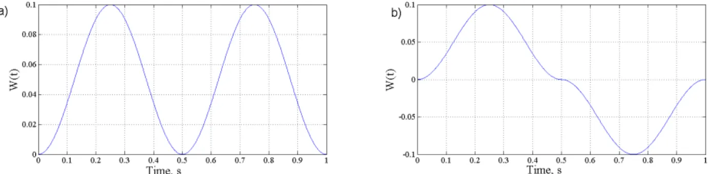
A sample trajectory of energy parameter is shown in Fig. 4. Fig. 4a presents energy parameter course according to the Smith-Watson-Topper relationship [7], and Fig. 4b the course of modified energy parameter. Fig. 4 allows observing that
parameter WaSWT applies to positive values only, while the parameter defined by formula (1) applies both to positive and
negative values.
E. Marcisz et alii, Frattura ed Integrità Strutturale, 34 (2015) 379-386; DOI: 10.3221/IGF-ESIS.34.42
382
TEST RESULTS
he 2024 aluminum alloy specimens were tested under bending with range frequency of 11-14 Hz and a given
amplitude parameter in the range of Wa = 0.2-0.4 MJ/m3. During the tests, histories of stress, strains, energy
parameters and hysteresis loops, (-), were measured and registered. Fatigue test with controlled bending
moment amplitude have been conducted in range a= 187.5 – 255 MPa.
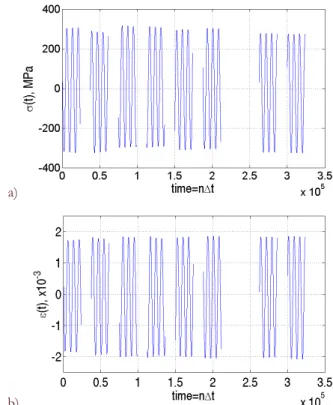
Fig. 5 shows the exemplary history of energy parameter, W(t), and in Fig. 6 the history of stresses, σ(t), and strains, ε(t),
(the first 6 blocks cover from 0 to 64000 cycles, the next 2 blocks represent cycles from 64000 to 166000 cycles). The
example, shown in Fig. 5 concerns the results of the amplitude of the energy parameter Wa = 0.30 MJ/m3, the specimen,
which was failured after Nf = 348100 cycles. Based on the present course of W(t), it can be seen slight fluctuations in the
amplitude Wa, which are the result of periodic (non-continuous) calculations of this amplitude in the control system for
the new values of stresses and strains. Relative error, ∆W, in this example was below10%.
Figure 5: Exemplary history of the energy parameter, W(t), under bending in the function of time, t = nt, n - number of discrete history values, t = 1.298710-5 s - sampling time
a)
b)
Figure 6: An exemplary history: a) - the stress σ(t), b) - strain ε(t) under bending in the function of time, t = nt, n - number of discrete history values, t = 1.298710-5 s - sampling time
E. Marcisz et alii, Frattura ed Integrità Strutturale, 34 (2015) 379-386; DOI: 10.3221/IGF-ESIS.34.42
383 From the diagrams in Fig. 6, it can be observed that the values of stresses and strains in registered histories slightly oscillate around some fixed values. A small decrease of stress can be observed at the initial stage of test (Fig. 6a), whereas strain presents the opposite behaviour (Fig. 6b). Thereafter, both histories stabilize during the test.
Fig. 7 presents 2024 aluminum alloy fatigue characteristics, determined on the base of tests with controlled energy
parameter amplitude Wa at bending. The tests have been performed at four levels Wa = 0.2, 0.3, 0.35, 0.4 MJ/m3.
Figure 7: The fatigue characteristic (Wa-Nf) of 2024 aluminum alloy under bending with a controlled amplitude of the energy
parameter.
Fig. 8 presents 2024 aluminum alloy fatigue characteristics, determined with controlled amplitude of the bending moment
a at bending. In the range of finite lifetime, the tests have been executed at five levels a = 187.5, 200, 232, 233, 255
MPa. At least two specimens were tested at each of stress levels.
Figure 8: The fatigue characteristic (a-Nf) of 2024 aluminum alloy with controlled amplitude of the bending moment
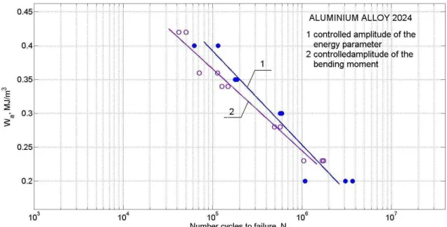
Fig. 9 presents fatigue characteristic of 2024 aluminum alloy with controlled amplitude of the bending moment a and
E. Marcisz et alii, Frattura ed Integrità Strutturale, 34 (2015) 379-386; DOI: 10.3221/IGF-ESIS.34.42
384
187.5, 232, 233, 255 MPa, values of elastic energy have been calculated according to linear-elastic model of solid(Wa =
a2/2E), obtaining Wa = 0.23, 0.28, 0.34, 0.36, 0.42 MJ/m3.
Figure 9:The fatigue characteristic of 2024 aluminum alloy under bending with a controlled amplitude of the 1 – energy parameter with Eq. (1), 2 – energy parameter with linear-elastic model of solid.
The results of fatigue tests have been subjected to statistical analysis, and calculated according to relations (2) and (3), coefficients of regression equation and correlation are shown in Tab. 3.
logNf A m Wa (2)
logNf A m a (3)
where:
Wa - amplitude of energy parameter,
a - amplitude of nominal stress,
Nf - number of cycles to failure,
A i m - coefficients of the regression equation
Material A B r Type of research
2024 7.030 -7.216 0.960
Controlled energy parameter amplitude - Eq. (2)
2024 10.293 -0.022 0.981
Controlled bending moment amplitude - Eq. (3)
Table 3: Coefficients of the regression equation and correlation at a significance level, = 0.05 with a controlled amplitude of the nominal stress.
Cracks of specimens from aluminium with phase structure occur in the slip plane {111} under shear stress, which are
almost independent of grains space orientation. In the specimen (Fig. 10) it is observed the main, zigzag crack developed
through transcrystallic phase grains. This crack is changing direction on grain boundaries. It can also be noticed some
E. Marcisz et alii, Frattura ed Integrità Strutturale, 34 (2015) 379-386; DOI: 10.3221/IGF-ESIS.34.42
385 Figure 10:Fatigue crack path of the aluminium alloy 2024.
A sample development of crack paths at controlled energy parameter is shown in Fig. 11. Fig. 11a presents crack path
observed at energy parameter Wa = 0.4 MJ/m3; the specimen was damaged after 11550 cycles. Fig. 11b shows crack path
for a specimen examined at energy parameter value Wa = 0.35 MJ/m3; the specimen was damaged after 88900 cycles. A
sample development of crack paths under bending moment control is illustrated in Fig. 12. Crack path in Fig. 12a was
observed at stress value a = 255 MPa, which according to linear-elastic model corresponds to energy parameter Wa =
0.42 MJ/m3; the specimen was damaged after 50300 cycles. Fig. 12b shows crack path obtained during tests for stress a
= 233 MPa. According to linear-elastic model, it corresponds to energy parameter Wa = 0.36 MJ/m3. The specimen was
damaged after 70800 cycles. Presented photos allow observing that crack paths in Figs. 11a and 12a develop in much the same way. Greatest changes in crack path development directions (zigzag) were observed during tests at controlled
bending moment amplitude a = 233 MPa (Fig. 12.b). In case of controlled energy parameter and bending moment the
specimens had different cracking courses. After initiation, cracks develop along different planes, where the plane of highest shearing stress is prevailing.
a b
Figure 11:Fatigue crack path for controlled amplitude of the energy parameter
a b
E. Marcisz et alii, Frattura ed Integrità Strutturale, 34 (2015) 379-386; DOI: 10.3221/IGF-ESIS.34.42
386
CONCLUSIONS
he following conclusions were formulated on the basis of alloy 2024 tests carried out with controlled energy parameter amplitude and bending moment amplitude:
1. Life of specimens at controlled energy parameter is slightly better than life of specimens at controlled bending
moment amplitude.
2. The characteristics show converging tendency at lower values of the parameters, which is the effect of strains being
taken into consideration (or not).
3. Depending on applied load and parameter, fatigue crack paths had different courses.
REFERENCES
[1] Marcisz, E., Marciniak, Z., Rozumek, D., Macha E., Fatigue characteristics of aluminium alloy 2024 under cyclic
bending with the controlled energy parameter. Key Engineering Materials, 592-593 (2014) 684-687.
[2] ASTM E 606-80. Standard practcite for: Statistical analysis of linearized stress- life (S-N) and strain-life (-N) fatigue
data [in:] Annual Book of ASTM Standards, 03.01 Philadelphia (1989) 601-611.
[3] ASTM E 739-80. Standard practcite for: Statistical analysis of linearized stress- life (S-N) and strain-life (-N) fatigue
data [in:] Annual Book of ASTM Standards, 03.01 Philadelphia (1989) 667-673.
[4] Marcisz, E., Marciniak, Z., Rozumek, D., Macha, E., Energy fatigue characteristic of C45 steel subjected to cyclic
bending, Key Engineering Materials, 298 (2014) 147-152.
[5] Achtelik, H., Marciniak, Z., Macha, E., Marcisz, E., Rozumek, D., The stand for fatigue tests of materials with the
controlled energy parameter under bending and torsion, Przegląd Mechaniczny, Warszawa, 12 (2013) 34-38, in Polish.
[6] Macha, E., Słowik, J., Pawliczek, R., Energy based characterization of fatigue behavior of cyclically unstable materials,
Solid State Phenomena, 147-149 (2009) 512-517.
[7] Smith, K., Watson, P., Topper, T., A stress-strain function for the fatigue of metals, J. Materials, 5 (1970) 767-779.