*e-mail: [email protected]
Comparative Investigation of the Adhesion of Ce Conversion Layers and Silane
Layers to a AA 2024-T3 Substrate Through Mechanical and Electrochemical Tests
Luis Enrique Morales Palominoa, Zoltán Pásztib, Idalina Vieira Aokia, Hercílio Gomes de Meloa*
a
Escola Politécnica da USP, Departamento de Engenharia Química,
Av. Prof. Luciano Gualberto, Trav. 3, n. 380,
Cidade Universitária, 05508-900 São Paulo - SP, Brazil
b
Institute of Surface Chemistry and Catalysis, Chemical Research Center,
Hungarian Academy of Sciences, 59-67 Pusztaszeri út, Budapest, Hungary, H-1025
Received: March 22, 2007; Revised: November 8, 2007
Cerium conversion layers and silane films are among the potential substitutes for the carcinogenic chromate conversion layers used to protect high-strength Al alloys. In the present work the adhesion of a cerium conversion layer and of a silane film to an aluminium alloy (AA) 2024-T3 substrate was investigated using mechanical and electrochemical tests. Scanning electron microscopy (SEM)- X ray energy dispersive spectroscopy (EDS), Fourier transform infrared spectroscopy (FT-IR) and X ray photoelectron spectroscopy (XPS) were used to characterize the layers prior and after the mechanical test consisting of ultrasonic rinse in deionized water during 30 minutes. Mechanically tested and untested layers were also submitted to electrochemical impedance spectroscopy (EIS) and anodic polarization measurements in 0.1 M NaCl solution. The results of the characterization tests have pointed to a stronger adhesion of the Ce layer to the substrate in comparison with the silane film, which was confirmed by the electrochemical tests. The adhesion between the silane film and the Ce conversion layer was also tested, to evaluate the possibility of using the system as a protective bi-layer in accordance with the new trends being developed to substitute chromate conversion layers.
Keywords: adhesion, AA 2024-T3, SEM-EDS, EIS, silane, cerium, FTIR, XPS
1. Introduction
AA 2024-T3 is largely used in aerospace applications. In this alloy, heterogeneous microstructure is intentionally developed to optimise mechanical properties. Unfortunately, the complex micro-structure makes it susceptible to localized corrosion during service and complicates aqueous surface finishing processes1-3.
It is widely known that 2xxx series alloys are among the most corrosion prone commercial materials in common use. The inhomo-geneous distribution of Cu in these alloys microstructure has been shown to be a major cause for their low resistance to pitting and stress corrosion cracking. Specifically, the concentration of Cu in second-phase particles and the local depletion of Cu in certain microstructural regions establish local galvanic cell resulting in localized attack1,2. Due to this fact, for commercial use, their corrosion resistance is improved by a complete coating system consisting of three individual layers: a conversion layer (pre-treatment), a primer and a topcoat4. In this system the substrate pre-treatment plays an important role on the corrosion resistance as it promotes adhesion with the primer and also imparts some corrosion protection5-7.
For many decades, chromate conversion coatings have been reported as the most efficient pre-treatment used as anti-corrosive inhibitors and adhesion promoters to the surface of AA employed in the aircraft industry4,8-12. The use of chromates is, however, be-ing restricted worldwide, as they are considered highly toxic and carcinogenic13-20. Because current environmental legislation is mov-ing towards total exclusion of Cr6+ of industrial processes, and due to tightening of regulatory pressures in order to reduce the hazardous waste of chromium, many attempts are being made to develop non-toxic alternative methods for corrosion protection of these materials. One of these non-toxic substitute treatments is based on the use of rare earth salts, in particular those of cerium13,17-21.
Based initially on immersion treatments employing cerium salts as corrosion inhibitors, eg. CeCl3, Ce ions have shown promising behavior as corrosion inhibitors for AA17,18. Later, using conversion baths, Ce ions in solution were reported to form stable hydroxides/ oxides films on the metal surface at locations of increased pH due to local cathodic activity13,19-21. The deposition of Ce(OH)
3 and/or CeO2 gives the films a distinctive yellow colour. Such chemical passivation process produces coatings that are more corrosion resistant than the naturally formed oxide film on the surface of AA19,20,22,23, mainly due to polarization of the cathodic reaction. However, these films have been reported to have an inhomogeneous thickness24. Recently the introduction of a pre-treatment step that provoked the deposition of a Cu-rich smut on the alloy surface seems to have overcome this latter drawback22,23.
con-concentration, hydrolysis time, and solution pH .
The aim of this study is to indirectly evaluate the bond strength of Ce conversion layers and silane layers to a AA 2024-T3 substrate. With this purpose samples coated with each one of the layers were characterized using SEM/EDS, FTIR and XPS prior and after be-ing submitted to an adherence test consistbe-ing of immersion durbe-ing 30 minutes in an ultrasonic bath5,6. The use of such methodology in replacement of the traditionally used ASTM 3359-0233 seemed to us more adequate as it equally test the coating adhesion all over the surface; however, for the sake of comparison, this test was also performed. Moreover the corrosion properties of samples submitted to the mechanical tests or not were assessed through EIS experiments and anodic polarization curves in 0.1 M NaCl solution.
As recent researches aiming to substitute chromate conversion layers are moving towards layers with more complex structure29,30, 34-36, in order to evaluate the affinity between Ce and silane layers, the same tests were performed with samples coated with a Ce-silane bi-layer.
2. Experimental Procedure
The AA 2024-T3 used in this work was supplied by a Brazilian industry (EMBRAER) as sheets with dimensions of (100 x 100 x 0.1) cm. This alloy has a high Cu content, typically between 3.8-4.9% (wt. (%))37. The pre-treatment procedure used to prepare the samples for deposition of the Ce conversion layer has been described elsewhere as well as the conversion bath composition23.
To obtain the silane coating the samples were prepared in the same manner as that used to produce the Ce conversion layer23 with the difference that the Cu-rich smut left at the sample surface after immersion in the acetic acid solution was removed by vigorously washing.
The silane solution was prepared by adding 4% (w.w–1) of BTSE (bis-1, 2-(triethoxysilyl) ethane) molecules to a 50%/50% (w.w–1) ethanol/water solution, which, afterwards, had its pH adjusted to a value between 3.5 and 4 by the addition of acetic acid, and was left to hydrolyse during 30 minutes, according to the procedure described by Oliveira38. It must be emphasized that the silane solution used in the present work was designed specifically to avoid the use of the carcinogenic methanol. To obtain the silane coatings, the pre-treated samples were immersed for 5 minutes in the hydrolysed solution at 25 °C. Next, the samples were left at rest for 2 minutes at room temperature and subsequently cured at 100 °C for 10 minutes which can be considered as a mild curing condition. The same procedure was adopted to obtain the top silane layer in the bi-layer coating, with the difference that the samples had been previously coated with the Ce conversion coating.
All the electrochemical tests were performed using a classical three electrodes cell with Ag/AgCl(sat.) and a platinum grid as reference and counter electrode, respectively, which were always positioned at the same place relatively to the working electrode (WE). Cell construction details can be found elsewhere22,23. The experiments were performed in aerated conditions and at room temperature.
The set-up used to control the impedance experiments was com-posed of a Solartron 1260 frequency response analyzer (FRA) coupled to a Solartron 1287 electrochemical interface, the experiments were controlled by the software Corrware®. The diagrams were obtained
was initiated after the completion of the impedance measurements, i.e. after 72 hours of contact of the different samples with the test electro-lyte, and finished when the total anodic current reached 1 mA.
SEM/EDS analyses were performed in all the coated samples and in the bare alloy. The equipment used was a Philips XL – 30 scanning microscope equipped with an EDS spectrometer. The acceleration voltage used to carry out the analyses was 20 keV, giving a penetration depth of approximately 1 µm. Semi-quantitative elemental analysis was executed using internal standards of the equipment. The mechani-cal adhesion test consisted in immersing the coated sample during 30 minutes in DI water containing ultrasonic bath.
The FT-IR technique is well known as a powerful tool in the field of polymer surface characterization. FT-IR measurements were conducted on a Bomem MB 100 spectrophotometer in the mid-IR range from 4000 to 400 cm–1. All IR spectra were obtained at an incident angle of 75° normal to the surfaces of specimens, with a spectral resolution of 4 cm–1.
XPS measurements were carried out using an electron spec-trometer manufactured by OMICRON Nanotechnology GmbH (Germany). The photoelectrons were excited by AlKα (1486.6 eV) radiation. Spectra were recorded at normal emission in the Constant Analyser Energy mode.
3. Results and Discussion
3.1. SEM characterization
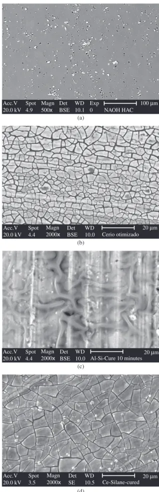
Figure 1 presents micrographs of the bare sample, Figure 1a, and of the AA 2024-T3 alloy coated with the different treatments: Ce conversion layer (Figure 1b), silane film (Figure 1c) and bi-layer Ce-silane (Figure 1d). These images have already been discussed elsewhere39, however their main aspects will be highlighted. The bare sample presents coarse Al-Cu-Mg and Al-Cu-Fe-Mn intermetallics distributed on its whole surface, while, the Ce coated sample presents its usual dry-mud appearance. The presence of the silane layer on the sample surface is evident in Figure 1c, however it has been demonstrated that silanes does not adhere uniformly on Al surface5,6 the same was verified in the present work. In its turn, comparison of Figures 1b and 1d shows that the curing of the silane layer seems to introduce compressive stress (the cracks are longer and narrower) in the Ce conversion layer.
The micrographs of the coated samples after the mechanical test are presented in Figure 2. From the images is possible to observe that the coatings have been removed from the sample surface at different de-grees. For the sample protected with the Ce-conversion layer (Figure 2a) large amounts of the coating has been removed. On the other hand, the detachment of the silane layer can be inferred due to the presence of the intermetallics (Figure 2b). For the last micrograph presented in this series (Figure 2c) it can be observed that the mechanical test removes only small amounts of the protective layer. This seems to indicate a synergetic action between the Ce and silane layers, in accordance with what had already been shown with the untested samples.
Vol. 10, No. 4, 2007 to a AA 2024-T3 Substrate Through Mechanical and Electrochemical Tests 401
Figure 1. SEM micrographs of the AA 2024-T3 alloy. a) Bare (after the standard pre-treatment); b) Cerium coated; c) Silane coated; and d) Cerium-silane coated (cured).
Acc.V 20.0 kV
Spot 3.7
Magn 2000x
Det SE
WD
10.0 Al-Ce ultrasom 20 µm
(a)
Acc.V 20.0 kV
Spot 4.5
Magn 2000x
Det BSE
WD 9.9
20 µm
Al-Si-sem Cu-Cured-com Ultra-som
(b)
Acc.V 20.0 kV
Spot 4.9
Magn 2000x
Det SE
WD 9.9
20 µm Al-Ce-Silano-Cured-Ultrasom
(c) Acc.V
20.0 kV Spot 4.9
Magn 500x
Det BSE
WD 10.1
Exp 0
100 µm NAOH HAC (a)
Acc.V 20.0 kV
Spot 4.4
Magn 2000x
Det BSE
WD 10.0
20 µm Cerio otimizado (b)
Acc.V 20.0 kV
Spot 4.4
Magn 2000x
Det BSE
WD 10.0
20 µm Al-Si-Cure 10 minutes (c)
Acc.V 20.0 kV
Spot 3.5
Magn 2000x
Det SE
WD 10.5
20 µm Ce-Silane-cured
(d)
Figure 2. SEM micrographs of the AA 2024-T3 alloy after the ultrasonic bath. a) Cerium coated; b) Silane coated; and c) Cerium-silane coated (cured).
is stronger indicating a better interaction between the silane coating and the Ce conversion layer than with the Al substrate. On the other hand, the intensity of the peaks associated with Ce barely changes prior and after the mechanical tests indicating an excellent adhesion of the conversion layer to the metallic substrate.
3.2. FTIR characterization
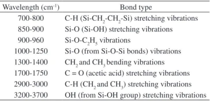
Figure 4 shows the FTIR spectra of the BTSE silane film on samples submitted to the different treatments. The assignments of the characteristic absorption bands are given in Table 17,31,40. The bands in the SiOSi region, between 1000 to 1250 cm–1, are clearly more intense in the bi-layer coated samples. According to the literature40 the band at 1030 cm–1 is indicative of the formation of a long siloxane chain. The higher absorption intensity of this band for the Ce-silane coated sample suggests longer siloxane chains for this particular sample. On the other hand, the absorption intensities of the bands corresponding to silanol (SiOH) at, 3363, 3243 and 870 cm–1 are nearly the same for all the samples, indicating the existence of practically the same amount of non condensed silanol groups in all the samples. Finally, the bands belonging to the C-H stretching (CH2 and CH3) group: at 2972, 2924, and 2848 cm–1 are also more intense in the Ce-silane coated sample indicating a higher organization degree of the chains. Comparing the spectra obtained for the sonicated samples, (B) and (D), all the adsorption bands are more intense for the Ce-silane coated sample confirming the stronger adhesion of the silane layer to the Ce conversion coating, as already indicated in the EDS results.
3.3. XPS results
Survey XPS spectra taken for the silane coated AA samples with or without the Ce conversion layer confirmed the presence of C, Si, O, Al, Cu, Mg and – when appropriate – Ce. The amount of other contaminants was typically below the detection limit.
Figure 5 shows the Si and Al XPS spectra of the silane coated samples with or without the Ce conversion layer after curing, elec-trochemical and mechanical testing. All spectra were collected after small amount of ion bombardment, which does not seriously affect
Table 1. Absorption region and bond type found in silane films.
Wavelength (cm-1) Bond type
700-800 C-H (Si-CH2-CH2-Si) stretching vibrations 850-900 Si-O (Si-OH) stretching vibrations 900-960 Si-O-C2H5 vibrations
1000-1250 Si-O (from Si-O-Si bonds) vibrations 1300-1400 CH2 and CH3 bending vibrations 1700-1750 C = O (acetic acid) stretching vibrations 2900-3000 C-H (CH2 and CH3) stretching vibrations 3200-3700 OH (from Si-OH group) stretching vibrations Figure 3. Si (A) and Ce (B) peaks intensity in EDS spectra of single- or bi-layer coated AA 2024-T3 samples prior and after the adhesion test: curve (A) Al-Si; curve (B) Al-Si – sonicated; curve (C) Al-Ce-Si; curve (D) Al-Ce-Si – sonicated; curve (E) Al-Ce; curve (F) Al-Ce – sonicated.
160 200
cps
Energy (keV)
500 550
Ce Ce
cps
Energy (keV)
(a) (b)
4000 3500 3000 2500 2000 1500 1000 500
Counts
(d) (c) (b) (a)
Wavenumber (cm–1)
Vol. 10, No. 4, 2007 to a AA 2024-T3 Substrate Through Mechanical and Electrochemical Tests 403
40 60 80 100 120 140 160 180 200
Intensity (arbitrary unit)
1
2
3
Si 2p Si 2s
Al 2p Al 2s
1 --- Cured 2 --- Electrochemical test 3 --- Mechanical test
Binding energy (eV) Al-silane
5p 4 keV 18
(a) (b)
40 60 80 100 120 140 160 180 200
Intensity (arbitrary unit)
1
2
3
Si 2p
Si 2s
Al 2p Al 2s
Binding energy (eV)
1 --- cured 2 --- electrochemical test 3 --- mechanical test
Al-Ce Ox-Silane 5p e keV 18
Figure 5. XPS analysis showing Al 2s and Si 2p signals from an AA 2024-T3 coated with Al-Si a), Al-Ce-Si b), before and after mechanical and electrochemi-cal test.
6 mHz
6 mHz
6 mHz
0 30000 60000 90000 120000
–125000
–95000
–65000
–35000
–5000
Z' (Ohm.cm–²)
Z'' (Ohm.cm
–²)
Al-Ce Al-Si Al-Ce-Si
(a) (b)
6 mHz 6 mHz
6 mHz
0 25000 50000 75000 100000 125000
–125000
–100000
–75000
–50000
–25000
0
Z' (Oh.cm–²)
Z'' (Ohm.cm
–²)
Al-Ce Al-Si Al-Ce-Si
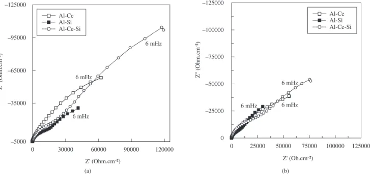
Figure 6. Impedance response in 0.1 M NaCl solution for AA 2024-T3 alloy with different treatments, a) before b) after ultrasonic bath. Immersion time 72 hours.
the layer structure, but more or less removes the adventitious hydro-carbon contamination. The analysis of the figure shows that, in all cases, there is a measurable Al signal, most noticeable around 75 eV binding energy. This indicates that the coverage of the substrates by the different layers is never perfect. While the intensity of this signal is relatively weak for the cured (non-tested) and mechani-cally tested samples, the electrochemical test always significantly reduces the coverage, as indicated by the stronger intensity of the peak. Assuming that the silane layer thickness is much larger than
the information depth of the XPS and the Ce conversion layer is completely covered by the silane, the coverage of the substrate by the silane layer was calculated to be around 95-99% in the cases of the cured and mechanically treated samples, while for the electro-chemical tested ones the values were around 75-80%.
3.4. EIS results
the silane coating, once the low frequency impedance value is higher than the sum of the individual contributions. Moreover, the results also evidences the excellent adhesion of the Ce-conversion layer to the Al substrate, since, proportionally, the decrease in the real impedance value after the mechanical test was lower for this particular sample.
3.5. Anodic polarization behavior
The anodic polarization curves for the different samples, without and with the mechanical test, after 72 hours of immersion in the test electrolyte are presented in Figure 7a and b, respectively. The curves were obtained immediately after the completion of the impedance tests depicted in Figure 6. Comparing the response of samples with the same coating, a clear displacement of the currents to higher values was observed after the sonication test; however, the sample coated only with the silane layer suffered the stronger modification as the passive region almost disappeared after the mechanical test. Once more the bi-layer (Ce-silane) coated sample exhibited the best behavior.
3.6. Adhesion test according to ASTM D 3359-02
33To confirm the good adhesion properties of the Ce conversion layer to the Al substrate, samples coated with only with the Ce
4. Conclusions
In this work a comparative investigation of the adhesion of Ce conversion layers and silane layers to a AA 2024-T3 substrate through mechanical and electrochemical tests was performed. The results of the analytical techniques (FT-IR, EDS and XPS) evidenced that silane molecules have equivalent affinity to the Al substrate and to the Ce conversion layer. Moreover, SEM-EDS observations in sam-ples previously submitted to ultrasonic bath testing put in evidence an excellent adhesion of the Ce layer to the surface of the alloy. This was improved in the sample coated with the bi-layer Ce-silane, evidencing a synergistic effect of the Ce conversion layer and the silane coating.
The performance analysis through EIS and anodic polarization curves indicated superiority of the bi-layer, before ultrasonic bath, in comparison with samples protected by only a monolayer of ce-rium or silane. Additionally, after the application of the mechanical test the impedance values were still higher than the samples coated with only a monolayer not submitted to any type of mechanical test, ratifying the observations of good adhesion properties of the bi-layer to the substrate.
In addition, the results of FT-IR showed a slightly increase of the formation of siloxane structures (Si-O-Si) for the sample with bi-layer (Ce-silane) before ultrasonic bath, which may play a critical role in the corrosion protection process, as evidenced in the results of the electrochemical tests.
Acknowledgments
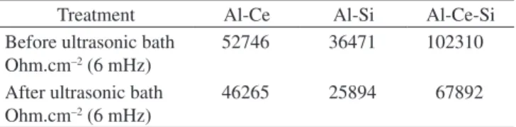
The author Hercílio Gomes de Melo is thankful to FAPESP, São Paulo state (Brazil) research financing agency for the financial sup-Table 2. Real impedance at 6 mHz for AA 2024-T3 coated according to
the different procedures prior and after the sonication test. Immersion time 72 hours.
Treatment Al-Ce Al-Si Al-Ce-Si
Before ultrasonic bath Ohm.cm–2 (6 mHz)
52746 36471 102310
After ultrasonic bath Ohm.cm–2 (6 mHz)
46265 25894 67892
10–8 10–7 10–6 10–5 10–4 10–3
–0.7 –0.6 –0.5 –0.4
I (Amps.cm–2)
E (V
olts)(Ag/AgCl)
Al-Ce Al-Si Al-Ce-Si
(a) (b)
–0.7 –0.6 –0.5 –0.4
I (Amps.cm–2)
E (V
olts)(Ag/AgCl)
Al-Ce Al-Si Al-Ce-Si
10–7 10–6 10–5 10–4 10–3
Vol. 10, No. 4, 2007 to a AA 2024-T3 Substrate Through Mechanical and Electrochemical Tests 405
Figure 8. Sequence of the adhesion test on surface AA 2024-T3, with Ce-conversion layer (a1, b1) and bi-layer Ce-silane (a2, b2). Images obtained with digital camera.
(a1) (a2)
(b1) (b2)
port and Luis E.M. Palomino is thankful to CNPq, Brazilian research financing agency for the grant.
References
1. Buchheit RG, Grant RP, Hlava PF, Mckenzie B, Zender GL. Local
dis-solution phenomena associated with S phase (Al2CuMg) particles in
aluminum alloy 2024-T3. Journal of the Electrochemical Society. 2002;
144(8):2621-2628.
2. Guillaumin CH, Mankowski G. Localized corrosion of 2024 T351
alumin-ium alloy in chloride media. Corrosion Science. 1998; 41(3):421-438.
3. Blanc C, Gastaud S, Mankowski G.Mechanistic Studies of the Corrosion
of 2024 Aluminum Alloy in Nitrate Solutions. Journal of the
Electro-chemical Society. 2003; 150:B396-B404.
4. Palanivel V, Huang Y, van Ooij WJ. Effects of addition of corrosion inhibitors to silane films on the performance of AA2024-T3 in a 0.5M
NaCl solution. Progress in Organic Coatings. 2005; 53(2):153-168.
5. Teo M, Kim J, Wong PC, Wong KC, Mitchell KAR. Pre-treatments ap-plied to oxidized aluminum surfaces to modify the interfacial bonding with bis-1,2-(triethoxysilyl)ethane (BTSE): Part I. High-purity Al with
native oxide. Applied Surface Science. 2005; 252(5):1293-1304.
6. Teo M, Kim J, Wong PC, Wong KC, Mitchell KAR. Pre-treatments ap-plied to oxidized aluminum surfaces to modify the interfacial bonding with bis-1,2-(triethoxysilyl)ethane (BTSE): Part II. Anodized 7075-T6
Al alloy. Applied Surface Science. 2005; 252(5):1305-1312.
7. Franquet A. Pen CL, Terryn H, Vereecken J. Effect of bath concentration and curing time on the structure of non-functional thin organosilane layers
11. Campestrini P, Westing V, Wit JH. Influence of surface preparation on performance of chromate conversion coatings on Alclad 2024
alu-minium alloy Part II: EIS investigation. Electrochimica Acta. 2001;
46(17):2631-2647.
12. Akiyama E, Markworth AJ, Mccoy JK, Frankel GS, Xia L, Mccreery RL. Storage and release of soluble hexavalent chromium from chromate
conversion coating on al alloys. Journal of the Electrochemical Society.
2003; 150(2):83-91.
13. Aldykewicz AJ, Davenport AJ, Isaacs HS. The investigation of cerium
as a cathodic inhibitor for aluminum-copper alloys. Journal of the
Elec-trochemical Society. 1995; 142:3342-3350.
14. Domingues L, Oliveira C, Fernandes J, Ferreira M, Fonseca I. Corrosion behaviour of environmentally friendly treatments for aluminium alloys. Advanced Materials Forum I.2002; 230(2):392-395.
15. Lewington TA, Alexander MR, Thompson GE, Mcalpine E. Characteri-sation of alkyl phosphonic acid monolayers self assembled on hydrated
surface of aluminium. Surface Engineering. 2002; 18(3):228-232.
16. Subramanian V, Van Ooij WJ. Silane based metal pretreatments as
alternatives to chromating: Shortlisted.Surface Engineering. 1999;
15(2):168-172.
17. Hinton BRW, Arnot DR, Ryan NE. The inhibition of aluminium alloy
corrosion by cerous cations. Metals Forum. 1984; 7(4):211-217.
18. Hinton BRW, Arnot DR, Ryan NE. Cerium conversion coatings for the
corrosion protection of aluminium. Metals Forum. 1986; 9(3):162-73.
19. Xingwen Y, Chunan C, Zhiming Y, Derui Z, Zhongda Y. Study of double
layer rare earth metal conversion coating on aluminum alloy LY12.
Cor-rosion Science. 2001; 43(7):1283-1294.
20. Xingwen Y, Chunan C, Zhiming Y, Derui Z, Zhongda Y. Corrosion be-havior of rare earth metal (REM) conversion coatings on aluminum alloy
LY12. Materials Science and Engineering A. 2003; 284(10):56-63.
21. Campestrini P, Terryn H, Hovestad A, Wit JHW. Formation of a cerium-based conversion coating on AA2024: relationship with the
microstruc-ture. Surface and Coatings Technology. 2004; 176(3):365-381.
22. Palomino LEM, de Castro JF, Aoki IV, de Melo HG. Microstructural and electrochemical characterization of environmentally friendly conversion
layers on aluminium alloys. Journal of the Brazilian Chemical Society.
2003; 14(4):651-659.
23. Palomino LEM, Aoki IV, de Melo HG. Microstructural and electro-chemical characterization of Ce conversion layers formed on Al
al-loy 2024-T3 covered with Cu-rich smut. Electrochimica Acta. 2006;
51(26):5943-5953.
24. Hughes AE, Taylor RJ, Hinton BRW, Wilson L. XPS and SEM
charac-terization of hydrated cerium oxide conversion coatings. Surface and
InterfaceAnalysis. 1995; 23(7-8):540-550.
[triethoxysilylpropyl]tetrasulphide pre-treated AA2024-T3. Corrosion
Science. 2005; 47(3):869-881.
28. Zhu, D, van Ooij WJ. Enhanced corrosion resistance of AA 2024-T3 and hot-dip galvanized steel using a mixture of bis- triethoxysilylpropyl]
tetrasulfide and bis- trimethoxysilylpropyl]amine. Electrochimica Acta.
2004; 49(7):1113-1125.
29. van Ooij, WJ, Zhu D. Electrochemical impedance spectroscopy of bis-
triethoxysilypropyl]tretasulfide on Al 2024-T3 substrates. Corrosion.
2001; 57(5):413-427.
30. Zhu D, van Ooij, WJ. Corrosion protection of AA 2024-T3 by bis-[3-(triethoxysilyl)propyl]tetrasulfide in sodium chloride solution.:
Part 2: mechanism for corrosion protection. Corrosion Science. 2003;
45(10):2177-2197.
31. Franquet A, Terryn H, Vereecken J. IRSE study on effect of thermal curing on the chemistry and thickness of organosilane films coated on
aluminium. Applied Surface Science. 2003; 211(1-4):259-269.
32. Susac D, Sun X, Mitchell KAR. Adsorption of BTSE and γ-APS
orga-nosilanes on different microstructural regions of 2024-T3 aluminum alloy. Applied SurfaceScience. 2003; 207(1-4):40-50.
33. American Society for Testing and Materials. ASTM D 3359-02. Standard
test methods for measuring adhesion by tape test; 1987.
34. Kowayashi Y, Fujiwara Y. Corrosion protection of cerium conversion coat-ing modified with a self-assembled layer of phosphoric acid mono-n-alkyl
ester. Electrochemical and Solid-State Letters. 2006; 9(3):B15-B18.
35. Montemor MF, Cabral AM, Zheludkevich ML, Ferreira MGS. The corro-sion resistance of hot dip galvanized steel pretreated with Bis-functional
silanes modified with microsilica. Surface and Coatings Technology.
2006; 200(9):2875-2885.
36. Ferreira MGS, Duarte RG, Montemor MF, Simões AMP. Silanes and rare earth salts as chromate replacers for pre-treatments on galvanised steel. Electrochimica Acta. 2004; 49(17-18):2927-2935.
37. ALCOA. Alcoa Inc. Pittsburgh 2005 [cited 2006 Aug 20] Available from: www.alcoa.com/aerospace/em/product.
38. Oliveira, F. M. Estudo da influência de organo-silanos na resistência
à corrosão de aço-carbono por meio de técnicas eletroquímicas. [PhD thesis]. São Paulo University: São Paulo; 2006.
39. Palomino LEM, Pacifico IA, Aoki IV, de Melo HG. EIS investigation
of the behaviour of double layer Cerium - Silane pre-treatment on Al 2024-T3 in 0.1M NaCl. In: The European Corrosion Congress; 2005. Proceedings. SPM/ EFC, Lisboa 2005. p. 411.
40. Zhu, D. Corrosion protection of metals by silane surface treatment. [PhD