FLUID DYNAMIC EFFICIENCY OF A HIGH PERFORMANCE
MULTI-VALVE INTERNAL COMBUSTION ENGINE DURING
THE INTAKE PHASE
Influence of Valve-Valve Interference Phenomena
byAngelo ALGIERI
Mechanics Department, University of Calabria, Arcavacata di Rende (CS), Italy
Original scientific paper DOI: 10.2298/TSCI120730221A
The purpose of the present work is the analysis of the fluid dynamic behaviour of a high performance internal combustion engine during the intake phase. In particu-lar, a four-valve spark-ignition engine has been characterised at the steady flow rig. Dimensionless discharge coefficients have been used to define the global fluid dynamic efficiency of the intake system, while the laser-Doppler anemometry tech-nique has been employed to evaluate the mean flow in the valve curtain area and to characterise the interference phenomena between the two intake valves.
The investigation has shown the significant influence of the valve lift on the volu-metric efficiency of the intake apparatus. Moreover, the experimental analysis has highlighted that the valve-valve interference phenomena have a relevant impact on the head breathability, on the flow development within the combustion chamber and on the velocity standard deviations.
Key words: internal combustion engines, intake phase, flow coefficients, laser--Doppler anemometry, valve deactivation, interference phenomena
Introduction
Nowadays, the detailed characterisation of the fluid dynamic behaviour of internal combustion engines represents an essential step to developing and optimising modern internal combustion engines (ICE) [1-5]. A profound knowledge of the intake process, in fact, is neces-sary both when the purpose is to meet the more and more stringent regulations on the exhaust gas emissions and when the goal is to increase the performances of race engines [1, 6-8]. Specif-ically, in multi-valve high performance engines, extreme head designs are often adopted in or-der to maximise torque and power. The distance between the inlet valves is significantly de-creased and noticeable valve-to-valve interference phenomena are produced during the intake phase.
Furthermore, to reduce fuel consumption and increase engine efficiency at low loads, the deactivation of an inlet valve is considered an interesting strategy [9-12]. As an example, Mooreet al.[9] investigated the influence of valve deactivation strategy on the fuel consump-tion and emissions considering a 2 litre gasoline direct injecconsump-tion (GDI) engine with a dual inde-pendent cam phasing (DICP). The analysis showed that the use of valve deactivation guarantees a significant improvement in fuel economy with respect to the base engine for loads lower than 6
bar and an interesting improvement in combustion stability. Specifically, the authors reported up to 11% reduction in brake specific fuel consumption at 2000 rpm for the engine fuelled with 91 RON gasoline. Similar results were found by Patelet al., that focused their attention on a sin-gle-cylinder direct injection spark ignition engine fuelled with 95 RON gasoline [12]. The ex-perimental analysis demonstrated that, at low load (2.7 bar) and speed (2000 rpm), the deactiva-tion of one of the two valves and the adopdeactiva-tion of reduced valve lift assures a 5.8% decrease in the indicated specific fuel consumption compared with the standard engine operation.
The results confirm that engine performances are noticeably effected by the in-cylin-der flow and that the characterisation of the intake phase is fundamental. To this purpose, sev-eral investigative tools, based on computational fluid dynamics (CFD) codes or experimental approaches [13-17], are available to examine in detail the fluid dynamic behaviour of real en-gines. Specifically, the steady flow rig is a widely employed tool, due to the proper simulation of the real phases and the possibility of using real engines and components [18-22].
Studies are typically based on global and/or local analyses. To this purpose, dimensionless flow coefficients [23-26] are adopted to provide global information on the fluid dynamic efficiency of engines during the intake process and supply useful advice to engine de-signers and tuners on the location and sizing of ducts and valves [21]. At the same time, non-in-trusive laser-Doppler anemometry (LDA) and particle image velocimetry (PIV) techniques [27-30] can be used to define in more detail the flow distribution within the ducts and cylinders of modern internal combustion engines.
The present work aims at analysing the fluid dynamic behaviour of a high performance four-valve spark-ignition engine during the intake phase and evaluating the interference phe-nomena between the intake valves and the influence of the valve deactivation on the head breathability. In fact, few quantitative studies on the effect of the valve-to-valve interaction and on the influence of the valve deactivation on the engine permeability are available in the litera-ture, despite the significant impact on the engine performances. To this purpose, the intake sys-tem was characterised at a steady flow rig adopting the dimensionless discharge coefficients and the LDA technique.
Experimental apparatus
The experimental analysis has been focused on a high performance ICE. The engine is part of a multi-cylinder race en-gine, characterized by four valves per cyl-inder. Table 1 lists the main engine char-acteristics.
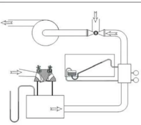
The fluid dynamic efficiency of the intake apparatus has been investigated at a steady flow rig, enabling air to be forced through the system by means of a blower while the valve lift is fixed to a selected value (fig. 1). Temperature and pressure transducers have been used to character-ise the conditions of the ambient and inside the cylinder, while a laminar flow meter system has been adopted to measure the global mass flow rate [31].
The facility also enables local velocity measurements with LDA. To this purpose, opti-cal access to the cylinder was obtained through a window perpendicular to the cylinder axis. The Table 1. Main engine characteristics
Engine Four-stroke
LDA system is a one-colour system (i. e. capable of measuring one component of the velocity) in a back-scattering configuration, with a Bragg-cell fre-quency shifter. The system uses a continuous ar-gon-ion laser as light source (2 W on the green line, atl= 514.5 nm) and optical fibres for both transmit-ting and collectransmit-ting optics. The transmittransmit-ting optics include a beam splitter and a focusing lens, while the receiving optics consists of a focusing lens, a photodetector and an interference filter. The main geometrical data of the optical system are given in tab. 2.
If a frequency shifter module is used, the number of fringes depends on other parameters, such as record length, centre frequency, and band width used by the signal processor. In the case of the reported measurements, the resulting number of fringes was 48.
The movement of the LDA probe is obtained by using a micrometer x-y traversing system. The probe can also be rotated around its axis and moved vertically (z-axis). A dedicated signal processor, which performs fast-Fourier transform (FFT) pro-cessing of the original signal in order to extract the Doppler frequency, is used for the analysis of the Doppler signal and ensures rejection of the signal
pro-duced by different particles that may be present within the measuring volume at the same time. The processor is linked to a computer in order to store and analyse the data.
For the seeding system a fluidised bed-like scheme was employed. A fraction of the inlet air is first dried and then passed through a horizontal porous diaphragm on the top of which a layer of silica “micro-balloons” is deposited. The air stream then carries the particles and is sub-sequently mixed with the main intake air at the engine inlet.
Methodology
A twofold approach has been employed to analyse the fluid dynamic behaviour of the intake system. The engine head has been examined in terms of global performances and in terms of local velocity measurements. In particular, the discharge coefficients are used to define the head breathability, while the LDA technique is adopted to determine the flow field inside the combustion chamber.
The configurations with both inlet valves open and with only one valve open have been compared in order to evaluate the interference phenomena between the two intake valves and to study the effect of the valve deactivation strategy.
Discharge coefficients
The discharge coefficients have been used to define the global fluid dynamic effi-ciency of the intake system [1]. Specifically, the dimensionless coefficient is defined as the ratio of the measured mass flow ratem&meas to reference mass flow ratem&r:
Figure 1. Steady flow rig
Table 2. Optical system data
Beam spacing 38 mm Focal length 400 mm Probe volume width 0.194 mm
Probe volume length 4.09 mm Number of fringes 35
C m m d meas r = & & (1)
If the flow is subsonic, the reference mass flow rate is given by:
&
m A p
T p p p p C
r r C
R
= æ
è çç ö
ø
÷÷ - -æ è çç ö ø ÷÷ é ë -0 0 0 1 0 1 2 1 1 g g g g g ê ê ê ù û ú ú ú (2)
while, if the flow is choked, the mass flow is formalised as:
& ( )
m A p
T r r R = + æ è ç ö ø ÷ + -0 0 1 2 1 2 1 g g g g (3)
wherep0is the intake system pressure,pC– the cylinder pressure,T0– the intake system temper-ature, andAr– the reference area.
Specifically, the reference areaArefis the valve curtain area and, therefore, it is a linear function of valve liftLv[18]:
Ar=pDvLv (4)
Furthermore, absolute discharge coefficientsCabswere defined to characterise the in-take system efficiency independently of the valve lift [32]:
Cabs Am
Ad =f
f (5)
wherefAdrepresents the dimensionless theoretical flow rate downstream of the valve, based on the isentropic flow condition:
f g
g
g g
Ad = -æ
è çç ö
ø ÷÷ -æ
è çç ö ø ÷÷ é ë ê ê ê ù û ú ú ú + 2 1 0 2 0 1 p p p p
C C (6)
whilefAmis the dimensionless actual flow rate, averaged over the dimensionless valve lift:
fAm r
meas r v v v v = ò æ è çç ö ø ÷÷ & ( / ) max. max. m
A a d
L D L
D
Lv Dv
0 0 0
(7)
wherer0is the air density anda0– the sound speed.
Measurements have been taken for a fixed ambient-cylinder pressure drop (7.3 kPa), while the dimensionless valve lift (Lv/Dv) has been set in the 0.050-0.400 interval. The overall uncertainty of dimensionless flow coefficients – evaluated according to literature [33, 34] – was consistently lower than 3%, and it decreased with valve lift.
LDA Measurements
di-vided into four sectors, which are referred to as sector A (valve-wall interaction zone), sector B (backward flow zone), sector C (valve-valve interaction zone), and sector D (forward flow zone).
At each point, two velocity components (along the x-and y- directions) have been recorded in a plane perpendic-ular to the valve axis. Ten thousand samples have been col-lected for each velocity component. The relative uncer-tainty on the LDA measurements, which is mainly due to the set-up of the electronic system, was lower than 2.2% [35, 36]. The valve lift has been fixed atLv/Dv= 0.375 with an ambient-cylinder pressure dropDp= 7.3 kPa, and the measuring plane has been located at 3/4 of the valve lift. To verify the previous measurements, a third component has
been acquired and it has been compared to the value calculated from the x and y components, re-cording a good agreement.
Results
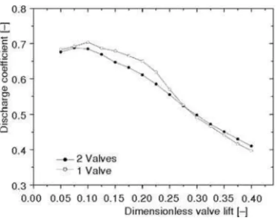
The global fluid dynamic efficiency of the four-valve ICE has been investigated in terms of discharge coefficients as a function of the dimensionless valve lift (Lv/Dv). To this pur-pose, the wide open throttle (WOT) configuration has been considered and the ambient-cylinder pressure dropDphas been set to 7.3 kPa.
Figure 3 compares the head permeability of the configurations with both inlet valves open and with only one valve open. The analysis highlights the presence of three regions, which cor-respond to different flow regimes, in line with the literature [1, 37]. In particular, for low valve lift, high values of the discharge coefficient and a progressive increase with the valve lift are ob-served. In these conditions the flow remains attached to the valve seat and head, due to the high viscous phenomena, and the entire curtain area is properly used. When the valve lift increases, a flow separation occurs at the valve head. As a consequence, a reduction in the effective flow area is produced and a progressive decrease in the head volumetric performances is registered. Successively, the presence of separation phenomena also at the valve seat reduces the fluid dy-namic efficiency of the intake system with a
fur-ther fall in the discharge coefficient.
Furthermore, the results put in evidence the large influence of interference phenomena be-tween the two valves on the global efficiency of the intake system. Specifically, the absence of flow interactions between the two intake valves leads to a better filling of the cylinder when a single valve is open and Lv/Dv £ 0.275. For higher lift, the previous trend is inverse, proba-bly due to significant irregularities that are gen-erated in the flow at the bifurcation of the intake ducts when only one valve is open. The largest differences are registered in the valve lift range 0.200-0.225, with a 6% higher value when a valve is deactivated.
Figure 2. Measuring points around the intake valves
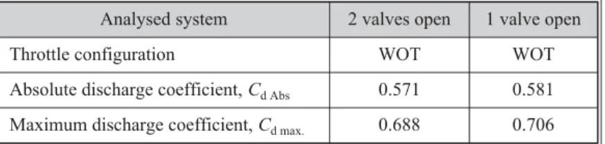
Table 3 shows the absolute and maximum discharge coefficients for the two configu-rations. The data illustrate that higher values are registered when only one valve is open and that the difference between the two arrangements is about 1.8% and 2.7% in terms of absolute and maximum discharge coefficients, respectively. Furthermore, the analysis put in evidence that whenLv/Dv£0.225 the discharge coefficients maintain values larger than the absolute coeffi-cient, which corresponds to about 82.5% of the maximum discharge coefficient.
Table 3. Absolute and maximum discharge coefficients for the intake system
Analysed system 2 valves open 1 valve open Throttle configuration WOT WOT Absolute discharge coefficient,Cd Abs 0.571 0.581 Maximum discharge coefficient,Cd max. 0.688 0.706
To examine the flow distribution within the com-bustion chamber and to evaluate the influence of the valve-valve interaction in more detail, the LDA technique has been adopted. Specifically, measurements around the intake valve curtain have been carried out by fixing the valve lift ratio atLv/Dv= 0.375 and by locating the measur-ing plane at 3/4 of the lift. The ambient-cylinder pressure drop has been imposed equal to 7.3 kPa and the WOT con-figuration has been considered.
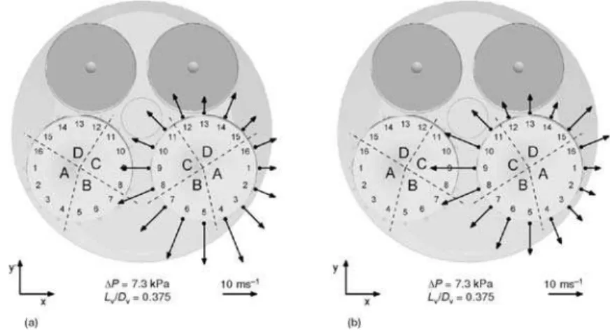
Figure 4 highlights the mean velocity distribution around the intake valve when the other inlet valve is com-pletely deactivated. The mean flow appears quite uniform, with lower velocities registered in sector A and the maxi-mum values found towards the centre of the combustion chamber (sector C). Furthermore, the figure shows that the mean velocity direction is close to the radial direction, with some deviation at points 8-9 (owing to the intake duct ori-entation), on the arc 15-3 (due to the influence of the cylin-der wall), and at points 12-14 (due to the wake of the valve stem).
A significant distortion in the mean flow is regis-tered when both valves are open (fig. 5). Specifically, the valve-valve interference phenomena produce a significant decrease in the mean velocity magnitudes and a reorienta-tion of the velocity vectors towards the y-axis in region C. The comparison in the valve-valve interaction zone put in evidence a mean 30% reduction in the velocity magnitudes when both intake valves are open and a 43% decrease at point 9, where the largest interference phenomena are pres-ent. When the two valves are open the higher velocities are registered in the region between points 10 and 1, with the maximum located at point 16 (73.5 m/s).
Figure 4. Velocity vectors around the intake valve when the other inlet valve is deactivated
The influence of the valve-valve interference phenomena can be observed also on the RMS velocity distribution in the valve curtain area. To this purpose, fig. 6 shows the velocity standard deviation on the radial velocity for the two head configurations. When a valve is deac-tivated, more uniform standard deviations are observed. The highest RMS values are found in region B as a result of the high distortion in the flow pathlines due to the flow inversion in the in-take duct, while the arc 10-15-2 is characterised by RMS values lower than 10 m/s. If the two valves are open, the largest RMS values move to region C, owing to the high interference be-tween the fluxes from the intake valves, and the maximum is found at point 9 (16.4 m/s). In the “valve-valve interference” zone, a mean increase of about 30% in the RMS values is registered with respect to the configuration with only one valve open. On the other hand, points 12-13-14 and 1-2-3 exhibit RMS values always lower than 7.5 m/s.
Finally, the comparison between the two engine configurations (one and both valves open) has been done considering the mean flow rates per sector. To this purpose, the height of the column bars in fig. 7 is proportional to the percentage volumetric flow rate per zone. The his-togram shows clearly that the interference
phe-nomena influence significantly the distribution of the flow around the valves. In fact, when the two intake valves are open, a noticeable de-crease (larger than 8.3%) in sector C is present. At the same time, the plot put in evidence that the interference phenomena produce a redistri-bution of the flow around the valves, with the flow that tends towards the region where a larger degree of freedom is present. Conse-quently, a 4.4% increase in the mean flow rate is registered in the valve-wall interference zone (region A) and a slight upsurge is also evident in sector D (the forward-flow zone) and in sector B (the backward-flow zone), with a 2.1 and 1.8% raise, respectively.
Figure 6. RMS velocity values around the intake valve for the configuration with only one valve open (a) and for the configuration with two valves open (b)
Conclusions
An experimental investigation has been carried out to characterise the fluid dynamic efficiency of a high performance ICE. Specifically, the work has been focused on a four-valve engine during the intake phase. To this purpose, measurements have been performed at a steady flow rig. Discharge coefficients have been used to characterise the global engine permeability while the LDA technique has been employed to give information on the flow distribution around the intake valve curtain area and on the interference phenomena between the two valves.
The global analysis has revealed the noticeable effect of the valve lift on the volumet-ric efficiency of the intake system. Specifically, different flow regimes have been observed and flow separation phenomena at the valve head and seat have been noticed at medium and high valve lifts.
Moreover, the analysis has highlighted that the valve-valve interference phenomena has a large effect on the engine head breathability. To this purpose, the dimensionless coeffi-cients of the usual configuration with the two intake valves open have been compared with the results registered when an intake valve is deactivated. The absence of flow interactions between the two intake valves leads to a better filling of the cylinder when a single valve is open at low and medium valve lift. Conversely, at high valve lifts the configuration with both intake valves open presents better results due to the reduction in the flow irregularities at the bifurcation of the intake ducts.
Furthermore, LDA measurements have permitted the analysis of the flow field within the combustion chamber and the more detailed definition of the influence of the valve-valve in-terference phenomena. When only one valve is open, the mean flow appears quite uniform and the velocity direction is quite close to the radial direction. A distortion of the flow field and a sig-nificant decrease in the velocity magnitude have been found in region C when the two intake valves are open. Moreover, a redistribution of the flow along the entire valve periphery has been observed, with an increase in the regions A, B, and D. The analysis of the rms velocity distribu-tion confirms the effect of the flow interference, with the highest values registered in the valve-valve interaction zone when the two intake valves are open.
Nomenclature A – area, [mm2]
a – sound speed, [ms–1]
B – bore, [mm]
Cabs – absolute flow coefficient, [–]
Cd – discharge coefficient, [–]
D – diameter, [mm]
Dv – valve diameter, [mm]
L – stroke, [mm]
Lv – valve lift, [mm];
&
m – mass flow rate, [kgs–1]
N – number, [–]
Dp – ambient-cylinder pressure drop, [Pa]
p0 – ambient pressure, [Pa]
pC – cylinder pressure, [Pa]
T0 – ambient temperature, [°C] Greek symbols
l – wavelength of the laser beam, [nm] r – air density, [kgm–3]
fAd – dimensionless theoretical flow rate, [–]
fAm – dimensionless actual flow rate, [–] Subscripts
abs – absolute c – cylinder i – intake e – exhaust meas – measured r – reference v – valve 0 – ambient Acronyms
References
[1] Heywood, J. B., Internal Combustion Engine Fundamentals, Mc Graw Hill, New York, USA, 1998
[2] Jovanovi}, Z. S.,et al., The Effect of Combustion Chamber Geometry Lay-Out on Combustion and
Emis-sion,Thermal Science, 12(2008), 1, pp. 7-24
[3] Morrone, P., Algieri, A., Numerical Investigation on the Energetic Performances of Conventional and Pel-let Aftertreatment Systems in Flow-Through and Reverse-Flow Designs,Thermal Science, 15(2011), 4, pp. 1049-1064
[4] Algieri, A.,et al., Energy Efficiency Analysis of Monolith and Pellet Emission Control Systems in Unidi-rectional and Reverse-Flow Designs,SAE International Journal of Engines, 2(2010), 2, pp. 684-693 [5] Barzegar, R.,et al., Combustion Fluid Dynamics Simulation of the Combustion Process, Emission
Forma-tion and the Flow Field in an In-Direct InjecForma-tion Diesel Engine,Thermal Science, 17(2013), 1, pp. 11-23, doi: 10.2298/TSCI111218108B (in this issue)
[6] Zhijun, W., Zhen, H., In-Cylinder Swirl Formation Process in Four-Valve Diesel Engine,Experiments in Fluids, 31(2001), 5, pp. 467-473
[7] Jebamani, D. R.,et al., Studies on Variable Swirl Intake System for DI Diesel Engine Using Computa-tional Fluid Dynamics,Thermal Science, 12(2008), 1, pp. 25-32
[8] Desantes, J. M.,et al., Air Mass Flow Estimation in Turbocharged Diesel Engines from In-Cylinder Pres-sure MeaPres-surement,Experimental Thermal and Fluid Science, 34(2010), 1, pp. 37-47
[9] Moore, W.,et al., Charge Motion Benefits of Valve Deactivation to Reduce Fuel Consumption and Emis-sions in a GDi, VVA Engine, SAE technical paper 2011-01-1221, 2011
[10] Coltman, D.,et al., Project Sabre: A Close-Spaced Direct Injection 3-Cylinder Engine with Synergistic Technologies to Achieve Low CO2Output, SAE technical paper 2008-01-0138, 2008
[11] Sellnau, M.,et al., 2-Step Variable Valve Actuation: System Optimization and Integration on an SI En-gine, SAE technical paper 2006-01-0040, 2006
[12] Patel, R.,et al., Un-Throttling a Direct Injection Gasoline Homogeneous Mixture Engine with Variable Valve Actuation,International Journal of Engine Research, 11(2010), 6, pp. 391-411
[13] Jemni, M. A.,et al., Influence of Intake Manifold Design on In-Cylinder Flow and Engine Performances in a Bus Diesel Engine Converted to LPG Gas Fuelled, Using CFD Analyses and Experimental Investiga-tions,Energy, 36(2011), 5, pp. 2701-2715
[14] Jovanovi}, Z. S., et al., The Effect of Bowl-In-Piston Geometry Layout on Fluid Flow Pattern,Thermal
Science, 15(2011), 3, pp. 817-832
[15] Jasak, H., et al., Rapid CFD Simulation of Internal Combustion Engines, SAE technical paper 1999-01-1185, 1999
[16] Ramanathan, S.,et al., EGR and Swirl Distribution Analysis Using Coupled 1D-3D CFD Simulation for a Turbocharged Heavy Duty Diesel Engine, SAE technical paper 2011-01-2222, 2011
[17] Kang, K. Y., Baek, J. H., LDV Measurement and Analysis of Tumble Formation and Decay in a Four-Valve Engine,Experimental Thermal and Fluid Science, 11(1995), 2, pp. 181-189
[18] Xu, H., Some Critical Technical Issues on the Steady Flow Testing of Cylinder Heads, SAE technical pa-per 2001-01-13, 2001
[19] Pajkovi}, V. R., Petrovi}, S. V., Spatial Flow Velocity Distribution around an Inlet Port/Valve Annulus,
Thermal Science, 12(2008), 1, pp. 73-83
[20] Blair, G. P.,et al., Some Fundamental Aspects of the Discharge Coefficients of Cylinder Porting and Ducting Restrictions, SAE technical paper 980764, 1998
[21] Blair, G. P., Drouin, F. M. M., Relationship between Discharge Coefficients and Accuracy of Engine Sim-ulation, SAE technical paper 962527, 1996
[22] Bohac, S. V., Landfahrer, K., Effects of Pulsating Flow on Exhaust Port Flow Coefficients, SAE technical paper 1999-01-0214, 1999
[23] Ismail, A. R., Bakar, R. A., Semin, Valve Flow Discharge Coefficient Investigation for Intake and Exhaust Port of Four Stroke Diesel Engines,Journal of Engineering and Applied Sciences, 2(2007), 12, pp. 1807-1811
[24] Son, J.-W.,et al., A Correlation Between Re-Defined Design Parameters and Flow Coefficients of SI En-gine Intake Ports, SAE technical paper 2004-01-0998, 2004
[25] Algieri, A., An Experimental Analysis of the Fluid Dynamic Efficiency of a Production Spark-Ignition Engine during the Intake and Exhaust Phase,ISRN Mechanical Engineering,2011(2011), ID427976 [26] Ismail, A. R.,et al., Engine Power Calculation Using Air Flow through Engine from Flowbench Test Flow
of Four Stroke Direct Injection Diesel Engines,Journal of Engineering and Applied Sciences, 2(2007), 12, pp. 1812-1817
[27] Chan, V. S. S., Turner, J. T., Velocity Measurement Inside a Motored Internal Combustion Engine Using Three-Component Laser-Doppler Anemometry,Optics & Laser Technology, 32(2000), 7-8, pp. 557-566 [28] Begg, S. M.,et al., Low Intake Valve Lift in a Port Fuel-Injected Engine,Energy, 34(2009), 12, pp.
2042-2050
[29] Krishna, B. M., Mallikarjuna, J. M., Characterization of Flow Through the Intake Valve of a Single Cylin-der Engine Using Particle Image Velocimetry,Journal of Applied Fluid Mechanics, 3(2010), 2, pp. 23-32 [30] Bevan, K. E., Ghandhi, J. B., PIV Measurements of in-Cylinder Flow in a Four-Stroke Utility Engine and
Correlation with Steady Flow Results, SAE technical paper 2004-32-0005, 2004 [31] ***, Meriam, Laminar Flow Elements – User Manual, 2011
[32] Auriemma, M., et al., Fluid-Dynamic Analysis of the Intake System for a HDDI Diesel Engine by STAR-CD Code and LDA Technique, SAE technical paper n. 2003-01-0002, 2003
[33] Doebelin, E. O., Measurement System Application and Design, Mc Graw Hill, New York, USA, 1990 [34] Algieri, A.,et al., Experimental and Numerical Investigation on the Effects of the Seeding Properties on
LDA Measurements,Journal of Fluids Engineering, 127(2005), 3, pp. 514-522
[35] Algieri, A.,et al., Influence of Valve-Lift and Throttle Angle on the Intake Process in High Performance Motorcycle Engine,Journal of Engineering for Gas Turbine and Power, 128(2006), 4, pp. 934-941 [36] Algieri, A., et al., Numerical and Experimental Analysis of the Intake Flow in a High Performance
Four-Stroke Motorcycle Engine,Journal of Engineering for Gas Turbines and Power, 129(2007), 4, pp. 1095-1105
[37] Weclas, M.,et al., Unsteady Intake Valve Gap Flow, SAE technical paper 952477, 1995