Abstract
Dynamic characteristics of the priority control system are of great influence to the control effect, response speed, and working stability of the high-speed on–off digital valve. The main focus of this study is on revealing the dynamic proper-ties of the priority control system for a developed high-speed on–off digital valve. In this article, a detailed introduction to the high-speed on–off digital valve and its priority control system is performed first, which includes the system func-tion, structural composifunc-tion, and operation principle. Thereafter, a simulation model of the priority control system is established using the AMESim software and the dynamic characteristics are simulated. Simulation results including the variations in the pulse-width modulation signal, coil current, and the main spool displacement of the directional valve are presented and discussed. They indicate that the opening time of the main spool increases with the duty ratio of the vol-tage signal. Moreover, the main spool displacement is basically equal in one single pulse-width modulation signal cycle, and thus, it is proportional to the cycle number of the pulse-width modulation signal. As a consequence, the priority control system possesses a good dynamic characteristic for the high-speed on–off digital valve as a pilot valve to achieve proportional control of main spool displacement for the directional valve.
Keywords
High-speed on–off digital valve, priority control system, dynamic characteristic, AMESim software
Date received: 10 October 2014; accepted: 4 March 2015
Academic Editor: Mario L Ferrari
Introduction
A high-speed on–off digital valve (HSDV) is essentially a throttle valve with its opening and closing being con-trolled by the high–low level of a pulse-width modula-tion (PWM) signal.1–4 The flow control of HSDV can be achieved through adjusting the on–off time ratio, namely duty ratio.5Generally, the HSDV serves in only two states (opening and closing), which enables it to communicate directly with the computer so as to con-vert the digital signal into the pulse signal without any digital-to-analog (D/A) converter. In comparison with traditional on–off valves, it has considerable advan-tages, such as low cost, compact structure, antipollu-tion, high-speed responsibility, and energy saving.6–9
As a consequence, the HSDV holds a lot of prospective applications in various fields and equipment for pres-sure and position control, such as machinery industry, automobile, aviation, high-speed reciprocating drill, as well as crushing machine and printer.10,11
1School of Mechanical and Automotive Engineering, Hefei University of
Technology, Hefei, China
2Department of Modern Mechanics, University of Science and
Technology of China, Hefei, China
Corresponding author:
Yishan Zeng, School of Mechanical and Automotive Engineering, Hefei University of Technology, Hefei 230009, China.
Email: [email protected]
In consideration of the desirable characteristics asso-ciated with the HSDV, experts and scholars have con-ducted many relevant works and efforts on the structural design, specific application, and service per-formance of the HSDV. For instance, Yamada et al.12 developed a high-speed on/off digital valve for use in a hydraulic control system and found that the switching time of the valve is less than 0.7 ms. Rannow et al.13 utilized the high-speed on/off valve for the control of hydraulic systems as a way to avoid the inefficiency associated with the throttling valves. Fu et al.14 pro-posed a new method for testing the dynamic character-istics of the high-speed on–off valve by detecting the output pressure signal of the a-type half bridge. Ouyang et al.15 introduced an innovative high-speed on/off valve based on piezoelectric actuators and found that the maximal flow rate, pressure, and frequency of the valve were 11 L/min, 20 MPa, and 200 Hz, respec-tively, through simulation. Liu et al.16 researched on the precise position control of the hydraulic cylinder using the high-speed on–off valve. Wang et al.17,18 studied a novel hydraulic pressure-boost system utiliz-ing the high-speed on–off valve and they observed that the system pressure could be successfully boosted from 50 to 116 bar for a duty ratio of PWM signal of 0.7.
Priority control system (PCS) is the foundation for the effective work of the HSDV. Its performance directly affects the response speed, control effect, and work stability of the HSDV. However, there are indeed less works dealing with this essential issue as mentioned above. Therefore, the modeling and simulation are car-ried out on the dynamic properties of the PCS using the AMESim software. Simulation results concerning the PWM signal, coil current, as well as the main spool dis-placement of the directional valve under various work-ing conditions are obtained and discussed. Research results of this work can serve to provide a theoretical
guidance to the optimization design and practical appli-cation of the HSDV.
HSDV and its PCS
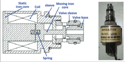
As shown in Figure 1, the HSDV is mainly composed of the static iron core, coil, sleeve, moving iron core, valve sleeve, valve base, and spring. Unlike the continu-ous control method adopted by the servo valve and proportional valve, the HSDV utilizes the pulse control method and the response time can be less than 1 ms.
Specific working process of the HSDV is summar-ized as follows: (a) the computer sends out the corre-sponding pulse signal according to the control requirements; (b) the pulse signal is modulated and amplified separately by a pulse-width modulator and a power amplifier, and then it is transmitted to the HSDV; (c) the high-speed forward and reverse move-ment of the HSDV spool is regulated by controlling the high-frequency electromagnetic force; (d) the on–off switching of the liquid flow is realized and the flow rate can be adjusted through controlling the opening time of the HSDV.
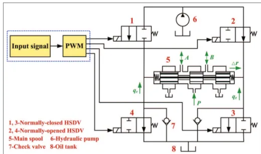
Figure 2 shows a set of HSDVs and its PCS. As plotted, a bridge circuit composed of four HSDVs is used as a pilot valve for the directional valve. Main spool displacement of the directional valve can be con-trolled through regulating the oil flow rate under the control of PWM signal. And then, the regulation of the flow rate of the directional valve can be achieved.
In Figure 2, the electromagnet is electrified when the PWM signal is 1 and the spool of normally closed HSDVs 1 and 3 open while that of normally opened HSDVs 2 and 4 turn off. At that time, the oil flows into the left pressure chamber of the main spool 5, and then it outflows from the right pressure chamber and into the oil tank 8 through the valve 3. On the contrary,
Figure 1. High-speed on–off digital valve (HSDV).
when the PWM signal changes from 1 to 0, the electro-magnet is powered off and the electroelectro-magnetic force disappears. At that time, the valve 1 becomes closed under the spring effect while the valve 3 remains closed due to the blocking effect of the check valve 7. Since the frequency of PWM signal is very high, the single opening time of the digital valve is extremely short. As a result, the oil quantity that flows into the main spool through the valve 1 is rarely little which hardly has any impact on the spool position. However, the average oil quantity per unit time is considerable due to the high-frequency on–off switching of the digital valve, which may make the main spool 5 move to the right. In prac-tical application, the average flow of the digital valve can be controlled by adjusting the duty ratio of the PWM signal, which can thereby control the displace-ment and speed of the main spool.
Simulation model of the PCS
Dynamic simulation is needed to verify the control properties of the PCS. The main purpose of the simula-tion includes (a) the analysis of the working perfor-mance of HSDV and (b) the verification of whether the usage of HSDV as a pilot valve can achieve the propor-tional control of the main spool position.
In this article, a simplification of the simulation sys-tem is carried out before the establishment of the simu-lation model. According to the analysis of pilot control process of the HSDV in section ‘‘HSDV and its PCS,’’ the PCS can be simplified as shown in Figure 3. Meanwhile, the movement of the main spool in the cav-ity of the directional valve can be regarded as the movement of piston in the cylinder. Then, the simula-tion model of the PCS is established as plotted in
Figure 2. Priority control system for the high-speed on–off digital valve.
Figure 3. Simplified drawing of the PCS.
Figure 4. In addition, according to the design para-meters of the HSDV and its PCS, the main simulation parameters of each component in the model are set as given in Table 1.
Results and discussion
PWM signal, coil current, and main spool
displacement
As stated above, the displacement and speed of the main spool are controlled by regulating the duty ratio of the PWM signal. In the case of a duty ratio of high-voltage signalt1= 0.1 and a duty ratio of total voltage
signal t2= 0.5, the variations in PWM signal, coil
current, and main spool displacement with time are obtained as depicted in Figure 5.
As seen in Figure 5, we can draw the following conclusions.
1. When the starting output voltage of the ampli-fier circuit is high, it may generate a large cur-rent to the coil. Then, the spool becomes to open at a high acceleration due to a great elec-tromagnetic force. Moreover, it can be seen from the figure that the required time for the spool to reach the fully open state, that is, the opening timeton, is 2 ms.
2. Once the spool is fully opened, only a small elec-tromagnetic force is needed for the HSDV to
Figure 4. Simulation model of the PCS for HSDV.
PCS: priority control system; HSDV: high-speed on–off digital valve.
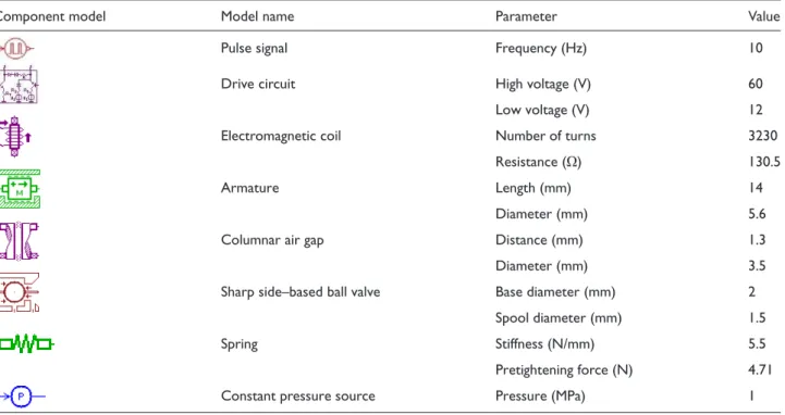
Table 1. Parameter setting of major components in the simulation model.
Component model Model name Parameter Value
Pulse signal Frequency (Hz) 10
Drive circuit High voltage (V) 60
Low voltage (V) 12
Electromagnetic coil Number of turnsResistance ( 3230
O) 130.5
Armature Length (mm)Diameter (mm) 145.6
Columnar air gap Distance (mm) 1.3
Diameter (mm) 3.5
Sharp side–based ball valve Base diameter (mm) 2
Spool diameter (mm) 1.5
Spring Stiffness (N/mm) 5.5
Pretightening force (N) 4.71
Constant pressure source Pressure (MPa) 1
Figure 5. Variations in PWM signal, coil current, and main spool displacement.
PWM: pulse-width modulation.
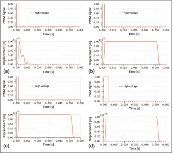
Figure 6. Variations in PWM signal and spool displacement for different duty ratios of high-voltage signal: (a)t1= 0.015, (b) t1= 0.02, (c)t1= 0.025, and (d)t1= 0.05.
remain in the open state. Therefore, the high voltage is cut off and the output voltage of the amplifier circuit turns to low-level state.
3. As the PWM signal begins to drop, the coil cur-rent decreases and the electromagnetic force reduces accordingly due to the effect of the diode freewheeling. Once the spring force is greater than the sum of the electromagnetic force and liquid pressure, the spool begins to close gradually. Meanwhile, the required time from the declining moment of the PWM signal to the closing moment of the spool, that is, the closing time toff, is obtained to be 5 ms as seen
in Figure 5.
Dynamic property for different duty ratios
Keeping the frequency of PWM signal to bef= 10 Hz and the duty ratio of total voltage current to be
t2= 0.5, the variations in PWM signal and spool
dis-placement with various duty ratios of high-voltage sig-nal can be obtained as seen in Figure 6. In Figure 6, the duty ratio of high-voltage signal t1is 0.015, 0.02,
0.025, and 0.05.
As seen in Figure 6, the spool cannot open fully when the duty ratio of high-voltage signal t1 is 0.015
until t1 increases to 0.02. Therefore, we can conclude
that the minimum value of t1 is about 0.02, that is, t1min= 0.02. In practice, a short time of high voltage is
better for reducing the hysteresis loss and coil heating in the precondition of satisfying the normally opened spool.
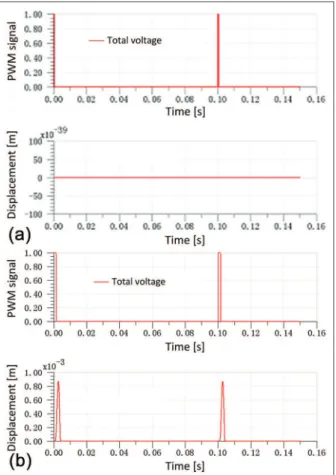
In addition, variation curves of PWM signal and spool displacement for two duty ratios of voltage signal (t1=t2=t= 0.005 and t1=t2=t= 0.015) are
obtained as shown in Figure 7.
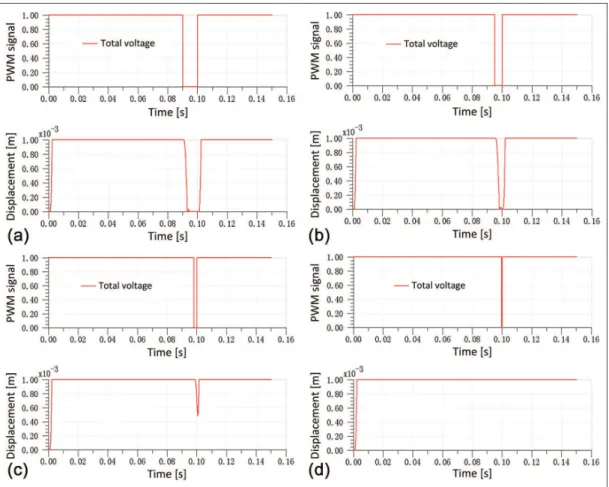
Keeping the duty ratio of high-voltage signal t1= t1min= 0.02 and regulating the duty ratio of total
vol-tage signalt2, the variations in PWM signal and spool
displacement for various values oft2are gained as
pre-sented in Figure 8. In this figure, the value oft2is 0.9,
0.95, 0.98, and 0.995.
In combination with Figures 7 and 8, the following conclusions can be drawn:
1. Whent2is very small (t2= 0.005), the
increas-ing time of the electromagnetic force is too short. And the maximum electromagnetic force is too small comparing to the required force value for opening the spool. Thus, the spool cannot open at this time.
2. For a value of t2= 0.015, the maximum
elec-tromagnetic force is able to overcome the spring effect and the spool begins to open. However, the electromagnetic force starts to decrease
before the spool is fully open which makes the spool close gradually.
3. While the value oft2increases to 0.98, the
elec-tromagnetic force starts to increase before the spool is fully open due to the short declining time of the electromagnetic force. This phenom-enon leads the spool to overcome the spring effect and start to open.
4. Once the value of t2 reaches up to 0.995, the
spring effect is insufficient to induce the spool to open because the declining time of electromag-netic force is very short and the electromagelectromag-netic force is great enough to overcome the spring effect. Therefore, the spool maintains the open state under this circumstance.
Pilot proportional control performance
Figure 9 indicates the variations in PWM signal, spool displacement of HSDV, and main spool displacement with time in the case of t1= 0.02 and t2= 0.5. It can
be seen from Figure 9 that the oil flows into the cavity
Figure 7. Variation curves of PWM signal and spool
displacement for two duty ratios of voltage signal: (a)t= 0.005
and (b)t= 0.015.
PWM: pulse-width modulation.
of the main spool to push the spool to move while the spool of the HSDV is open. Also, the main spool dis-placement presents an approximately linear relationship with time, just as depicted in the main spool displace-ment curve. Therefore, the proportional control of main spool displacement is achieved by the regulation of the average oil flow while using the HSDV as a pilot valve. Therefore, further research on the main spool
Figure 8. Variations in PWM signal and spool displacement for various duty ratios of total voltage signal: (a)t2= 0.9, (b)t2= 0.95,
(c)t2= 0.98, and (d)t2= 0.995. PWM: pulse-width modulation.
Figure 9. Variations in PWM signal, spool displacement of HSDV, and main spool displacement.
PWM: pulse-width modulation; HSDV: high-speed on–off digital valve.
displacement is required to verify the proportional con-trol effect of the PCS.
Main spool displacement in several cycles is obtained as plotted in Figure 10. In this figure, the total simula-tion time is extended to 0.5 s. As can be seen, the main spool displacement in one single cycle presents basically the same. Thus, we can conclude that the main spool displacement is proportional to the cycle number of PWM signal. In practice, proportional control of the main spool displacement can be achieved by adjusting the cycle number of PWM signal. Overall, the PCS of HSDV is capable for the proportional control of the main spool displacement.
Conclusion
This article presents a dynamic simulation and analysis of the dynamic characteristics of the PCS for HSDV as a pilot valve for the directional valve. The simulation was carried out using the AMESim software. Simulation results concerning the PWM signal, coil current, spool displacement of HSDV, and main spool displacement were presented and discussed. They indi-cate that the opening time of the main spool for the directional valve increases with the duty ratio of the voltage signal. Moreover, the main spool displacement is basically the same in one single cycle of the PWM signal. As a consequence, it is proportional to the cycle number of the PWM signal. On the whole, the designed PCS is proved to possess a good dynamic characteristic for the HSDV as a pilot valve to achieve proportional control of main spool displacement for the directional valve.
Declaration of conflicting interests
The authors declare that there is no conflict of interest regard-ing the publication of this article.
Funding
This work was supported by the State Key Development Program for Basic Research of China (2011CB707305) and the Fundamental Research Funds for the Central Universities (2011HGZ10004).
References
1. Jeong HS and Kim HE. Experimental based analysis of the pressure control characteristics of an oil hydraulic three-way on/off solenoid valve controlled by PWM sig-nal.J Dyn Syst Meas Contr2002; 124: 196–205.
2. Ahn K and Yokota S. Intelligent switching control of pneumatic actuator using on/off solenoid valves. Mecha-tronics2005; 15: 683–702.
3. Huang SY and Hwang YR. A hybridization design of an air motor and an electric motor based on field
programmable gate array controller.Proc IME C J Mech Eng Sci2012; 226: 1778–1786.
4. Lv C, Zhang J, Li Y, et al. Hardware-in-the-loop simula-tion of pressure-difference-limiting modulasimula-tion of the hydraulic brake for regenerative braking control of elec-tric vehicles. Proc IME D J Automob Eng 2014; 228: 649–662.
5. Xiang Z, Tao G, Xie J, et al. Simulation and experimen-tal investigation on pressure dynamics of pneumatic high-speed on/off valves. J Zhejiang Univ 2008; 42: 845–849.
6. Branson DT III, Lumkes JH Jr, Wattananithiporn K, et al. Simulated and experimental results for a hydraulic actuator controlled by two high-speed on\off solenoid valves.Int J Fluid Power2008; 9: 47–56.
7. Di Gaeta A, Glielmo L, Giglio V, et al. Modeling of an electromechanical engine valve actuator based on a hybrid analytical—FEM approach. IEEE ASME Trans Mech2008; 13: 625–637.
8. Zhu K, Gu L, Chen Y, et al. High speed on/off valve control hydraulic propeller.Chin J Mech Eng 2012; 25: 463–473.
9. Liu Z, Gao Q, Deng G, et al. The position control of hydraulic cylinder based on high-speed on-off valve.Int J Model Ident Contr2014; 22: 54–67.
10. Adeli MR and Kakahaji H. Modeling and position slid-ing mode control of a hydraulic actuators usslid-ing on/off valve with PWM technique. In: Proceedings of the 3rd international students conference on electrodynamics and mechatronics (SCE’ 11), Opole, 6–8 October 2011, pp.59–64. New York: IEEE.
11. Liu Z, Gao Q, Yu C, et al. Collaborative synchronization digital control for double hydraulic cylinders.Adv Mech Eng2014; 2014: 1–18.
12. Yamada H, Wennmacher G, Muto T, et al. Development of a high-speed on/off digital valve for hydraulic control systems using a multilayered PZT actuator. Int J Fluid Power2000; 1: 5–10.
13. Rannow M, Tu H, Wang M, et al. Optimal design of a high-speed on/off valve for a hydraulic hybrid vehicle application. In:Proceedings of the 7th international fluid power conference, Aachen, 22–24 March 2010. Aachen: Apprimus Wissenschaftsver.
14. Fu L, Kong X and Qiu M. Test method of high-speed on-off valve dynamic characteristics.Chin J Mech Eng2006; 19: 63–66.
15. Ouyang XP, Yang HY, Jiang HY, et al. Simulation of the piezoelectric high-speed on/off valve.Chin Sci Bull2008; 53: 2706–2711.
16. Liu Z, Gao Q, Li J, et al. The research of hydraulic cylin-der controlled by digital valve.TELKOMNIKA Indones J Electr Eng2014; 12: 3873–3886.
17. Wang F, Gu L and Chen Y. A hydraulic pressure-boost system based on high-speed on-off valves.IEEE ASME Trans Mech2013; 18: 733–743.
18. Wang F, Gu L and Chen Y. A continuously variable hydraulic pressure converter based on high-speed on-off valves.Mechatronics2011; 21: 1298–1308.