Article
J. Braz. Chem. Soc., Vol. 21, No. 10, 1977-1985, 2010. Printed in Brazil - ©2010 Sociedade Brasileira de Química 0103 - 5053 $6.00+0.00
*e-mail: [email protected], [email protected]
Differential Pulse Voltammetric Determination of Hydroxylamine at an Indenedione
Derivative Electrodeposited on a Multi-Wall Carbon Nanotube Modiied Glassy
Carbon Electrode
Hamid R. Zare,* Fatemeh Chatraei and Navid Nasirizadeh
Department of Chemistry, Yazd University, 89195-741 Yazd, Iran
A eletrodeposição de ilmes inos de um derivado da indenodiona em eletrodo de carbono vítreo modiicado por nanotubos de carbono de paredes múltiplas (ECV-NTCPM), mostra um par de picos com características de coninamento em superfície. O eletrodo de carbono vítreo modiicado por NTCPM e pela indenodiona (ECV-NTCPMI) apresenta uma alta atividade catalítica para a eletro-oxidação de hidroxilamina. O potencial do pico anódico para a oxidação da hidroxilamina em ECV-NTCPMI é aproximadamente 140 mV, enquanto em ECV-NTCPM e em ECV modiicado pela indenodiona (ECV-MI), os potenciais de pico aparecem em aproximadamente 505 e 525 mV, respectivamente. Os resultados mostram que há um aumento da corrente do pico anódico de oxidação da hidroxilamina em ECV-NTCPMI quando comparado ao valor obtido com ECV-MI ou ECV-NTCPM. Os resultados também sugerem que a combinação de NTCPM com um mediador melhora, deinitivamente, as características de oxidação da hidroxilamina. Além disso, a voltametria de pulso diferencial exibe dois intervalos dinâmicos lineares de 1,0-10,0 e 10,0-100,0 µmol L-1
com sensitividade de 0,1955 e 0,0841 µA L µmol-1 respectivamente e um limite de detecção mais
baixo, de 0,8 µmol L-1 para hidroxilamina. A excelente reversibilidade eletroquímica do par redox,
a simplicidade técnica, e a boa atividade eletrocatalítica para hidroxilamina são as vantagens deste eletrodo modiicado. Finalmente, a atividade do ECV-NTCPMI foi também investigada para a determinação da hidroxilamina em duas amostras.
The electrodeposited thin ilms of an indenedione derivative on multi-wall carbon nanotubes modified glassy carbon electrode (MWCNT-GCE) shows one pair of peaks with surface conined characteristics. The indenedione MWCNT modiied GCE (IMWCNT-GCE) presents a highly catalytic activity toward hydroxylamine electro-oxidation. The anodic peak potential for hydroxylamine oxidation at IMWCNT-GCE is about 140 mV whereas at MWCNT-GCE and indenedione modiied GCE (IMGCE), the peak potentials appear at about 505 and 525 mV respectively. The results show that there is an enhancement of the anodic peak current of hydroxylamine oxidation at IMWCNT-GCE as compared to the value obtained at IMGCE or MWCNT-GCE. The results also suggest that a combination of MWCNT and mediator deinitely improves the characteristics of hydroxylamine oxidation. Furthermore, differential pulse voltammetry exhibits two linear dynamic ranges of 1.0-10.0 and 10.0-100.0 µmol L-1 with sensitivity
of 0.1955 and 0.0841 µA L µmol-1 respectively and a lower detection limit of 0.8 µmol L-1 for
hydroxylamine. Excellent electrochemical reversibility of the redox couple, technical simplicity, and good electrocatalytic activity for hydroxylamine are the advantages of this modiied electrode. Finally, the activity of IMWCNT-GCE was also investigated for hydroxylamine determination in two natural samples.
Keywords: hydroxylamine, multi-wall carbon nanotubes,modiied glassy carbon electrode, indenedione
Introduction
The electrocatalytic oxidation of hydroxylamine (NH2OH) has attracted many researches groups.1-6
nitrosothiols.8 Moreover, some hydroxylamine derivatives also constitute a great part of anticancer drugs.9 In addition, hydroxylamine has been shown to inactivate or inhibit a number of cellular enzymes and some viruses in vitro. It is also a skin irritant and sensitizer. Numerous methods have been developed for the determination of hydroxylamine.10-23 For example, chromatographic,10 spectrophotometric,11-13 and electrochemical,14-23 methods have been successfully applied to the determination of hydroxylamine. In this regard, we reported the preparation of a coumestan derivative modiied carbon paste electrode,19 and a rutin multi-wall carbon nanotubes modified glassy carbon electrode,20 and their application in the electrocatalytic oxidation of hydroxylamine. Also, some recent studies demonstrate the versatility of the use of derivatives nitroso/ hydroxylamine as electrochemical probes for some analytes of biological imprortance.24-27
Due to the unique properties of carbon nanotubes (CNTs) such as high surface area, chemical stability, and high electrical conductivity,28 the application of CNTs in fabrication of electrochemical sensors and biosensors has been studied by many research groups.30-34 The subtle electronic properties of carbon nanotubes suggest that they have the ability to promote electron transfer reaction when used as an electrode material in an electrochemical reaction, which provides a new way in the electrode surface modiication for designing new electrochemical sensors.20,29-36 Recently, we have used MWCNT modiied electrodes for electrocatalytic determination of some species.20,29,36,37 Owing to the importance of para -hydroquinone ring substituents on the reactivity of the mediator,36 it seems that using an indenedione derivative, with a para-hydroquinone ring in its structure could be important as a modiier and could yield some new information about the catalysis of some slow reactions. We recently described the electrochemical properties of the indenedione derivative MWCNT modiied carbon ceramic electrode (IMWCNT-CCE) and its application as a modiied electrode for detecting hydrazine.36 In this paper we report the characteristics of another modiied electrode which was prepared from the electrodeposition of an indenedione derivative (see Scheme 1 for structure) on MWCNT modified GCE (IMWCNT-GCE). The reactivity of this modiied electrode is also examined toward the electrocatalytic oxidation of hydroxylamine with the aim of inding its capabilities as an electron transfer mediator. In this report, we also investigate the electrochemical oxidation of hydroxylamine at MWCNT modiied GCE (MWCNT-GCE) and the indenedione derivative modiied GCE (IMGCE). The results show that some of the quantitative determination characteristics
of hydroxylamine at an IMWCNT-GCE are remarkably improved and also its overpotential is reduced, when compared to MWCNT-GCE and IMGCE. Finally, the analytical application of IMWCNT-GCE is described as a voltammetric detector for hydroxylamine determination in two water samples.
Experimental
Reagents and apparatus
The multi-wall carbon nanotubes with a diameter of 10-20 nm, a length of 5-20 µm, and a purity of >95% were purchased from Nanolab Inc. (Brighton, MA). Hydroxylamine, the chemicals used for preparation of buffer solutions, and other reagents had analytical grades from Merck and were used as received. The indenedione derivative (2-(2,5-dihydroxy-3,4-dimethylphenyl)-2-phenyl-2H-indene-1,3-dione), (see Scheme 1 for structure), was synthesized and puriied according to the procedure described recently.38 In the present paper, we refer to this indenedione derivative as indenedione for convenience. Doubly distilled water was used to prepare all the solutions. Buffer solutions (0.1 mol L-1) were prepared from H3PO4, and the pH was adjusted with NaOH solution. Hydroxylamine solution was freshly prepared just prior to use and all the experiments were carried out at a room temperature.
An Autolab potentiostat-golvanostat PGSTAT 30 (Eco Chemie, Ultrecht, the Netherlands) equipped with GPES 4.9 software, in conjunction with a three-electrode system and a personal computer was used for electrochemical measurements. A saturated calomel reference electrode (SCE), a platinum wire counter electrode, an indenedione derivative electrodeposited on a GCE (IMGCE), multi-wall carbon nanotubes modiied GCE (MWCNT-GCE), and an indenedione derivative electrodeposited on multi-wall carbon nanotubes modiied GCE (IMWCNT-GCE) were employed as working electrodes for the electrochemical studies. The pH was measured with a Metrohm model 691 pH/mV meter.
O O
OH
OH
CH3
CH3
Zare et al. 1979 Vol. 21, No. 10, 2010
Electrode preparation
The procedure of the working electrode pretreatment, activation and modiication was as follows. At irst, the GCE was carefully polished mechanically with 0.05 µm Al2O3 slurry on the polishing cloth to a mirror inish and then rinsed with doubly distilled water. For the electrochemical activation of the electrode, it was immersed in a 0.1 mol L-1 sodium bicarbonate solution and was activated by a continuous potential cycling from −1.1 to 1.6 V at a sweep rate of 100 mV s-1 until a stable voltammogram was obtained. For the preparation of MWCNT modiied GCE (MWCNT-GCE), a 5 µL of MWCNT-DMF suspension (1 mg per 1 mL) was placed directly onto the activated GCE surface and dried at a room temperature to form a MWCNT ilm at the GCE surface. The indenedione MWCNT modiied GCE (IMWCNT-GCE) was prepared by immersing of MWCNT-GCE in a 0.1 mol L-1 phosphate buffer (pH 5.0) containing 0.5 mmol L-1 indenedione. Then, indenedione was electrodeposited on the MWCNT-GCE surface by 10 continuous potential cycles from −400 to 800 mV at 100 mV s-1. For the preparation of indenedione modiied GCE (IMGCE), the activated GCE (AGCE) was rinsed with doubly distilled water and was modiied by 10 cycles of potential sweep between −400 and 800 mV at 100 mV s-1 in a 0.1 mol L-1 phosphate buffer solution (pH 5.0) containing 0.5 mmol L-1 indenedione. Finally, the modiied electrodes was rinsed thoroughly with water and stored in 0.1 mol L-1 phosphate buffer solution (pH 7.0).
Results and Discussion
Electrochemical behavior of IMWCNT-GCE
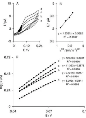
The cyclic voltammograms of an IMWCNT-GCE in a 0.1 mol L-1 phosphate buffer (pH 7.0) at various scan rates are shown in Figure 1A. When the potential is scanned between 0 to 210 mV, an excellent redox couple without a background current appears. We have recently reported that the indenedione derivative electrodeposited on a carbon ceramic electrode (CCE) modified with MWCNTs (IMWCNT-CCE) shows a weak redox couple that contaminates signiicantly the background current.36 In addition, the peak-to-peak separation of the redox couple of the electrodeposited indenedione derivative at a MWCNT-GCE is smaller than what is recently reported at IMWCNT-CCE. These results may be due to less conductivity of a carbon ceramic electrode as compared to GCE. Plots of the anodic and cathodic peak currents
versus the scan rate show a linear relationship (Figure 1B) as predicted theoretically for a surface-immobilized redox
couple.39 In addition, the formal potential (E0’) value, which was obtained from the equation of E0’ = E
p a – α(Ep.a−Ep.c), 40
is about 100 mV and for sweep rates ranging from 10 to 800 mV s-1 is almost independent of the potential scan rate. The results suggest that the values of anodic and cathodic peak potentials are proportional to the logarithm of the scan rate for scan rates higher than 350 mV s-1 (Figure 1C). In these conditions, the surface electron transfer rate constant (ks) and the charge transfer coeficient (α) for electron transfer between the indenedione and MWCNT-GCE can be estimated from the linear variation of the oxidation and reduction peak potentials with the logarithm of the sweep rate. This is according to Laviron theory.41 Based on this theory, the following equation can be used to determine the electron transfer rate constant between MWCNT-GCE and indenedione:
log ks = α log(1−α) + (1−α)log α− log (RT/nFv) −
α(1−α) nF ∆Ep/2.3RT (1)
In the present case, the values of ks and α were pH-dependent. We obtained ks and α values at four pH values and the results are summarized in Table 1. The data given in Table 1 reveal that α and ks values depend on the Figure 1. (A) Cyclic voltammetric responses of IMWCNT-GCE in 0.1 mol L-1 phosphate buffer (pH 7.0) at different scan rates. The
numbers 1 to 19 correspond to 10, 15, 20, 25, 30, 35, 40, 45, 50, 55, 60, 65, 70, 75, 80, 85, 90, 95 and 100 mV s-1 respectively. (B) Plots of anodic
media pH. Although, the ks has the greatest value in alkaline pH (pH 9.0), the modiied electrode is unstable in this pH. However, the results show that the ks values of IMWCNT-GCE are higher than those recently reported for IMWCNT-CCE.36 In addition, the surface coverage of the indenedione layer on the modiied electrode surface was evaluated from the cyclic voltammograms recorded at low scan rate in supporting electrolyte and using the equation Γ = Q/nFA, where Q is the charge obtained by integrating the anodic peak under the background correction and the other symbols have their usual meanings. In the present case, the calculated value of
Γ is 5.6×10⁻¹⁰ mol cm-2 at sweep rate 20 mV s-1 for pH = 7.0.
Electrocatalytic oxidation of hydroxylamine at IMWCNT-GCE
Figure 2 shows the cyclic voltammetric responses of a 0.1 mol L-1 phosphate buffer solution (pH 7.0) containing 6.0 mmol L-1 hydroxylamine at IMWCNT-GCE (curve b), MWCNT-GCE (curve c), IMGCE (curve d), and bare GCE (curve f). It can be seen that in the absence of hydroxylamine (Figure 2, curve a) a pair of well deined redox peaks for the indenedione ilm attached to MWCNT is observed. Upon the addition of 6.0 mmol L-1 of hydroxylamine, there is an enhancement of the anodic current peak and a very small current is observed in the cathodic peak (Figure 2, curve b). This is indicative of a very strong electrocatalytic effect. As illustrated, the anodic peak potential for hydroxylamine oxidation at IMWCNT-GCE (curve b) is about 140 mV which is close to that of the surface-conined mediator anodic peak potential in the absence of hydroxylamine. But at MWCNT-GCE (curve c) and IMGCE (curve d), peak potentials are about 505 and 525 mV respectively, and at the bare GCE, no current is observed in the presence of hydroxylamine (curve e). Table 2 shows the electrochemical characteristics of hydroxylamine oxidation on various electrode surfaces at pH 7.0. From Table 2, it is concluded that the best electrocatalytic effect for hydroxylamine oxidation is at IMWCNT-GCE. For example, according to the results, there is an enhancement of the anodic peak current at IMWCNT-GCE (curve b) relative to the value
obtained at MWCNT-GCE (curve c) and IMGCE (curve d). Also, the peak potential of hydroxylamine oxidation at IMWCNT-GCE (curve b) shifts by about 365 and 385 mV toward the negative values compared with that at a MWCNT-GCE (curve c) and IMMWCNT-GCE (curve d) respectively. In other words, as the data obtained clearly show, the combination of MWCNT and a mediator (the indenedione derivative) deinitely improves the characteristics of hydroxylamine oxidation. The improvement of the hydroxylamine determination sensitivity at IMWCNT-GCE is due to the enhancement of the effective surface area of the modiied electrode as well as the electrocatalytic effect of indenedione in the ErCi catalytic mechanism (ErC′i) which has been described in equations 4 and 5.34 Also, MWCNT accelerate the rate of heterogeneous electron exchange between the electrode surface and the analyte.42,43 This may be due to the MWCNT dimensions, the channels that Table 1. The surface charge transfer rate constant, ks, and the charge
transfer coeficient, α, for the electron transfer between MWCNT-GCE and the electrodeposited indenedione derivative at various pH
pH ks /(s-1) α
3 3.85 ± 0.10 0.54
5 4.39 ± 0.24 0.50
7 4.28 ± 0.07 0.51
9 10.27 ± 0.22 0.49
Figure 2. Cyclic voltammograms of the IMWCNT-GCE in 0.1 mol L-1
phosphate buffer solution (pH 7.0) at scan rate 20 mV s-1 in (a) absence
and (b) presence of 6.0 mmol L-1 hydroxylamine. (c), (d) and (e) show
the cyclic voltammograms of MWCNT-GCE, IMGCE and bare GCE in the presence of 6.0 mmol L-1 hydroxylamine and (f) shows the cyclic
voltammogram of the bare GCE in the absence of hydroxylamine.
Table 2. Comparison of electrocatalytic oxidation characteristics of hydroxylamine (6.0 mmol L-1) on various electrode surfaces at pH 7.0
Name of electrodea Oxidation peak
potential/mV
Oxidation peak current/ µA
MWCNT-GCE 505 17.8
IMGCE 525 17.4
IMWCNT-GCE 140 28.9
aMWCNT-GCE: multi-wall carbon nanotubes modiied glassy carbon
Zare et al. 1981 Vol. 21, No. 10, 2010
are inherently present in the tubes, the electronic structure and the topological defects present on the tubes surface.44 Another possibility is the porosity effect of CNT on the electrochemical oxidation of the analyte.34 Compared to the bare electrode, and considering the porous interfacial layer of MWCNT-modiied GCE, an electron may penetrate through the conductive porous channels onto the electrode more easily, leading to a higher sensitivity. Therefore, MWCNT can be used as a new material for immobilization and electron transfer reactions of indenedione.
In order to optimize the electrocatalytic response of IMWCNT-GCE to hydroxylamine oxidation, the effect of different pH values (6.0-8.0) on the cyclic voltammetric responses of 6.0 mmol L-1 hydroxylamine solution was investigated (see Figure 3). The results indicate that with the increase of the pH, the stability of the modiied electrode decreases. It may be due to the conversion of indenedione to a more soluble anionic form which causes the modiier to be released from the electrode surface. The anionic form of indenedione is formed from deprotonation of one of the hydroxyl groups of the hydroquinone ring in the indenedine structure. Also, as it can be seen, there is the best sensitivity for hydroxylamine determination at pH 7.0. In addition, the anodic peak potential for hydroxylamine oxidation at the modified electrode is more negative at pH 6.0 and more positive at pH 8.0 as compared to the
surface-conined mediator anodic peak potential in the absence of hydroxylamine, while both peak potentials are close to each other at pH 7.0. These results suggest a more effective interaction of hydroxylamine with the indenedione ilm at neutral pH as compared to the slightly basic or acidic pH.
Chronoamperometric studies
The catalytic oxidation of hydroxylamine at IMWCNT-GCE surface was also studied by chronoamperometry. Chronoamperograms were obtained at different concentrations of hydroxylamine at a potential step of 200 mV (Figure 4A). For an electroactive material (hydroxylamine in this case) with a diffusion coeficient, D, the current corresponding to the electrochemical reaction (under diffusion control) is described by Cottrell equation:39
I = nFAD1/2C/π1/2t1/2 (2)
where D and C are the diffusion coeficient (cm2 s-1) and bulk concentration (mol cm-3) of the analyte respectively. Figure 4B shows the experimental plots of I versus t-1/2 with the best its for different concentrations of hydroxylamine employed. From the slopes of the resulting straight lines and using Cottrell equation we calculated an average diffusion coeficient of 3.22×10⁻⁷ cm2 s-1 for hydroxylamine. The calculated diffusion coeficient is in a good agreement with that previously reported for hydroxylamine.19
Figure 3. (A) Cyclic voltammograms of the IMWCNT-GCE in 0.1 mol L-1
phosphate buffer (pH 7.0) at scan rate 20 mV s-1 in (a) absence and
(b) presence of 6.0 mmol L-1 hydroxylamine. (B) and (C) as (A) in a
0.1 mol L-1 phosphate buffer solution pH 6.0 and pH 8.0 respectively.
Figure 4. (A) Chronoamperometric response of the IMWCNT-GCE in 0.1 mol L-1 phosphate buffer solution (pH 7.0) at potential step of 200 mV
for different concentrations of hydroxylamine. The letters (a) to (d) correspond to 0.1, 0.2, 0.4 and 0.6 mmol L-1 hydroxylamine. (B) Plots of
I versus t-1/2 obtained from the chronoamperograms. The equations from
Kinetic studies
The effect of scan rate on the electrocatalytic oxidation of hydroxylamine at IMWCNT modiied GCE was used to get information about the rate-determining step. Figure 5A shows the cyclic voltammograms of the modiied electrode in a 0.1 mol L-1 phosphate buffer (pH 7.0) containing 4.0 mmol L-1 hydroxylamine at different scan rates. Figure 5B shows that a plot of the catalytic peak current
versus the square root of scan rate is linear. This result indicates that, at a suficient overpotential, the process is diffusion rather than surface controlled, while it is the ideal case for quantitative applications.39 Also, from this plot, one can calculate an approximate total number of electrons in the overall oxidation of hydroxylamine (n) using the following equation for diffusion controlled electrochemically irreversible reaction:37,45
Ip=3.01×10⁵n[(1−α)n
α]
1/2AC bD
1/2ν1/2 (3)
where D is the diffusion coeficient of hydroxylamine (D = 3.22×10⁻⁷ cm2 s-1 obtained by chronoamperometry), Cb is the bulk concentration of hydroxylamine (4.0 mmol L-1), and A is the electrode surface area
(0.0314 cm2). Values for α and n
α which are deduced
from Tafel plots (see below) are 0.37 and 1 respectively. This produces an approximate value, n = 2.2 ca. 2, for the total number of electrons involved in the anodic oxidation of hydroxylamine. Similar values were also previously reported for the oxidation of hydroxylamine.15,19,20 Thus, the rate-determining step is given in equation 5 with a rate constant k’. In above conditions, for E
rCi catalytic (ErCi') mechanism, Andrieux and Saveant theoretical model46 can be used to calculate the catalytic rate constant, k’. Based on this theory, the average value of the catalytic rate constant between hydroxylamine and indenedione, k’, is calculated to be (4 ± 1) × 10-4 cm s-1. This result is very close to that obtained from RDE measurements (see next section). Thus, the process according to a catalytic mechanism (ErCi') could be expressed as follows:
k s
Indenedione(reduced form) Indenedione(oxidized form) + 2H+ + 2e− (4)
k'
2 Indenedione(oxidized form) + 2NH2OH → 2 Indenedione(reduced form)+ N2O + H2O (5)
The overall oxidation of hydroxylamine by the modiied electrode is given in equation 6.
2NH2OH → N2O + H2O + 4H+ + 4e− (6)
In order to obtain information about the rate-determining step, Tafel plots were drawn (Figure 5C), derived from points of the Tafel region of the cyclic voltammograms in Figure 5A. The results of polarization studies for electro-oxidation of hydroxylamine at IMWCNT-GCE show that, for all potential sweep rates, the average Tafel slope is 10.6 V-1 (Figure 5C). Referring to equation 7,39 the average Tafel slope of 10.6 V-1 agrees well with the charge transfer coeficient of α = 0.37, if the rate-determining step of the electrode process includes one electron transfer.
Tafel slope = (1 − α)nαF/ 2.3RT (7)
It is necessary to mention that, based on the literature review, the number of electrons involved in the rate determining step of various processes is one.19,20,36,37,39 In addition, the exchange current, i0, is obviously readily accessible from the intercept of the Tafel plots.39 The average value of the exchange current, i0, of hydroxylamine at IMWCN-GCE is found to be 0.53 µA. The transfer coeficient, α, is a measure of the symmetry of the energy barrier and the exchange current is proportional to the standard charge transfer rate constant, k0, between analyte and modiier.39
Figure 5. (A) Cyclic voltammograms of the IMWCNT-GCE in 0.1 mol L-1
phosphate buffer solution (pH 7.0) containing 4.0 mmol L-1 hydroxylamine
at scan rates: (a) 2, (b) 4, (c) 6 and (d) 8 mV s-1. The points are the data used
Zare et al. 1983 Vol. 21, No. 10, 2010
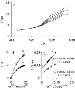
Rotating disk electrode measurements
The electrocatalytic activity of IMWCNT-GCE toward the oxidation of hydroxylamine was also evaluated using RDE voltammetry technique. RDE measurements were performed at different rotation speeds in a 0.1 mol L-1 phosphate buffer (pH 7.0) containing various concentrations of hydroxylamine. Typical examples of I-E curves (RDE voltammograms) for a 4.0 mmol L-1 hydroxylamine concentration at IMWCNT-GCE are presented in Figure 6A. The plots of catalytic currents measured at 135 mV versusω1/2 (Levich plots) are shown in Figure 6B. It can be seen that the clear lack of linearity immediately, suggests that the reaction is also limited by the electron transfer kinetics.39 In this case, Koutecky-Levich plots (Figure 6C) can be used to determine the value of the catalytic reaction rate constant, k’, between the oxidized form of indenedione and hydroxylamine. Koutecky-Levich equation can be formulated as follows:39
1/Icat= 1/ILev+ 1/Ik (8)
Here ILev is Levich current and Ik is the kinetic current. ILev and Ik are deined by equations 9 and 10:
ILev = 0.62nFAD2/3ω1/2ν −1/6C
b (9)
Ik = nFAk’Cb (10)
where ω is the angular frequency of rotation (rad s-1), ν the kinematic viscosity (cm2 s-1), and all other symbols have their own conventional meanings. From the above equation, it is apparent that the value of rate constant, k’, can be calculated from the intercepts of Koutecky-Levich plots (Figure 6C). From the intercepts of these plots, which are obtained by the measured currents at a potential of 135 mV, the mean value of k’ is found to be (7 ± 1) × 10-4 cm s-1. This value of k’is in a good agreement with that obtained by cyclic voltammetric measurements in previous section.
Differential pulse voltammetry measurements
Figure 7A shows the differential pulse voltammograms (DPVs) of various concentrations of hydroxylamine in a
Figure 6. (A) Typical example of rotating disk voltammograms in 0.1 mol L-1 phosphate buffer (pH 7.0) containing 4.0 mmol L-1
hydroxylamine at IMWCNT-GCE. The letters (a) to (f) correspond to rotation speeds of 500, 1000, 1500, 2000, 2500 and 3000 min-1. (B) Levich
plots for currents measured at Edisc = 135 mV in 0.1 mol L-1 phosphate
buffer (pH 7.0) containing (a) 3.0 and (b) 4.0 mmol L-1 of hydroxylamine.
(C) Koutecky-Levich plots obtained from Levich plot shown in (B). The points are the data and the lines are the best its to the data.
Figure 7. (A) Differential pulse voltammograms at IMWCNT-GCE in 0.1 mol L-1 phosphate buffer solution (pH 7.0) containing different
concentrations of hydroxylamine. The numbers 1 to 10 correspond to 1.0, 4.0, 6.0, 8.0, 10.0, 20.0, 40.0, 60.0, 80.0 and 100.0 µmol L-1
0.1 mol L-1 phosphate buffer (pH 7.0) at IMWCNT-GCE. The plot of the electrocatalytic peak current of hydroxylamine at the surface of IMWCNT-GCE, corrected for any residual current of the modiied electrode in supporting electrolyte, versus hydroxylamine concentration is shown in Figure 7B. This igure shows clearly that the calibration plot, constituted from two linear segments with different slopes, corresponds to two different ranges of 1.0-10.0 and 10.0-100.0 µmol L-1 hydroxylamine. The lower detection limit of hydroxylamine, Cm,was obtained to be 0.8 µmol L-1 using the equation Cm=3sbl/m,47 where s
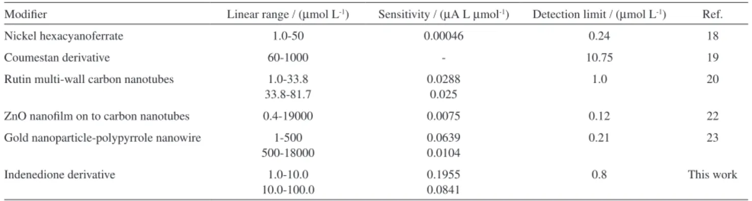
bl is the standard deviation of the blank response (µA) and m is the slope of the calibration plot (0.195 µA L µmol-1) in the irst linear range (1.0 to 10.0 L µmol-1). In Table 3, some of the electrocatalytic characteristics obtained in this work are compared with those previously reported by others.18-20,22,23 The data in Table 3 show that the responses of the proposed modiied electrode are in some cases, superior, especially the sensitivity, as compared to those reported for the other modiied electrodes.
Determination of hydroxylamine in tap and well water samples
From the results that are mentioned in the previous section, it is apparent that IMWCNT-GCE possesses a high sensitivity and a good detection limit to determine hydroxylamine in real samples. In order to test its practical application, the modiied electrode was used to determine
hydroxylamine in two natural water samples. For this propose, 5 mL of natural water sample was diluted to 10 mL with a 0.1 mol L-1 phosphate buffer solution (pH 7.0). Then, certain amounts of hydroxylamine were added and their recovery was determined by differential pulse voltammetry. The results (Table 4) show that the recoveries are within the range from 100.2 to 104.6%. The results that were obtained using the proposed method were validated against a calibration graph for hydroxylamine within a range of 10.0-100.0 µmol L-1. The results of the proposed method clearly show that the matrix of the natural water samples does not make any interference in determination of hydroxylamine.
Conclusions
The results of this study show that indenedione can be immobilized easily at the surface of a multi-wall carbon nanotubes (MWCNT) modified glassy carbon electrode (GCE). The indenedione MWCNT modiied GCE (IMWCNT-GCE) presents a stable and excellent electrocatalytic activity for hydroxylamine. The mean values of the catalytic rate constant, k’, of IMWCNT-GCE, for oxidation of hydroxylamine at different concentrations are found to be (7 ± 1) × 10-4 cm s-1 and (4 ± 1) × 10-4 cm s-1 respectively, using RDE voltammetry and cyclic voltammetry. It has been shown that differential pulse voltammetry can be used as analytical methods to determine hydroxylamine in various solutions. Finally, the proposed Table 3. Comparison some of electrocatalytic characteristics of used different modiiers for hydroxylamine determination
Modiier Linear range / (µmol L-1) Sensitivity / (µA L µmol-1) Detection limit / (µmol L-1) Ref.
Nickel hexacyanoferrate 1.0-50 0.00046 0.24 18
Coumestan derivative 60-1000 - 10.75 19
Rutin multi-wall carbon nanotubes 1.0-33.8 33.8-81.7
0.0288 0.025
1.0 20
ZnO nanoilm on to carbon nanotubes 0.4-19000 0.0075 0.12 22
Gold nanoparticle-polypyrrole nanowire 1-500 500-18000
0.0639 0.0104
0.21 23
Indenedione derivative 1.0-10.0
10.0-100.0
0.1955 0.0841
0.8 This work
Table 4. Determination of hydroxylamine in two natural water samples with IMWCNT-GCE
sample Hydroxylamine added/(µmol L-1) Hydroxylamine found/(µmol L-1)a Recovery/(%)
Tap water 40.00 41.86 ± 1.36 104.6
60.00 60.11 ± 1.21 100.2
Well water 40.00 41.35 ± 0.78 103.4
60.00 62.34 ± 1.27 103.9
Zare et al. 1985 Vol. 21, No. 10, 2010
method is liable to determine of hydroxylamine in two natural water samples.
References
1. Li, J.; Lin, X.; Sens. Actuators, B2007,126, 527. 2. Chaudhuri, B.; Banerjee, R; Can.J. Chem.1998, 76, 350. 3. Goolsby, A. D.; Sawyer, D. T.; J. Electroanal. Chem.1968, 19,
405.
4. Qi, X.; Baldwin, R. P.; Electroanalysis1994,6, 353. 5. Rao, G. R.; Meites, L.; J. Phys. Chem.1966, 70, 3620. 6. Gross, P.; Crit. Rev. Toxicol.1985, 14, 87.
7. Hofman,T.; Lees, H.; Biochem. J.1953, 54, 579.
8. Wong, P. S. Y.; Hyun, J.; Fukuto, J. M.; Shirota, F. N.; DeMaster, E. G.; Shoeman, D. W.; Nagasawa, H. T.; Biochemistry1998, 37, 5362.
9. Sosnovsky, G.; Bell, P.; Life Sci. 1998, 62, 639.
10. Prokai, A. M.; Ravichandran, R. K.; J. Chromatogr., A 1994, 667, 298.
11. Dias, F.; Ologola, A. S.; Jaselskis, B.; Talanta1979, 26, 47. 12. Kavlentis, E.; Microchem. J.1988, 37, 22.
13. Afkhami, A.; Madrakian,T.; Maleki, A.; Anal. Sci.2006, 22, 329.
14. Iversen, P. E.; Lund, H.; Anal. Chem.1969, 41, 1322. 15. Zhang, J.; Tse, Y.-H.; Pietro,W. J.; Lever, A. B. P.; J. Electroanal.
Chem. 1996, 406, 203.
16. Zhao,C.; Song, J.; Anal. Chim. Acta2001, 434, 261. 17. Ebadi, M.; Electrochim. Acta 2003,48, 4233. 18. Salami, A.; Abdi, K.; Talanta 2004, 63, 475.
19. Zare, H. R.; Nasirizadeh, N.; Electroanalysis 2006, 5, 507. 20. Zare, H. R.; Sobhani, Z.; Mazloum-Ardakani, M.; Sens.
Actuators, B2007, 126, 641.
21. Cui, X.; Hong, L.; Lin, X.; Anal. Sci.2002, 18, 543.
22. Zhang, C.; Wang, G.; Liu, M.; Feng, Y.; Zhang, Z.; Fang, B.; Electrochim. Acta2010, 55, 2835.
23. Li, J.; Lin, X.Q.; Sens. Actuators, B2007, 126, 527.
24. Lima, P. R.; Santos, W. J. R.; Oliveira, A. B.; Goulart, M. O. F.; Kubota, L. T.; J. Pharm. Biomed. Anal. 2008, 47, 758. 25. Lima, P. R.; Santos, W. J. R.; Oliveira, A. B.; Goulart, M. O.
F.; Kubota, L. T.; Biosens. Bioelectron. 2008, 24, 448. 26. Lima, P. R.; Santos, W. J. R.; Luz, R. C. S.; Damos, F. S.;
Oliveira, A. B.; Goulart, M. O. F.; Kubota, L. T.; J. Electroanal. Chem. 2008, 612, 87.
27. Lima, P. R.; Miranda, P. R. B.; Oliveira, A. B.; Goulart, M. O. F.; Kubota, L. T.; Electroanalysis 2009, 21, 2311.
28. Inagaki, M.; Kaneko, K.; Nishizawa, T.; Carbon 2004,42, 1401. 29. Zare, H. R.; Sobhani, Z.; Mazloum, M.; J. Solid State
Electrochem.2007,11, 971.
30. Gooding, J. J.; Electrochim. Acta 2005,50, 3049
31. Sherigara, B. S.; Kutner, W. F.; Souza, D.; Electroanalysis 2003, 15, 753.
32. Wang, J.; Electroanalysis 2005, 17, 7.
33. Santhigo, M.; Lima, P. R.; Santos, W. J. R.; Oliveira, A. B.; Kubota, L. T.; Electrochim. Acta2009, 54, 6609.
34. Silva, F. A. S.; Lopes, C. B.; Costa, E. O.; Lima, P. R.; Kubota, L. T.; Goulart, M. O. F.; Electrochem. Commun. 2010, 12, 450. 35. Salimi, A.; Kavosi, B.; Babaei, A.; Hallaj, R.; Anal. Chim. Acta
2008,618, 43.
36. Zare, H. R.; Nasirizadeh, N.; Chatraei, F.; Makarem, S.; Electrochim. Acta2009,54, 2828.
37. Zare, H. R.; Nasirizadeh, N.; Electrochim. Acta2007,52, 4153. 38. Hosseiny-Davarani, S. S.; Nematollahi, D.; Shamipur, M.;
Mashkouri-Najai, N.; Masoumi, L.; Ramyar, S.; J. Org. Chem.
2006,71, 2139.
39. Bard, A. J.; Faulkner, L. R.; Electrochemical Methods, Fundamentals and Applications,Wiley: New York, 2001. 40. Ju, H.; Shen, C.; Electroanalysis 2001, 13, 789. 41. Laviron, E.; J. Electroanal. Chem. 1979, 101, 19.
42. Narayanan, R.; El-Sayed, M. A.; J. Phys. Chem. B2003, 107, 12416.
43. Katz, E.; Willner, I.; Wang, J.; Electroanalysis2004,16, 19. 44. Britto, P. J.; Santhanam, K. S. V.; Ajayan, P. M.; Bioelectrochem.
Bioenerg. 1996, 41, 121
45. Antoniadou, S.; Jannakoudakis, A. D.; Synth. Met.1989, 30, 295.
46. Andrieux, C. P.; Saveat, J. M.; J. Electroanal. Chem.1978,73, 163.
47. Skoog, D. A.; Holler, F. J.; Nieman, T. A.; Principles of Instrumental Analysis,5th ed., Harcourt Brace: Philadelphia,
1998.