Vol.9, August 2011 156
Numerical and Experimental Analysis in the Manipulation of the
Mechanical Properties for Enhancing the Mechanical Resistance of a
Material
G. Urriolagoitia-Sosa*, A. Molina-Ballinas, G. Urriolagoitia-Calderón, L. H. Hernández-Gómez, B. Romero-Ángeles, A. Michtchenko
Instituto Politécnico Nacional,
Escuela Superior de Ingeniería Mecánica y Eléctrica, Sección de Estudios de Posgrado e Investigación, Unidad Profesional Adolfo López Mateos, Zacatenco,
Edificio 5, 2do. Piso, Col. Lindavista, CP 07738, México D. F.
ABSTRACT
The evolution and development of mankind has been partly possible thanks to the transformation of diverse types of materials and the manipulation of their mechanical properties. This work is focused on numerical and experimental evaluations of the improvement of the mechanical resistance of one material (AISI 316L) through the application of strain hardening and a residual stress field induction. Additionally, the state of the stresses in the component is determined by the application of the Crack Compliance Method, a destructive method based on the Fracture Mechanics Theory. The relevance of the work lies on the implementation of a new methodology which can be used to improve the mechanical resistance of the component by altering the state of the mechanical properties of this material. This research also demonstrates that strain hardening and induction of a residual stress field must be performed carefully or it could result in a component susceptible to failure. In this respect, bending tests are proposed to provide tensile and compressive stress profiles and to corroborate previous history loading on the material.
Keywords: Residual stresses, strain hardening, Bauschinger effect, Crack Compliance Method.
RESUMEN
La evolución y desarrollo de la humanidad, aunque parcialmente, ha sido posible gracias a la transformación de diversos materiales y la manipulación en sus propiedades mecánicas. El presente trabajo está dirigido a la evaluación numérica y experimental del mejoramiento de la resistencia mecánica en un material (AISI 316L) por medio de la aplicación de endurecimiento por deformación y la inducción de un campo de esfuerzos residuales. Adicionalmente, el estado de esfuerzos en el componente es determinado por la aplicación del Método de Respuesta de Grieta, el cual es un método destructivo y con base en la teoría de la Mecánica de la Fractura. La relevancia de este trabajo se enfoca en presentar una nueva metodología que puede ser usada para mejorar la resistencia mecánica de los componentes por medio de la alteración del estado de las propiedades mecánicas del material. El trabajo de investigación presentado en este artículo también muestra que si el endurecimiento por deformación y la inducción del campo de esfuerzos residuales no son realizados con cuidado, esto puede resultar en el deterioro del componente y hacerlo que esté susceptible a fallar. En el mismo sentido, la prueba de flexión es propuesta para obtener la caracterización de esfuerzos en tensión y en compresión del material y corroborar la posible historia previa en el mismo.
1. Introduction
In engineering applications, the reduction in the number of components has shown several advantages (weight reduction, simplicity, cost savings, simplified storage and logistics). Nevertheless, to improve the performance of such parts, stronger materials are required. The improvement of the material resistance can be achieved in two ways:
Journal of Applied Research and Technology 157 On the other hand, all mechanical components
have to be produced by a certain number of manufacturing steps. Each one of these steps could induce a state of deformation or stress that will prevail in the material. The condition induced to the component could be beneficial or detrimental; this depends on the nature of the selected mechanical process. For example, strain hardening caused by extrusion tends to increase the yield stress and a beneficial residual stress can be induced by lathing [2]. Nonetheless, the combination of homogeneous and non-homogeneous loading can promote the nucleation or propagation of cracks.
Additionally, evaluations of the stress-strain state in the material are extremely difficult. Strain hardening could only be evaluated by axial tension or bend testing. The residual stress field could be determined by a non-destructive or destructive method. The Crack Compliance Method (CCM) is herein presented for the stress evaluation in a mechanical component.
The CCM is an accurate destructive measuring method which is also relatively inexpensive. The performance of the CCM is based on the Fracture Mechanics Theory and the successive extension of a slot [3]. The basic idea of the application of the CCM
is to introduce a cutting narrow slit into the considered component along a selected zone in which the residual stresses have to be measured, thus releasing them at the slit faces. This causes a redistribution of the residual stress field within the entire body (Figure 1).
The strain change at any arbitrary location in the body surface due to cutting contains information about the released stresses. It can be measured by a strain gauge at a suitable measurement point. There is a unique relation between the released stresses and the strain at the measurement point, which allows the former to be determined from the latter. The corresponding inverse problem is solved in [4-6] by a decomposition of the unknown stress field into a number of suitable candidate functions, which are superimposed in such a way that the measured strains are matched.
The principal aim of this research is to highlight the existing possibility of weakening the mechanical resistance of the material by the application of both beneficial conditions: strain hardening and a residual stress field. Additionally, the importance that previous loading history has in the development and propagation of cracks is emphasized. This research also demonstrates that the CCM is an effective tool to determine the stress state condition within the component.
Plate EDM
Electric Charge Plate
Specimen
Bottom gauges at the middle of the crack
Top gauges
Dielectric fluid
Numerical and Experimental Analysis in the Manipulation of the Mechanical Properties for Enhancing the Mechanical Resistance of a Material,G. Urriolagoitia‐Sosa et al., 156‐172
Vol.9, August 2011 158
2. The Crack Compliance Method (CCM)
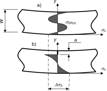
The CCM is a destructive technique and one of the most effective procedures used to determine the distribution of residual stresses in a material. It allows to obtain the distribution of the residual stresses acting in a material as well as the stress intensity factor that results from introducing cracks. In fact, the principle of the CCM is the one that calculates the stresses from the stress intensity factor rather than the other way around [7]. The method is based on the introduction of a crack or a cut into a body that contains residual stresses, with a slow increment of the cut length. Residual stresses are released at the newly created surfaces and cause the stress field to be rearranged in the entire body (Figure 2a). Based on the change of strain at a place due to the progressive cutting, starting at the rear surface (Figure 2b), it is possible to calculate the stress that acted along the corresponding axis x in the initial un-cracked state [6].
Compared to other destructive techniques, the CCM contributes with some unique capabilities for the determination of residual stresses. The technique is a relatively simple tool used to determine the stress intensity factor caused by a
crack in a residual stress field and provides the means to measure crack closure stresses. This technique can be fairly easily applied with commonly available equipment such as strain gauges and electric discharge or conventional machining. This offers increased spatial resolution of residual stresses and sensitivity to low stresses. The CCM can be applied to many distinctive materials including different metals, polymers and composites. Different geometrical tested configurations include surface and through thickness measurements, axial stresses in plates (beams and strips), axi-symmetric stress in cylindrical components, pre-cracked specimens, central holes, and others [8-11].
The analytical solution that uses the CCM can be carried out only if the relaxed strain readings have been obtained from cutting a component induced with residual stresses. In general, the analyses for the determination of the residual stresses from the collected strain data can be performed in two ways: through the forward solution approach or by the inverse solution method [5]. These solutions are based on linear elastic fracture mechanics or linear elastic and isotropic material consideration. The inverse solution developed and used in this work is explained as follows:
S
x yb) a
W
x y
ER(x)a)
Journal of Applied Research and Technology 159 Consider a 2D arbitrary body influence from the
effects of a crack of length and unknown residual stresses (Figure 3). By extending the crack a small increment a, the change in the surface strain M produced by the crack extension can be obtained by using strain gauges at an arbitrary point M [7]. The strain increment M can be expressed by means of Castigliano’s theorem as
U is the difference in the elastic energy stored before and after the extension of the crack, F is a virtual force acting tangentially to the surface at M, and s is the distance between arbitrary point M and the point of the application of line force F. The reaction forces F can be arbitrarily introduced. In most cases, the force is positioned at symmetrical locations with respect the point M (Figure 3). The difference in the elastic energy stored before and after the extension of the crack, in terms of the stress intensity factor, can be expressed as [12]
(2)
where E’ is the generalized Young’s modulus (E’ = E for plane stress condition and E’ = E / ( 1-2) for plane strain) and B is the thickness. At the crack tip, KIrs and KIIrs are the stress intensity factors due to the residual stress and KIF and KIIF are the stress intensity factors due to the virtual force. By inserting Equation 2 in Equation 1 and as KIF is a linear function of F and KIrs is independent of s [7]:
(3)
In this work, a system in which both KIIF and KIIrs vanish is considered (which is the case for symmetrical systems with respect to the crack plane and/or the situation in which forces F do not produce shearing stresses at the plane y = 0) [9]. Therefore:
It is possible to obtain the relationship between the strain change at the arbitrary point M and the stress intensity factor at incremental crack lengths from Equation 3a. It can be re-arranged to give Equation 4 [9].
y
s
a
F
x
a
s F
Gauge positioned at bottom (M) M
Figure 3. Mechanical system considered to establish the relationship between the stress intensity factor and the strain at an arbitrary point M [7]
(1)
Numerical and Experimental Analysis in the Manipulation of the Mechanical Properties for Enhancing the Mechanical Resistance of a Material,G. Urriolagoitia‐Sosa et al., 156‐172
Vol.9, August 2011 160
where Z(a) is a geometry dependent function that reflects the sensitivity of the strain at M with respect to stresses released at the crack tip and is given by Equation 5 [13].
Z(a) is called the influence function. By determining the change in the strain caused by the extension of the crack by da and substituting the (dM / da) as obtained in Equation 4, the stress intensity factor due to a crack in a residual stress field can be obtained, provided that Z(a) for the configuration is known. From this theory, it was possible to develop the global polynomial residual stress field inverse method [3]; considering a as a slot or cut of depth t and a unit thickness in a body (Figure 4) [14]. The surface traction y(x) is the unknown residual stress that has to be deduced from the measurement of strain at some location (for example x = 0, y = s or at x = t, y = 0) (Figure 4). Furthermore, let the unknown residual stress distribution in the beam be represented as a nth order polynomial series as [14]
where Ai are the coefficients that have to be obtained and Pi are a power series, x0, x1, x2, …. xn etc., their Legendre polynomials are also used. However, the CCM includes a step which assumes that a stress distribution, y(x) = Pi(x), interacting with the crack is known. This known stress field is used to obtain the crack compliance function C by using Castigliano’s approach. To illustrate the determination of the compliance functions, a strip of unit thickness and unit width in the z direction with an edge crack of length a (Figure 5), is taken. In order to obtain the horizontal displacement u at (l, s), a pair of virtual forces F are introduced at that location in the horizontal direction.
The change in the strain energy due to the presence of the crack and the virtual force is [9]:
where KI is the stress intensity factor due to the known stress field, and KIF is the stress intensity factor due to the virtual force F. Applying Castigliano’s theorem, the displacement u(a,s) can be determined by taking a derivative of the strain energy with respect to the virtual force, as [14]
(8)
y
a
x
y(x) = Ai Pi(x) ni = 0
t
Figure 4. Edge-Cracked strip subjected to surface loading and virtual force [9].
(4)
(5)
(6)
Journal of Applied Research and Technology 161 Differentiating now with respect to distance s, the
strain in the x-direction is given by Equation 9 [14]:
Strain ε (a,s), due to stress Pi(x), is known as
the compliance function Ci(a,s) so that
(9a)
Due to linearity of KIF with F, the second term under the integral sign in Equation 9a is the same as Z(a) in Equation 5 with B = 1; therefore, it can be written as
(9b)
By following the approach in Schindler et. al. [9] and Kang et. al. [15] for the case of a beam with a strain measurement point M at the base (Figure 5), KI(a) and Z(a) can be expressed as
(9d)
where y(x) = Pi(x) and h(x,a) is known as the weight function. Once Ci(a,s) solutions have been obtained, the expected strain, due to the stress components in Equation 6, can be calculated as [14]
The unknown terms Ai have to be determined so that the strains given by Equation 10 match those from the strains measured in the experiment during cutting (aj,s)actual. To minimize the average error for all the data points for the nth order approximation, the method of least squares is used to obtain values Ai; therefore, the number of cutting increments m is often chosen to be greater than the order of polynomials Pi i.e. m n. Typically, m
= n + 1 is used [14]. In this work, n = 8 and m = 9 are used. The least square solution is obtained by minimizing the square of the error relative to the unknown constant Ai, i.e. as in Equation 10 [14]:
(11)
a
x
l
s s
y
(F,u)
Pi(x)
M
(F,u)
Figure 5. Measurement of strains near the cut or on the back face [14].
(9)
(9c)
Numerical and Experimental Analysis in the Manipulation of the Mechanical Properties for Enhancing the Mechanical Resistance of a Material,G. Urriolagoitia‐Sosa et al., 156‐172
Vol.9, August 2011 162
This gives
where [H] = [C]T[C] and {J}=[C]T{j}actual [21]. Equation 12 gives a simple set of simultaneous linear equations. For the problems considered in this work, [H] is an 8x8 matrix. The numerical procedure was implemented in a FORTRAN program using the Compact Visual FORTRAN package and Equation 9a was solved using the LU Decompositor (LUDCMP) and Backsubstitution (LUBKSB) routines [16]. The actual residual stress distribution was then determined by using Equation 6.
3. Material selection, specimen instrumentation and metal characterization
The material selected to perform this research was AISI 316L stainless steel which is one of the most used for the manufacturing of prosthesis, in particular, the hip joint prosthesis (acetabulum and femoral head) [17]. Beam geometry was selected to manufacture 26 specimens (200 mm long, 10 mm high and 6.35 mm thick). A stress relief annealing heat treatment procedure was applied to all the specimens. The annealing process was performed in a controlled environment furnace, at 600 oC for half an hour and letting the material to slowly cool down inside the chamber of the furnace [18].
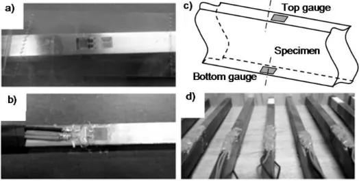
Once the annealing process was concluded, all the specimens were instrumented with strain gauges (Figure 6a and 6b) [19]. Two strain gauges were laid down, at the top and bottom surface, respectively (Figure 6c). The strain gauges will provide the necessary data to characterize the material under a bending test. Also the gauges will provide the results from the strain hardening procedure and the strain relaxation information needed to apply the CCM. Additionally, the strain gauges on the specimens used for the determination of the effect of strain hardening and/or the induction of bending residual stress field by the CCM were sealed with a high tear strength silicon rubber and a nitrile rubber coating (Figure 6d).
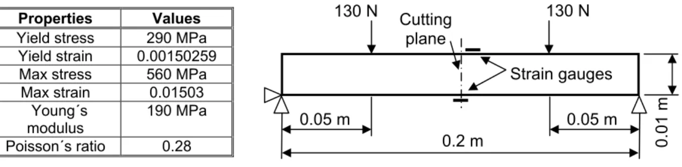
The mechanical characterization of the AISI 316L stainless steel was done with a four-point bending test using three beam specimens [20]. The bending strain results and the obtain stress-strain curve for this material are presented in Figure 7. The main advantage of this procedure is the simultaneous evaluation of tensile and compressive behavior. Furthermore, by applying the bending procedure, the previous loading history in the material can be determined. The Young´s modulus and Poisson´s ratio obtained from these tests were 190 GPa and 0.28, respectively, and were used for the application of the CCM.
Figure 6. Specimen implementation a) Strain gauge placed down. b) Concluded preparation of the application of the strain gauges. c) Final position of top and
bottom strain gauges. d) Sealed strain gauges.
Journal of Applied Research and Technology 163 4. Numerical simulation and analysis
Before the experimental procedure was carried out, the numerical analyses were developed. The finite element analysis (FEA) provides useful information and applicable guidance for the experimental procedure. The FEA presented in this paper is based on a four-point bending test. However, before applying the bending load that will introduce a residual stress field into the material, two cases with strain hardening will be considered
in which an specimen is axially pulled up to introduce a previous loading history. The strain hardening effect was induced by elongating the specimen by an amount of 0.000901554 m and 0.002103626 m. These values correspond to 3y and 7y of the material, which will produce strain hardening at two different levels. The geometry size of the specimen and mechanical properties used for the numerical simulation are shown in Figure 8. Also, the four-point bending configuration used to introduce a residual stress field is shown.
b)
Stress-Strain curve 600
450 300 150
0 6000 12000 18000 24000 Strain ()
S
tre
ss
(MPa
)
a)
Tensile curve Compressive curve 80
60 40 20
0 0.002 0.006 0.01 Strain ()
Mome
nt
(
N
m)
Figure 7. Mechanical characterization of AISI 316L stainless steel. a) Bending test data used to obtain the stress-strain curve. b) AISI 316L stress-strain curve.
Properties Values Yield stress 290 MPa
Yield strain 0.00150259 Max stress 560 MPa
Max strain 0.01503 Young´s
modulus
190 MPa Poisson´s ratio 0.28
0.05 m 0.05 m
0.2 m Cutting
plane
Strain gauges
130 N 130 N
0.01 m
Numerical and Experimental Analysis in the Manipulation of the Mechanical Properties for Enhancing the Mechanical Resistance of a Material,G. Urriolagoitia‐Sosa et al., 156‐172
Vol.9, August 2011 164
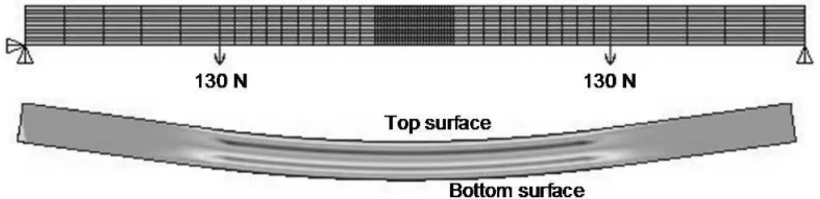
The numerical simulation was performed by the FEM commercial software. A Plane 183 element and a kinematic hardening rule were applied. Plane stress analysis was carried out and the mesh was defined in a controlled manner (Figure 9). In the center of the beam, a fine mesh was generated by elements of 1 mm high and 0.5 mm width. This was later used to simulate the introduction of the slot and evaluate the CCM. The residual stress field produced by a 130 N load is also illustrated.
4.1 1st Numerical case of study (specimen strain hardened at 3
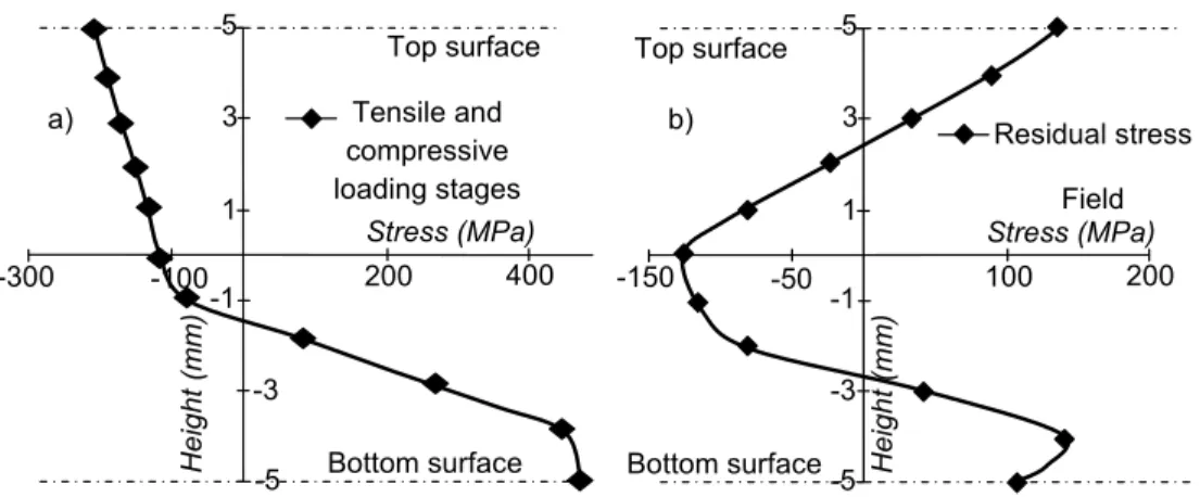
y)The residual stress field introduced by a bending procedure tends to have an axisymmetric shape [21-22]. The residual stress field can be manipulated by previously applying an axial pulling. Consequently, the residual stress field will lose its axisymmetric shape. In this case, the specimen was elongated 0.000901554 m
Figure 9. FEA configuration and residual stress field induction.
a)
Tensile and compressive loading stages 5
3
1
-1
-3
-5
Height (mm
)
Stress (MPa)
-300 -100 200 400
Top surface
Bottom surface
b)
Residual stress field 5
3
1
-1
-3
-5
Height (m
m)
Stress (MPa)
-100 -50 100 200
Top surface
Bottom surface
Figure 10. Numerical simulation for specimen pre-pulled at 3y. a) Tensile and
Journal of Applied Research and Technology 165 (equivalent to 3y), before the bending moment
was applied. The loading stage and the induced residual stress are shown in Figure 10.
4.2. 2nd Numerical case of study (specimen strain hardened at 7y)
In this case, the previous procedure is repeated; however, a change in the axial pulling will be set so as to produce an elongation of 0.002103626 m (equivalent to 7y). The loading stage and induced residual stress can be seen in Figure 11.
4.3. Numerical evaluation of the CCM
After the numerical simulation of the residual stress field induction was finished, the numerical
evaluation of the CCM was carried out. The evaluation of the CCM was performed by simulating the introduction of a slot into the beam (deleting elements at the central part, Figure 12), which will cause a modification by auto-equilibrium of the residual stress on the acting base line, producing a relaxation in the material [11].
The introduction of the slot will produce strain relaxation data that will be collected at the rear node of the cutting plain and could be used by the CCM to determine the original residual stress field. The residual stress field determined by the CCM for each one of these cases is presented in Figures 13a and 13b; the results for the numerical simulation are shown too.
Figure 11. Numerical simulation for specimen pre-pulled at 7y.
a) Tensile and compressive loading stages. b) Induced residual stress field.
b)
Residual stress
Field 5
3
1
-1
-3
-5 Heigh
t (mm)
Stress (MPa)
-150 -50 100 200
Top surface
Bottom surface
a) Tensile and
compressive loading stages 5
3
1
-1
-3
-5
Height (m
m)
Stress (MPa)
-300 -100 200 400
Top surface
Bottom surface
Figure 12. Numerical simulation of the slot into the beam.
Elements to be deleted in pairs by incremental steps to simulate the introduction of the slot
y
0.5
0.5
Node use to obtain the relaxed strain data Discretization of the beam
Top surface
Numerical and Experimental Analysis in the Manipulation of the Mechanical Properties for Enhancing the Mechanical Resistance of a Material,G. Urriolagoitia‐Sosa et al., 156‐172
Vol.9, August 2011 166
5. Experimental analysis
From the numerical evaluation, it can be noticed that the axial pre-pulling causes a detrimental introduction of a residual stress by bending. This was corroborated by pre-pulling and bending 6 specimens (3 were pre-pulled at 3y and 3 at 7y) and applying the CCM to determine the induced residual stress fields in each specimen. The results were similar to the ones obtained by FEA [23]. Consequently, it was decided to invert the strain hardening condition by an axial pre-compressed condition which, in theory, would increase the value of the yield stress in compression and produce a Bauschinger effect in tension.
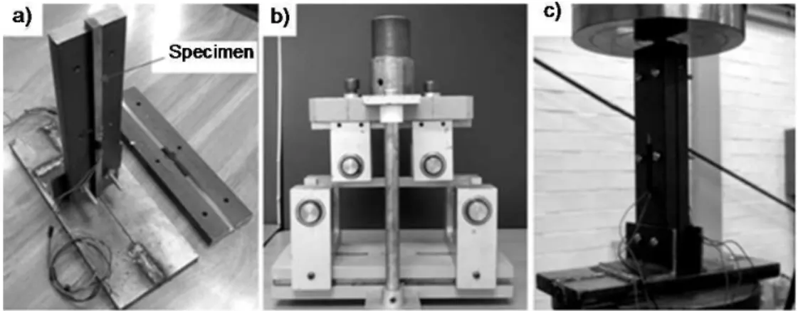
A batch of 12 annealed specimens were prepared with strain gauges (Figure 6c) and strain hardening condition was introduced by compression. For this task, it was necessary to develop a mechanical device that would allow the specimen to remain straight (at certain level). The axial compressive load was then applied (Figure 14a). A mechanical device is used to encapsulate the specimen, preventing bending and inducing the expected strain hardening condition into the material. The 12 specimens were divided into two groups and were compressed at 0.000901554 m and 0.002103626 m (equivalent to 3y and 7y, respectively).
Figure 13. Residual stress field induced in specimen pre-pulled. a) 3y pre-pulled specimen. b) 7y pre-pulled specimen.
a) FEA Results
5
3
1
-1
-3
-5
H
e
ight (m
m)
Stress (MPa)
-100 -50 100 200
Top surface
Bottom surface CCM Results
b)
FEA Results 5
3
1
-1
-3
-5 Height (mm
)
Stress (MPa)
-150 -50 100 200
Top surface
Bottom surface
CCM Results
Journal of Applied Research and Technology 167 Once the specimens were strain hardened by a
homogeneous load (Figure 14c), a four-point bending rig (Figure 14b) was used to plastically bend the specimens. From the bending procedure, it is possible to mechanically evaluate the new conditions in the material [20] (6 specimens were used, 3 specimens compressed at 3y and 3 specimens at 7y) and a residual stress field will be also induced into the material. The mechanical properties for these new conditions (before applying the bending procedure to introduce the residual
stress field) are presented in Figure 15. It can be clearly observed that strain hardening and a Bauschinger effect have been introduced into the material.
The application of the CCM has to be implemented by the introduction of an incremental slot. The cutting of the component has to be performed by a machining process that does not alter the original state of the residual stress field. In this sense, a plate electric discharge machine was chosen to introduce the slot and to relax the residual stress field (Figure 16).
Figure 15. Mechanical characterization of stainless steel AISI 316L.
a) Material pre-compressed axially to 3
yy. b) Material pre-compressed axially to 7
y.Tensile curve b)
700
525
350
175
0
500 1000 1500
Strain ()
Stress (MPa)
Compression curve Tensile curve
a) 700
525
350
175
0 500 1000 1500
Strain ()
Stress (MPa)
Compression curve
Numerical and Experimental Analysis in the Manipulation of the Mechanical Properties for Enhancing the Mechanical Resistance of a Material,G. Urriolagoitia‐Sosa et al., 156‐172
Vol.9, August 2011 168
The specimens are cut in successive steps (1mm depth by 1 mm width). As the heights of the beams are 10 mm, 9 consecutive cutting steps are performed and the beams are finally left with 1 mm of material to preserve the structural integrity. After each cutting step was performed, the strain relaxation caused by the reestablishing of the residual stress field, in what was left of the material, was collected as deformation by the strain gauge. The strain relaxation was utilized by the CCM and the original residual stress field inside the beam could be estimated. In Figure 17, the residual stress fields obtained for every condition in the material (pre-compressed (3y y and 7y) and bend) by the CCM are presented. Additionally, the figures present a comparison between the experimental procedures against both numerical simulations. 6. Discussions
This paper presents a methodology to manipulate the mechanical properties of a biocompatible material to enhance its mechanical resistance. The advantages of inducing the effect of strain hardening into a material have been fully established in specialized literature around the world; the beneficial aspects of introducing a residual stress field are also well documented. However, the application of both conditions has not been completely investigated. This paper demonstrates that the conjunction of strain
hardening and residual stresses could develop a detrimental effect on the material. Additionally, a numerical simulation has been performed in this research to determine the possible effects of strain hardening and the introduction of a residual stress field in order to enhance the implementation of the experimental analysis. By achieving FEA, it was possible to determine what to expect when these two mechanical conditions are applied. On the other hand, FEA has been useful to evaluate the accuracy of the CCM and could provide vital information for the experimental application of the CCM. The CCM has gradually consolidated in the engineering area as a very good method for evaluating and determining residual stresses. It is a very simple technique to be applied, low in cost, easy to implement, reasonably accurate and has drawn good attention from the scientist community. Nonetheless, the CCM needs to be numerically and experimentally evaluated in a major and diverse manner with the purpose of extending its application to spread its use and to ensure its acceptance by the scientific community.
7. Conclusions
This paper has analyzed the way in which the application of strain hardening and the induction of a residual stress field can decrease the mechanical resistance of a material. It is apparent that the substantial beneficial effect that causes the
Figure 17. Residual stress fields in specimens made from stainless steel AISI 316L. a) Material pre-compressed axially to 3y. b) Material pre-compressed axially to 7y.
Tensile curve b)
700 525
350
175
0 500 1000 1500 Strain ()
Stress (MPa)
Compression curve Tensile curve
a) 700
525
350
175
0 500 1000 1500 Strain ()
Stress (MPa)
Journal of Applied Research and Technology 169 application of a strain hardening process or the
induction of a residual stress by themselves can be recognized. However, this research corroborates that the introduction of both beneficial effects could cause a decrease of the mechanical resistance of the material. From Figures 10b and 11b, it can be observed that the bending introduction of a residual stress will tend to be detrimental to the component if the material has been axially pulled, because a high tensile residual stress field will be left on the surfaces of the material. This tension stress will lead to consider the surface layer in a tensile state, which has to be added to the action of the tensile external agent. This existing residual stress acting on the surface will be predisposed to encourage the tensile action and could activate the nucleation or propagation of defect. In this matter, it is not important how the hardening process raise the yield tensile strength of the material, what it is important to determine is the Bauschinger effect and the compression behavior of the material. The Bauschinger effect on the compressive side is important because the yield compressive stress has decreased (Figure 10a and 10b) in comparison with the tensile side; theory states that non-homogeneous elasto-plastically loading on the surface of the material in a particular direction will be transformed in the opposite stress direction in the same when the residual stress is induced. Nevertheless, it could be even worst (Figure 11b). There is a possibility that both surfaces can be left with a detrimental residual stress field.
The numerical simulation has provided sufficient data to perform the experimental analysis. The experimental procedure has been done to enhance the mechanical resistance of the material by inducing a compressive strain hardening and introducing a beneficial residual stress field. In Figures 17a and 17b, it can be observed that the surfaces of the beams tend to be in compression, which propitiates a tensile external agent to overcome this compressive stress before the damage to the material starts. This is important because components obtained from material fabricated by extraction and bending could have a predisposition to be weak and, in the worst scenery, to fail.
Additionally, in this research, the CCM was numerically and experimentally evaluated. By the application of the numerical analysis, it was
possible to simplify the experimental implementation, reducing time and cost. Also, FEA has proved to be an important tool, which provides information about what to expect when performing experimental application. At present, there is a great quantity of information about the experimental application of the CCM and its assessment. In this regard, the authors state that there is insufficient information about the correct manner of performing the experimental procedure to be convinced that the results obtained are the optimum ones. It is considered that FEA could be the best option for evaluating the CCM and could bring more specific information on the best way to use it. The experimental implementation of the CCM has brought results that are similar to those obtained by numerical simulations and has encouraged authors to continue with their research in this field of engineering.
References
[1] Urriolagoitia-Sosa, G., Analysis of prior strain history effect on mechanical properties and residual stresses in beams, Oxford Brookes University Ph D Thesis, 2005
[2] Cheng, W. and Finnie, I., Residual stress measurement and the slitting method, Ed. Springer, 2007, pp. 2-4
[3] Cheng, W. and Finnie, I., The crack compliance method for residual stresses measurements, Welding in the World, Vol. 28, 1990, pp. 103-110
[4] Cheng, W. and Finnie, I., A new method of measurement of residual axial stresses applied to a multi-pass but welded cylinder, Journal of Engineering Materials Technology, Vol. 109, 1987, pp. 337-342
[5] Prime, M. B., Residual stress measurement by successive extension of the slot: The crack compliance method, Applied Mechanics Review, Vol. 52, No. 2, 1999, pp. 75-96
[6] Schindler, H. J., Determination of residual stress distribution from measured stress intensity factors, International Journal of Fracture, Vol. 74, No. 2, 1995, pp. 23-30
Numerical and Experimental Analysis in the Manipulation of the Mechanical Properties for Enhancing the Mechanical Resistance of a Material,G. Urriolagoitia‐Sosa et al., 156‐172
Vol.9, August 2011 170
Conference on Residual Stresses (ECRS4), Cluny, France, 1997, pp. 509-517
[8] Cheng, W. and Finnie, I., Measurement of residual hoop stresses in cylinders using the compliance method, ASME Journal of Engineering Materials and Technology, Vol. 108, 1986, pp. 87-92
[9] Schindler, H. J., Cheng, W. and Finnie, I., Measurement of the residual stress distribution in a disk or cylinder using the crack compliance method, Proc. 4th Int. Conf. Residual Stress, Baltimore, MD, 1994, pp. 1266-1274
[10] Cheng, W., Finnie, I. and Vardar, O., Estimation of axisymmetric residual stress in a long cylinder, ASME Journal of Engineering Materials and Technology, Vol. 114, 1992, pp. 137–140
[11] Urriolagoitia-Sosa, G., Durodola, J. F. and Fellows, N. A., Determination of residual stress relaxation by the use of the crack compliance method, Proceedings of the 14th International Materials Research Congress, IMRC 2005, Cancún, México, 2005, pp. 35
[12] Irwin, G. R., Analysis of stresses and strains near the end of a crack traversing a plate, Journal of Applied Mechanics, Vol. 24, 1957, pp. 361-363
[13] Schindler, H. J. and Bertschinger, P., Some steps towards automation of the crack compliance method to measure residual stress distribution, 5th Int. Conf. Residual Stress, Linköping, Sweden, 1997, pp. 682-687
[14] Cheng, W. and Finnie, I., An overview of the crack compliance method for residual stress measurement, Proc. 4th Int. Conf. Residual Stress, Baltimore, MD, Society for Experimental Mechanics, 1994, pp. 449-458
[15] Kang, K. J., Song, J. H. and Earmme, Y. Y., A method for the measurement of residual stresses using a fracture mechanics approach, Journal of Strain Analysis, Vol. 24, 1989, pp. 23-30
[16] Press, W. H., Flannery, B. P., Teukolsky, S. A. and Vetterling, W. T., Numerical recipes, Ed. Cambridge University Press, 1987
[17] Dowling, J. M., Atkidson, J. R., Dowson, D. and Charnley, J., The characteristics of acetabular cups worn in the human body, The Journal of Bone and Join Surgery, Vol. 60-B, No. 3, 1978, pp. 375-382
[18] Chandlers, H., Heat treater’s guide practice and procedures for Irons and Steels, 2nd Edition, ASM International, 1995
[19] Measurements group, Student manual for strain gauge technology, Bulletin 309D, 1992, pp. 17-23
[20] Urriolagoitia-Sosa, G., Durodola, J. F. and Fellows, N. A., A method for the simultaneous derivation of tensile and compression behaviour of material under Bauschinger effect using bend tests, Proceedings of the Inst. of Mech. Eng., Part C, J. of Mech. Eng. Sci., Vol. 220, No. 10, 2006, pp. 1509-1518
[21] Urriolagoitia-Sosa, G., Durodola, J. F. and Fellows, N. A., Determination of residual stress in beams under Bauschinger effect using surface strain measurements, Strain, Vol. 39, No. 4, 2003, pp. 177-185
[22] Urriolagoitia-Sosa, G., Durodola, J. F. and Fellows, N. A., Effect of strain hardening on residual stress distribution in beams determined using the crack compliance method, Journal of Strain Analysis for Engineering Design, Vol. 42, No. 2, 2007, pp. 115-121
[23] Molina-Ballinas, A., Numerical-experimental strain hardening evaluation and determination of the consequences of Bauschinger effect in the mechanical properties of a stainless steel, M Sc Thesis, Instituto Politécnico Nacional, SEPI ESIME, 2010, pp. 75-105.
Acknowledgements
The authors gratefully acknowledge the financial support from the Mexican government through Consejo Nacional de Ciencia y Tecnología (The National Council on Science and Technology), CONACYT, and the Instituto Politécnico Nacional (National Polytechnic Institute), IPN.
Journal of Applied Research and Technology 171
Authors´ Biographies
Guillermo URRIOLAGOITIA-SOSA
Dr. Urriolagoitia-Sosa got his PhD degree from Oxford Brookes University in 2005, an MSc degree from the University of Oxford in 2000 and an MSc degree from SEPI ESIME, Instituto Politécnico Nacional (National Polytechnic Institute), IPN, in 1997. He has been a member of the Sistema Nacional de Investigadores (National System of Researchers) since 2006 and was a research assistant at the University of Oxford and Oxford Brookes University from 1999 until 2005. Additionally, Dr. Urriolagoitia-Sosa has served as a reviewer for several International journals and as a director of more than 6 research projects economically supported by IPN.
Arafat MOLINA-BALLINAS
He received his MSc degree from SEPI ESIME-Azcapotzalco, Instituto Politécnico Nacional, in 2010. Currently, he is a PhD student at SEPI ESIME-Zacatenco of Instituto Politécnico Nacional and will obtain the PhD degree by 2013. His research topic is the determination, analysis and quantification of residual stress in manufactured parts. He was the 2nd place winner of the award of Engineering Mexico City 2010 in the category “Graduate or Postgraduate student in the field of mechanical engineering”. He was a reviewer judge in the ASME Student Section event at Instituto Tecnológico y de Estudios Superiores de Monterrey (Technological Institute of Higher Education of Monterrey), Campus Mexico City in April 2011. He has published 2 papers in journals and participated in several conferences such as CIBIM 2009, IMRC 2009-2010, IAS 2010, Congreso Científico-Tecnológico de la Carrera de Ingeniería Mecánica Eléctrica (Scientific Technological Conference of the Electrical Mechanical Engineering Major), FES Cuautitlán (UNAM) from 2009 to 2010, Congreso Internacional sobre la Enseñanza de las Matemáticas 2011 (International Conference on Mathematics Teaching 2011), RIIM 2011, BSSM 2011, WCE 2011.
Guillermo URRIOLAGOITIA-CALDERÓN
Dr. Urriolagoitia-Calderón received his PhD degree from Imperial College of Science and Technology, London, in 1976 and his MSc degree from the University of Strathclyde, Glasgow in 1970. He has been a member of the Sistema Nacional de Investigadores since 1998. He was the Head of the Division of Postgraduate Studies at IPN from 1985 to 1988 and Head of SEPI ESIME-Zacatenco from 1995 to 1998. From 2000 to date, Dr. Urriolagoitia-Calderón has been Chief Editor of the Journal CIENTIFICA. Finally, he has served as a reviewer for several International journals and director of more than 25 research projects economically supported by CONACYT and IPN.
Numerical and Experimental Analysis in the Manipulation of the Mechanical Properties for Enhancing the Mechanical Resistance of a Material,G. Urriolagoitia‐Sosa et al., 156‐172
Vol.9, August 2011 172
Luis Héctor HERNÁNDEZ-GÓMEZ
Dr. Hernández-Gómez got his D. Phil, degree from University of Oxford in 1992 and his MSc degree from SEPI ESIME-Zacatenco, Instituto Politécnico Nacional, in 1985. He has been a member of the Sistema Nacional de Investigadores since 1986. Dr. Hernández-Gómez is also a member of ASME and Academia Mexicana de Ciencias (Mexican Academy of Sciences). Finally, he has been director of more than 20 research projects economically supported by CONACYT and IPN.
Beatriz ROMERO-ÁNGELES
She received both her BSc and Msc degrees from SEPI ESIME-Zacatenco, Instituto Politécnico Nacional. Currently, she is a PhD student at SEPI ESIME-Zacatenco of Instituto Politécnico Nacional and will obtain the PhD degree by 2013. Also, she has been part of the research staff of the ESIME-Azcapotzalco since 1990 and has collaborated on four research projects economically supported by CONACyT and IPN. It has graduate more than 15 engineers. It has participated in than 50 International and National Conferences and published more 8 papers in international journals. Winner of the second place prize 2010 of the Engineering of the Mexico City completion and best graduate performance student of 2010 by the IPN.
Alexandre MICHTCHENKO
Graduated from Moscow Institute of Physics and Technology/MFTI/, M. Sc. 1977 and Ph D 1980. Research staff in the N.N.Semenov’s Institute of Chemical Physics from 1981 to 1998, Moscow, Russia. Invited Professor in the Chemistry Institute of Universidad Nacional Autónoma de México from 1992-1998. Research staff in Instituto Politécnico Nacional of Mexico from 1998 until now. Investigations in the field of lasers and their applications in technology. Included in the book “Who’s who in the world” in 2010, 2011.
![Figure 1. Electric discharge machining used to apply the CCM [1].](https://thumb-eu.123doks.com/thumbv2/123dok_br/18414907.360218/2.918.266.638.667.970/figure-electric-discharge-machining-used-apply-ccm.webp)
![Figure 3. Mechanical system considered to establish the relationship between the stress intensity factor and the strain at an arbitrary point M [7]](https://thumb-eu.123doks.com/thumbv2/123dok_br/18414907.360218/4.918.506.776.294.379/figure-mechanical-considered-establish-relationship-stress-intensity-arbitrary.webp)
![Figure 4. Edge-Cracked strip subjected to surface loading and virtual force [9].](https://thumb-eu.123doks.com/thumbv2/123dok_br/18414907.360218/5.918.148.778.626.999/figure-edge-cracked-strip-subjected-surface-loading-virtual.webp)
![Figure 5. Measurement of strains near the cut or on the back face [14].](https://thumb-eu.123doks.com/thumbv2/123dok_br/18414907.360218/6.918.137.798.582.997/figure-measurement-strains-near-cut-face.webp)