Hugo Delgado
Licenciatura Engenharia Informática
Characterization and Surface Reconstruction
of Objects in Tomographic Images of
Composite Materials
Dissertação para obtenção do Grau de Mestre em Engenharia Informática
Orientador :
Pedro Medeiros, Professor Associado, Faculdade de
Ciências e Tecnologia da UNL - Dep. de Informática
Júri:
Presidente: Ana Maria Dinis Moreira, Prof. Associada, Faculdade de Ciências e Tecnologia da UNL - Dep. de Informática
Arguentes:
Vogais: José Manuel Fonseca, Professor Auxiliar, Faculdade de Ciências e Tecnologia da UNL - Dep. de Eng. Electrótecnica
iii
Characterization and Surface Reconstruction of Objects in Tomographic Im-ages of Composite Materials
Copyright cHugo Delgado, Faculdade de Ciências e Tecnologia, Universidade Nova de Lisboa
Abstract
In the scope of the project Tomo-GPU supported by FCT / MCTES the aim is to build an interactive graphical environment that allows a Materials specialist to define their own programs for analysis of 3D tomographic images. This project aims to build a tool to characterize and investigate the identified objects, where the user can define search criteria such as size, orientation, bounding boxes, among others. All this processing will be done on a desktop computer equipped with a graphics card with some processing power.
On the proposed solution the modules for characterizing objects, received from the identification phase, will be implemented using some existing software libraries, most notably the CGAL library. The characterization modules with bigger execution times will be implemented using OpenCL and GPUs. With this work the characterization and reconstruction of objects and their research can now be done on conventional machines, using GPUs to accelerate the most time-consuming computations. After the conclusion of this thesis, new tools that will help to improve the current development cycle of new materials will be available for Materials Science specialists.
Resumo
No âmbito do projecto Tomo-GPU financiado pela FCT/MCTES o tema central é a construção de um ambiente gráfico interactivo que permita a um especialista de Mate-riais definir os seus próprios programas para análise de imagens tomográficas 3D. Com este projecto pretende-se construir uma ferramenta que permita caracterizar e pesquisar os objectos identificados, podendo o utilizador definir critérios de pesquisa tais como dimensões, orientação, factores de forma, entre outros. Todo este processamento será feito num computador desktop equipado com uma placa gráfica com algum poder de processamento.
O processo de caracterização e reconstrução dos objectos é um processo computacio-nalmente dispendioso e que actualmente o seu tempo de processamento deixa os cientis-tas mais limitados na analise destes objectos. Ter a possibilidade de poder executar toda a computação num computador economicamente acessível, e de uma forma mais rápida do que actualmente se faz, traz bastantes vantagens. Alguns dos temas a abordar têm a ver com a utilização de bases de dados em memória, outro aspecto que poderá vir a ser explorado é a utilização de GPGPUs, para o processo de caracterização dos objectos.
A solução proposta passa por implementar módulos de caracterização de objectos provenientes da fase de identificação com recurso a algumas bibliotecas aplicacionais existentes, mais nomeadamente a biblioteca CGAL. Serão também implementados, com recurso a GPUs e OpenCL, os processos de caracterização e reconstrução que tenham tempos de execução mais longos. Com este trabalho a caracterização de objectos e a sua pesquisa pode passar a ser feita em máquinas convencionais, com recurso a GPUs para acelerar as computações mais morosas. Desta forma é fornecida aos especialistas de materiais mais uma nova ferramenta que vem ajudar a melhorar o actual ciclo de desenvolvimento de novos materiais.
Contents
1 Background 1
1.1 Context . . . 1
1.1.1 Tomo-GPU Project . . . 2
1.1.2 SCIRun . . . 4
1.2 Problem . . . 5
1.2.1 Characterizations Data Persistency . . . 6
1.2.2 Object Reconstruction Filter . . . 6
1.3 Approach. . . 6
1.3.1 Characterizations Data Persistency . . . 7
1.3.2 Object Reconstruction Filter . . . 7
1.3.3 Parallelization . . . 8
1.3.4 SCIRun Integration . . . 8
1.4 Thesis Contributions . . . 8
1.5 Thesis Organization. . . 9
2 Object Characterization 11 2.1 Problem . . . 11
2.2 Relevant Work . . . 12
2.2.1 Computacional Geometry . . . 12
2.2.2 Data Persistency . . . 20
2.2.3 Reducing Execution Time using Available Cores . . . 22
2.3 Solution Organization . . . 24
2.3.1 Organization . . . 24
2.3.2 Storage . . . 26
2.4 Implementation . . . 27
2.4.1 PCA . . . 28
2.4.2 Bounding Boxes. . . 28
xii CONTENTS
2.4.4 Tests . . . 30
2.5 SCIRun Integration . . . 30
2.5.1 How to turn the standalone code in a SCIRun module . . . 31
2.5.2 Module position in the TomoGPU software . . . 31
2.6 Parallelization . . . 31
2.6.1 Approach . . . 31
2.6.2 Conclusion . . . 34
2.7 Conclusion . . . 34
3 Object Reconstruction 35 3.1 Problem . . . 35
3.1.1 Problem Definition . . . 35
3.2 Relavant Work . . . 36
3.2.1 Computation Geometry . . . 36
3.2.2 Space Partitioning . . . 37
3.2.3 Implicit Surface Reconstruction Techniques . . . 38
3.2.4 Image Cleaning . . . 41
3.2.5 Software Libraries . . . 41
3.2.6 GPGPU Architectures . . . 42
3.2.7 Linear Algebra Libraries . . . 48
3.3 Proposed Solution . . . 48
3.3.1 Organization . . . 49
3.4 Implementation . . . 50
3.4.1 Remove Interior Voxels from Object . . . 51
3.4.2 Create Initial Triangulation . . . 51
3.4.3 Compute Surface Normals . . . 51
3.4.4 Poisson Reconstruction . . . 51
3.4.5 Extract Surface Mesh . . . 52
3.4.6 Tests . . . 52
3.5 SCIRun Integration . . . 52
3.6 Optimizing Solution . . . 53
3.6.1 A - Multi-Core Approach . . . 53
3.6.2 B - CPU-GPU Approach . . . 53
3.6.3 C - Meshing Algorithm Replacement . . . 54
3.7 Conclusion . . . 54
4 Conclusions 57 4.1 Work evaluation . . . 57
CONTENTS xiii
A Mathematical Foundations 65
A.1 Linear Algebra and Matrices. . . 65
A.1.1 System of Linear Equations and Matrices . . . 65
A.1.2 Eigenvalues and Eigenvectors . . . 66
A.1.3 Solving Systems of Linear Equations. . . 66
A.2 Statistics . . . 68
A.3 Geometric and Analytical Measures . . . 68
A.3.1 Mathematical Foundations . . . 68
A.3.2 Distance Metrics . . . 68
B SciRun Integration 71
1
Background
In this chapter, we start by describing the context of this work, followed by a description of the problem, approach and expected contributions of this dissertation.
1.1
Context
This work has two main focus, the first is to provide an extensible framework for the integration of geometric algorithms on some previously identified particles on datasets, providing data persistency of the computed geometrical measures. The second focus of this work relies with the reconstruction of the surface from incorrectly sampled particles on theTomo-GPUproject, offering an alternative solution to the currently available tech-niques used on the project. The techtech-niques that are currently employed cannot correctly reconstruct the shape on those bad particles and a different approach to the reconstruc-tion should be devised. This tools will be integrated on other project calledTomo-GPU
1. BACKGROUND 1.1. Context
Figure 1.1: Modules Position inTomo-GPUproject workflow.
1.1.1 Tomo-GPU Project
This project was founded by FCT/MCTES (PTDC/EIA-EIA/102579/2008 - Ambiente de Resolução de Problemas para Caracterização Estrutural de Materiais por Tomografia) and its main objective is the building of an environment that helps a Materials Science specialist to divide new composite materials, commonly know by composites, that are formed by combining materials together to form an overall structure that is better than the individual components. The idea is to obtain new materials for use in cars, planes, rockets, etc.. For testing new processes of building composite materials, tools for the characterization of the reinforcement population are needed; in the Tomo-GPU project the focus is on the analysis of tomographic images of composite materials.
The Tomo-GPU project have some important characteristics that drove the develop-ment of this thesis dissertation, and the most important characteristics of the Tomo-GPU environment are presented next:
Ease of use The environment allows the easy specification of a sequence of processing steps of the data.
Flexibility The integration of new capabilities in the system is easy.
Interactivity The processing steps have short execution times that promote an interac-tive use of the system, where users can change parameters of the processing and visualize.
Affordability The hardware and the software needed have prices that allow many re-search groups to use it.
Lets now see how this characteristics are obtained under the Tomo-GPU Project: Ease of use and flexibility are obtained by using a graphical tool to do the data
1. BACKGROUND 1.1. Context
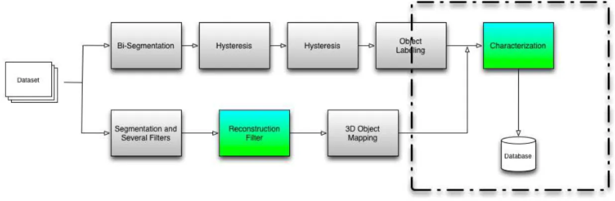
Figure 1.2: Overall view of Tomo-GPU modules [Ea12]
SCIRun[PJ95], as previously seen this modules could be added or removed from one workflow as needed.
Interactivity and affordability are achieved by targeting an hardware platform based on a desktop personal computer equipped with GPGPUs (General Purpose Graphic Processing Unit) [OLGHKLP07]. The use of the great computing power of this hardware platform allows fast execution times of highly-demanding processing al-gorithms - for example, 3D image processing - without expensive investments on hardware or access to remote clusters.
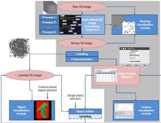
Figure 1.2 shows some of the modules that had been developed in the project and how they could be connected to produce an 3D tomographic image analysis pipeline, those modules can be divided in the following categories:
Defect removal 3D Image processing techniques are used to clean the image of artifacts that are originated by the method of image acquisition. The object is to have a monochromatic image where the matrix corresponds to white and objects are black.
Image labeling In the monochromatic image, sets of connected black voxels are identi-fied; each set receives a unique label.
1. BACKGROUND 1.1. Context
Object characterization From each individual object, some characteristics are extracted. In this phase, most of the characteristics are related with geometry - dimensions, bounding box, volume, area, etc..
Object characteristics mining A repository containing object characteristics of different samples is built. Tools for querying that database allow the Materials specialist to evaluate the process used in the creation of the sample.
In this dissertation the focus is at the object characterization and the object filtering categories, but we will also address the last category, object characteristics mining, al-though not as the primary goal but providing the tools so that functionality could be added when needed.
1.1.2 SCIRun
SCIRun is an open source project that was supported by grants from the National Center for Research Resources (5P41RR012553-14) and the National Institute of General Medical Sciences (8 P41 GM103545-14) from the National Institutes of Health[Ins13]. It is a com-putational workbench developed by the SCI group from from the University of Utah, its an open source licensing software and used worldwide in many universities and research
1. BACKGROUND 1.2. Problem
groups, mainly on the field of the biomedical investigation. As one can see on Figure1.3 this software is a tool for building the so-called problem solving environments (PSEs) that allows the construction of programs through a visual programming approach. In theSCIrunenvironment one has a menu with of several modules; each one of the mod-ules hasinput portsandoutput ports. The general idea is that each module produces, in one of its output ports, a modified version of the data that is received through one or more of its input ports.
For the graphical front endSCIRunuses theTcl/TK, and have anTCLInterfaceto pro-vide an abstraction layer that make the task of moving data between theTcland the C++ portions ofSCIRuntransparent to the user. On theTclside, the code access variables such as regular Tcl variables and on the C++ side the code needs to declare those variables under a module class and access them.
Being an open source software and its used worldwide brings some advantages such as having an active community where problems could be exposed. The available devel-oper manual isn’t very well documented and that introduce a learning curve before a developer could fully use the available features on the framework.
1.2
Problem
There are several problems addressed on our work, but mainly we will deal with the ge-ometric characterization and reconstruction of previously identified particles, that from now on we denote by objects. For now there is the need to have a tool for characterizing geometrically, with some defined characterizations, the objects and store the resulting values for latter access. But the number of characterizations that need to be stored could increase according to the needs of theTomo-GPUproject.
Under a different scope, in some specific datasets the resulting output from previous processing stages onTomo-GPU Projectpresented to be processed contains errors and the objects received may not be complete, so this tool should be able to deal with noise intro-duced either by the nature of the composite materials or accumulated over the previous processing stages.
1. BACKGROUND 1.3. Approach
1.2.1 Characterizations Data Persistency
There is the need to store the data from the characterizations for latter access, to fully understand the objects a sample should be processed several times producing several datasets to be analyzed, although they are analyzed on different workflows on theSCIRun. If the data between different ct-scans remains available, other tools may be built to query that data. With that capability one could easily search for specific features on several ob-jects among different samples. In order to do that there should be added support to store the results for later searching and should be easy to extend this data repository, in the case of different extraction methods are created and integrated on theSCIRun. Although not being the major goal from this work, this data should be structured in some way that could easily allow any scientist to latter access it, and fully infer about it.
1.2.2 Object Reconstruction Filter
TheTomo-GPUproject already contain some modules to extract the shape from an object. On some of the sampled materials the currently employed techniques didn’t behave cor-rectly and the extracted shape from the identified objects could contain holes or present some outliers, difficulting their accurate representation. None of the previous filter mod-ules on theTomo-GPU project could perform a good reconstruction mainly because the sparsity of the sampled points on the object surface. Under this scenario a different ap-proach to the reconstruction should be investigated so that the real shape from that ob-ject could be fully recovered, covering possible holes and removing the outliers. This implementation should be integrated onto theTomo-GPUproject, to latter be used on real samples.
1.3
Approach
In order to comply with the requisites for the project this work have been divided in two modules, one for the object characterization and other for the object reconstruction.
Although the main focus of this work is under the image analysis, this work started to study the availability to use in-memory databases and how they could be used in a
GPGPU environment, for storage and fast query of the characterization data returned from the characterization module, soon we saw that the amount of data and the required features for this project at this stage doesn’t require such techniques, and we choosed to introduce this data abstraction so latter if is found that such techniques could be used this modules could still be used for the object characterization.
1. BACKGROUND 1.3. Approach
1.3.1 Characterizations Data Persistency
The geometrical characterizations and the data persistency are ensured by a framework that can perform the desired goals. It is extensible in the sense that abstract the used database and easing the implementation of future characterizations by allowing to extend the current set of characterizations with new characterizations.
1.3.1.1 Characterizations Framework
Beside the capability of this module to perform the required computations it has been de-veloped as an module where some components may be plugged providing a framework for the characterization of the objects. These components are abstracted by a character-ization class and are made available to the user by aGUI component where one could choose which of the characterizations should be performed, this way it is easy to extend the system with new characterizations as they are needed.
This module have an graphical interface, allowing one to choose which of the char-acterizations should be computed, and at launch it will receive the objects and for each received object will compute the choosed geometric characterizations.
1.3.1.2 Data Layer Abstraction
In order to allow the characterized objects to be latter queried, these results will be stored in a repository, this repository should contain the different values from each characteri-zation from all objects, and although the small expected size for the characteristics repos-itory in terms of expected columns, this project as a part of a bigger project may grew in the number of characteristics to process, so it is to expect that the system should easily accommodate such changes. This is accomplished using an abstraction layer that will serve to interface different dbms systems throughSQL, allowing for further changes on the data layout easily. By storing the data using adbmswe gain expressiveness given by
SQLallowing a rich set of language to query the data, portability and persistency on the data are accomplished by the chooseddbms.
To provide the data persistency under the characterization module, we have intro-duced a data abstraction layer to abstract variousdbms’susingodbc, that way anydbms
that have a connectivity driver toodbccould be used to store the data for latter access, and that way portability is introduced to the data framework.
1.3.2 Object Reconstruction Filter
1. BACKGROUND 1.4. Thesis Contributions
is to reconstruct the surface based on inferring some properties at each point of the sur-face based on some local or global measures. We have chosen to use the poisson sursur-face reconstruction algorithm, that is an algorithm that tries to reconstruct the object surface according to global measures of the object voxels, it is highly resilient to data noise and is capable of perform an surface reconstruction with good detail. This process is suitable to errors since the original data also have errors and it isn’t complete, but it can infer the surface from those objects in a very accurate way, eliminating ghost voxels, and filling the holes of the objects on received input and with that approximate the real surface from that object.
This reconstruction phase won’t be used on all datasets, but only on those that one had previously identified as datasets containing noise. The data may come on in two different ways depending in the previous used filters on other stages of the Tomo-GPU
project, but mainly the data is composed of all the voxels from the object or only voxels that the previous algorithms have identified as surface voxels. To provide an easy to perform the reconstruction theGUI of the module allow to select if the interior voxels should be removed from the sampled object or not.
1.3.3 Parallelization
As interactivity is one of the keywords from this project, all the computations should be fast, and to accomplish this an assessment of the use of parallelization on the available hardware has been employed. On the characterization module, we have chosen to use multicore-cpu shared memory parallelization techniques such asOpenMPandPThreads, on the reconstruction module we have introduced parallelization using the gpu using
OpenCL.
1.3.4 SCIRun Integration
1.4
Thesis Contributions
The expected contributions of the thesis are:
A tool for object characterization A set of modules for extracting geometric character-istics of objects identified in tomographic images will be designed, implemented, assessed and integrated in the SCIRun environment. The execution times will be evaluated and versions for execution in GPGPUs will be developed. These versions will be compared with former ones regarding efficiency.
1. BACKGROUND 1.5. Thesis Organization
A repository of object characteristics Introducing a dbms as a repository system, and abstracting it from the development, will be the basis of what a consultant of the project called a "google of the particles".
The components above will enhance the functionality of the problem solving envi-ronment, making it more attractive to Materials Science specialists. Besides this con-tributions to the Tomo-GPU project, know-how about tools for geometric computing, in-memory databases and application parallelization will be obtained.
1.5
Thesis Organization
2
Object Characterization
In this chapter we start by introducing the problem, all the know-how and tools to per-form the required characterizations. After that is presented the proposed solution and implementation details, showing how the implemented framework work with the un-derlying databases and how it could be used on a multi-core shared memory architecture leveraging the previous implementation. We finish by introducing the integration onto theSCI-Runframework and showing the results from the implemented functionality.
2.1
Problem
Besides each received sample contains several objects, we start to look at the problem as the geometric analysis of one single object. Under this scope we have one object repre-sented as a setX ofnthree-dimensional unoriented pointsX ={x1, x2, ..., xn}, from all
2. OBJECTCHARACTERIZATION 2.2. Relevant Work
the voxels of the object including its interior and boundary. As seen, for this point set it should be computed its centroid, principal directions, object volume, object surface, axis aligned bounding box and the object oriented bounding box.
Each received object represent a previously identified particle on the ct-scan com-posed of several voxels. The ct-scan has been decomcom-posed on a regular grid in a three-dimensional space, and we receive all the voxels that belong to each identified object. We assume that the objects are compact, don’t have holes inside, all the voxels from the ob-ject are well sampled and that each voxel has another voxel connected to it. By connected voxel we have defined that each voxel has at least another voxel on one of its twenty six neighbor voxels.
The implemented framework besides computing the respective values for each char-acterization it should also store the resulting values on an underlying database for latter access. This framework ideally should be extensible by allowing an easy integration of other possible characterizations.
2.2
Relevant Work
Most of the presented algorithms rely upon mathematical or statistical models, where the analysis over the data is computed. We have compiled some mathematical concepts that are required to perform the characterizations and it can be found on AppendixA.
2.2.1 Computacional Geometry
For the given point setP, representing all points from an object in 3d-space where each point has the same density value, we start by introducing some mathematical concepts required to perform the required characterizations.
2.2.1.1 Geometric Characterization
Centroid One could think in the centroid in terms of physics, as the center of mass or barycenter, from an object. In geometry it is computed by the average of its geometric positions, and in some cases the centroid may not belong to the object.
¯ X=
Pn
i=1Xi
n
2. OBJECTCHARACTERIZATION 2.2. Relevant Work
Axis-Aligned Boundig-Box An axis-aligned bounding box orAABBis simply a rectan-gular parallelepiped whose faces are each perpendicular to the origin, here we want to figure the minimum axis-aligned parallelepiped that fully encloses all of the objet voxels, this is done by computing the minimum and maximum values on all three axis,x,yandz, that are given by two pointsPmin = (Xmin, Ymin, Zmin)andPmax= (Xmax, Ymax, Zmin).
Oriented Bounding Box This bounding box of the object can also be seen as minimum bounding rectangle that fully encloses an object. On this work we are only interested on the object-oriented bounding box as a simple bounding parallelepiped whose faces are parallel to the basis vectors representing the principal components obtained from PCA, as explained on2.2.1.1.
Volume There are analytical procedures to compute the volume from a solid, although in our case we are only interested in computing an approximate solution for the volume, that is simply given by the sum of the volume of each voxel from the object. Since our object is sampled on a regular spaced grid and each voxel have the same volume, the total volume is implicit defined by the number of voxels from the object. This is possible because each sample contains also some meta-information about each voxel spacing in regard to the real size of the sample.
Surface Area Since the sampled object represent a discretization of the real object under a regular grid there are different techniques that could be used to compute an approxi-mate value for the object surface area. One way is to reconstruct the surface from the object by a triangular mesh and compute the total area from the surface as the sum of all the areas of the triangles that compose the surface. Other simple process that may be applied on this specific case is to compute all the surface voxels from the input object and for each one of them compute the total area as the sum of the areas from all of the exposed faces from each voxel the surface, for that we defineΩ = {Ω1,Ω2, ...,Ωn′}as a subset of
X, representing all the voxels from the object that belongs to its surface. This definition is possible since the object is represented on a regular grid in athree-dimensionalspace and all the voxels have the same size and are equally spaced.
2. OBJECTCHARACTERIZATION 2.2. Relevant Work
To better understand this analysis one could look at it like a transformation on the objects to a new coordinate system such that the greatest variance comes to lie on its first principal component, the second greatest variance on the second principal component and so on.[APG12] So by this kind of analysis one will constrain each one of the vari-able in terms of the other two, and latter obtaining the values that minimize such new representation.
Principal Component Metodology In order to extract the principal component the next steps should be done:
1. Determine the centroid for X
2. Subtract the centroid to X, in order to center the data around its mean value
3. Compute the3×3covariance matrixM fromX 4. Compute the eigenvalues and the eigenvectors fromM
5. Order the eigenvalues and eigenvectors starting with the one with maximal eigen-value
2.2.1.2 Polygonization
Delaunay based Here at first it is constructed the Delaunay triangulation, or its dual1 voronoi diagram, partitioning the sample points into a finite set of tetrahedra, as presented on??its main advantages relies with its uniqueness. After the construc-tion of the triangulaconstruc-tion it is needed to figure out wich of the simplices belongs to the surface. There are a variety of proposed algorithms for constructing a Delaunay triangulation.
Region Growing It is a technique for solving geometric problems where an algorithm starts with a initial seed or complex of the final mesh and the solution is incre-mented by glueing other pieces to the initial seed and so on until the final mesh is constructed. Typically this kind of algorithms have complex strategies to deal with the intersections where the pieces of the mesh being added connect to the already constructed mesh to avoid the duplication of the final mesh.
Surface Splatting As presented on [ZPBG01], is a reconstruction technique that aims the direct rendering from point-based objects. They use a point-based algorithm, and provides a splat primitive that could be applied for large resolution laser scan ranges. Using a weighted sum of radially symmetric basis functions. It is also introduced an extension to Heckbert’s resampling theory to process point-based objects.
1
2. OBJECTCHARACTERIZATION 2.2. Relevant Work
Optimized Sub-Sampling Using an surface splatting technique the processing costs are still proportional to the number of primitives[ZPBG01] used to represent an object. This technique addresses specifically this problem, presenting a sub-sampling tech-nique for dense point clouds that are adjusted to the particular geometric properties of circular or elliptical surface splats.
Progressive Splat Generation This technique has been proposed for interactive ray-tracing of point-based models, that uses an full splat geometry estimating the error. They compute all the splats and after that they are ordered and an iterative algorithm that will progressively reach the number of desired splats and minimizing the global er-ror of the global reconstruction.
2.2.1.3 Convex Hull
It is by definition the smallest convex set that contains a finite point setP, it is also known by polytope. There is also a geometrical notation from the convex hull ofk+ 1points that are affinely independents calledk-simplex, a line segment for example is a 1-simplex, a triangle a 2-simplex and a tetrahedron a 3-simplex. In a d-dimensional space a facet from the convex hull are a (d-1)-simplice. There are known algorithms for incrementally compute the convex hull and their complexity in a 3-dimensional space is O(n log n), but can be improved by inserting the points in random order. [Cha93]
2.2.1.4 Voronoi Diagram
Their usage can be tracked back to Descartes in 1664 and its formal study and definition on a 2- and 3-dimensional space at 1850 by Dirichlet, latter the n-dimensional general space appeared at 1908 by a Ukrainian mathematician Georgy Fedosievych Voronyi. A Voronoi diagram or Dirichet tessellation is the division of a spaceMin a setSof seeds or sitessinM, in which exists a concept of influence that the region ofsexerts on a point xof M, where the region ofsconsists of all pointsx for which the influence ofsis the strongest, over alls ∈ S. There are several variants of this diagram depending upon different objects classes, distance functions and embedding space.
2.2.1.5 3D Triangulation
2. OBJECTCHARACTERIZATION 2.2. Relevant Work
a common measure the ensure the quality of the triangulation is the size of the internal angles from each tetrahedron that compose theT(P).
Delaunay Triangulation The Delaunay triangulationDT from a set of pointsS, from now on denoted byDT(S), is aT(S)that guarantees that no point,P ∈ S, is inside the circumscribed sphere of any tetrahedraT ∈ S. There are several algorithms proposed in the literature to compute the Delaunay triangulation such as incremental construction, divide and conquer and sweeping.
Other Triangulations Besides the previously presented triangulations others exist such as a regular triangulation, a constrained triangulation and their Delaunay counterparts. A regular triangulation is a subset of a Delaunay triangulation where each point in the triangulation is associated with a weight factor. If all points in the triangulation have the same weight the regular triangulation is equal to a Delaunay triangulation but in most cases this don’t happened. A constrained triangulation is a triangulation that has some enforced segments in the triangulation. Usually a regular triangulation can also be a De-launay triangulation but the same doesn’t happened with the constrained triangulation since the requirements from the Delaunay triangulation cannot be imposed. Some papers state a solution for that problem adding specific vertices to the triangulation in order to maintain the Delaunay requirements but this come with several complexity.[Pau]
2.2.1.6 Alpha-Shapes
An alpha-shape, or α-shape, is a reconstruction technique that is capable of reconstruct the shape of a given point set S in the plane, that can be further extended two higher dimensions such as 3-dimensional space. For anα-shapeof a point setP we denote the graph with the points ofP
On 3D theα-shape algorithm uses the delaunay triangulation and the convex hull of the point set. At first creates a delaunay triangulation that is restricted to the convex hull of the point set, then to each vertex of the triangulation is assigned a weight that is represented as a radius related to a given alpha value for that shape. Bigger alpha values will increase the radius of each point and the algorithm extracts all the edges that are on the boundary of the circle or sphere with that radius. So it’s easy to see that for small alpha values the resulting shape is simply the point set and with the increase of the alpha value the shape that is extracted will increase. By using this technique the extracted shape could have holes that are iteratively covered by increasing the alpha-value and testing the resulting mesh.
2.2.1.7 Software Libraries
2. OBJECTCHARACTERIZATION 2.2. Relevant Work
some areas such as computer graphics, medical imaging and scientific visualization. This geometrical algorithms could be triangulations, Voronoi diagrams, mesh generation, ge-ometry processing among others. The choice of the library will be limited to open source libraries, and preferentially portable among different platforms. The two libraries that will be considered on this work are CGAL and Wild Magic, and we will look at each one of them in greater detail in order to figure how they could be better used to perform the necessary characterizations.
Introduction Computational Geometry Algorithms Library, also known as CGAL, is a computer graphics software library that is used mainly for geometric and mathematical computations, it is a well documented library that is widely used in many areas and have support for multiple data structures and geometry algorithms. Developed in C++, has bindings for other languages such as Java and Perl, but they are not complete and only contains a subset of the modules from the library. It makes use of generic programming using templates and is targeted at being a generic and modular library. Having an clear focus on geometry is implemented with de facto standardsSTL,BoostorBLAS.
Main goals Its main purpose was to gather the existing geometric algorithms and make them available for industrial application. At it algebraic foundations CGAL aimed at ex-act computation on top of objects that are defined by algebraic curves and surfaces, and its modular implementation allows to detach the algorithms from one fixed number im-plementation allowing the algorithms on the library to be used among different number representations. There are several kernels available, ranging from exact predicates with inexact constructions, exact predicates with exact constructions and exact predicates with
2. OBJECTCHARACTERIZATION 2.2. Relevant Work
exact constructions with sort, allowing fast computations.
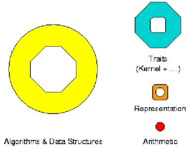
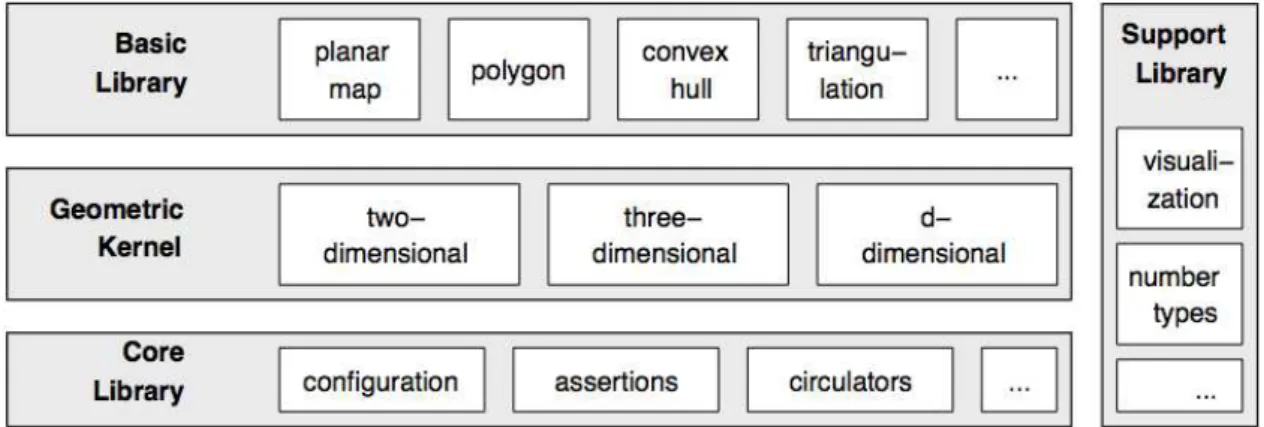
Design It is a modular library composed by several layers, and can be seen as struc-tured in three layers together with a support library for visualization purpose. The core library have the basic non-geometric functionality. The kernel library have the basic ge-ometric objects, like points and lines and basic operations to work with them such as computing intersection and distance among objects, it is also split in three parts to deal with two-dimensional, three-dimensional and general-dimensional objects, having for all dimensions Cartesian and homogeneous representations. Finally the basic library has more complex geometric objects and data structures such as polygons and algorithms to work with there data structures such as convex hull or the union of two polygons.
Packages CGAL is structured under packages according to their purpose we will make a presentation of the relevant packages to our work and how can they be used on this work. Looking at CGAL packages we find the Principal Component Analysis package that is composed of functions to analyze sets of 2-dimensional and 3-dimensional point sets, such as the computations of axis-aligned bounding boxes, centers of mass and prin-cipal component analysis. All of them will be needed on this project, also this prinprin-cipal component analysis allow us to perform the computation of moment of inertia for sur-face triangle meshes[GAP08], needing only to convert the representation of an object to a set of tetrahedra. The Surface Reconstruction from Point Sets package has a set of meth-ods that could allow to extract a mesh from a point set, extracting an isosurface2 from the dataset and reconstructing the surface as a set of tetrahedral, this brings the ability to after that make the principal component analysis and also the other characterizations needed.
As seen this library have the fundamentals to figure geometric indicators from objects that is needed in our work and it is our main choice for the development of the project.
Triangulations The classes under CGAL triangulation package have two template pa-rameters providing the geometric traits and the data structure to use on the underlying triangulation. It have two- and three-dimensional triangulations from a set of points and they are represented as a simplicial complex whose domain is not restricted to interior of the points to be triangulated but covers their convex hull. [BDTY00] One can found un-der the two-dimensional triangulations on a plane several triangulations such as a Delau-nay, regular, constrained and constrained Delaunay triangulations, in three-dimensions CGAL doesn’t provide constrained and constrained Delaunay triangulations.
Here we will focus under the 3D Delaunay triangulation package presented by CGAL and mainly they provide the partition of the spaceRdonto cells ofd+ 1vertices, some of those vertices are defined as infinite and are linked to each face of the convex hull from
2. OBJECTCHARACTERIZATION 2.2. Relevant Work
Figure 2.3: Structure of CGAL. [FGKSS98]
the point set, that way is possible to enclose the full space and allow to deal with degen-eracies3. Those infinite vertices don’t have no geometrical meaning but will simplify the computation by easily identifying the facets that belong to the surface from the object.
Triangulation Implementation Design The triangulations on CGAL are provided by a model that separates the combinatorial structure from the geometric information, it is built upon two layers. The combinatorial structure, belong to the top layer, and is provided by the triangulation data structure that is parameterized with the geometric kernel. This layer is presented as a model for example in the case of the regular and de-launay triangulations providing implementations for them. Then the vertex and cell base classes, belong to the bottom layer, they store the elementary incidence and adjacency and other geometric information and are parameterized by the triangulation data structure. This is a very modular architecture allowing to extend the basic functionality over the cells and vertexes easily extending those classes, or replacing for example the underly-ing triangulation data structure. This structure is used through the CGAL library where triangulations are needed, for example the alpha-shapes package is parameterized with a triangulation data structure and implement specific cell and vertex base classes with information for the alpha value for that cell.
Surface Extraction CGAL provides several algorithms to extract a surface from an ob-ject, most of the algorithms presented are very time demanding but thealpha-shapes pack-age provides a rapid extraction of an approximate mesh from the point set. Since it could be directly mapped to our data and that the processing times are reduced we have used thealpha-shapespackage to extract the mesh from an object. Under this package besides the common fixedalpha-shapethat is parameterized with analpha-value,CGALalso pro-vides methods for finding the minimalalpha-valuethat fully covers the surface.
3
2. OBJECTCHARACTERIZATION 2.2. Relevant Work
2.2.2 Data Persistency
In order to achieve data persistency one could use adbms. Although providing a frame-work to easily store and retrieve some data, it also provides the portability and flexibility to easily extend the system that we are targeting. Next we introduce the general design ideas from some existent dbms’s and we will look at their characteristics targeting the goals on this project.
DBMS Is a software program that enable users to create and maintain databases. Over the years it have become a very complex system where the data can be stored and re-trieved in a very efficient way. The most common form of DBMS is a relational database, also known as RDBMS, where the data is stored into tables that have relationships be-tween them, that is also what we will use.
Design CommonlyDBMS’sstores the data values in a row-store fashion way, where the tuples are stored in sequential blocks on memory or disk[Pla11]. This form of architecture fits well for query insertions, where the inserted rows could be inserted without over-head, and simple queries where some row is retrieved, but not so well for column scans where the retrieved data isn’t contiguous. This row oriented architecture was mainly ori-ented to maximize the I/O traffic on queries and thus minimizing the number of block read/writes[Bon02]. This has append mainly because hard disks are used to store the data, so DBMSs are optimized to it. But with that a problem arises, because of this data organization even if one wanted to optimize the database performance using lower la-tencies memories, such as main memory, the data isn’t optimized for those devices, so several penalties arise of using this design on different hardware with different capabil-ities. Although the increasing frequencies of memory is stalled their sizes continuos to increase and todays computers have good amounts of it for low costs, this with the re-duced latencies compared to hard disks, seems to be a good reason to justify their usage on current DBMS.
ACID Also it is typical for DBMS’s to comply with atomicity, consistency, isolation and durability properties known as ACID. These are important rules when designing a suc-cessful commercial DBMS cause they bring guarantees to the stored information and the transactions that are issued will remain consistent even under system failures. They are capable of multiple connections allowing several clients to perform simultaneous queries to the database. Unfortunately this brings more complexity and overhead in transactions and DBMS core system making it a very reliable software but with some loss in perfor-mance.
2. OBJECTCHARACTERIZATION 2.2. Relevant Work
be more easily created, and we also guarantee interoperability among different DBMS frameworks.
There are several DBMS frameworks available, and currently the target machine will run under Microsoft Windows, we will flavor one that is capable of running on that operating system. We have studied two DBMSs, the MonetDB and CSQL, both are RDBMSs fully supporting the SQL has query language, have a main-memory design and are column-oriented. CSQL although of being an open source solution the server-side only have binaries under Linux, so we have preferred the Monet.
2.2.2.1 MonetDB
Monet is a in-memory open source relational DBMS that has a complete vertical frag-mentation of data, is column oriented, optimized for query intensive applications and it was designed with focus on bulk processing[Bon02]. Monet stores each column in a bi-nary association table(BAT) table, so a column composed by a set of records is stored as a set of (key,value) tuples, being the key the identifier for the current record line on that column and the value the actual value for that record on the column. BAT’s are mapped to memory using memory mapped files as two memory arrays. A relational algebra have been implemented in order to work with this BAT files, and every results for the queries are also a collection of BATs.
Column-oriented RDBMS Monet was designed so it can be a backend RDBMS plat-form capable of interpreting several language and coupling with other DBMS systems that could rely on Monet to store the data in a column-oriented way and highly optimized for queries. It it focused on query intensive applications and the framework is designed to explore the usage of the underlying hardware and optimizing their data structures to main a memory execution, reducing at the maximum the CPU stalls, so optimizing its performance.
MAL In order to perform all the logic of a relational model, Monet have a BAT al-gebra that accomplishes that. The BATs and alal-gebra stay inside the MAL4 framework. This is a assembly-like language that the Monet core is capable of executing and have all the functionalities to perform the operations of a typical DBMS on this column-fashion architecture. This intermediate language provides the abstractions needed to allow inter-operability with other DBMSs and allow for good performance optimizations.
Architecture At it architectural design Monet is composed of three layers, on the top level are the query compilers that translate the queries from SQL, or other languages, to algebraic query plans. Bellow the query layer is an optimization layer that optimizes the generated MAL algebraic plans to a more compiler friendly MAL execution plan,
2. OBJECTCHARACTERIZATION 2.2. Relevant Work
exposing several tight loops that help compilers to achieve better instruction parallelism and thus optimizing the performance. The bottom layer is the execution layer that have the relational algebra used to process the MAL execution plans together with the BAT files containing the data.
Conclusion Although this column-oriented dmbs give us very good performance for querying the database the insertions of records are slower than in a typical row-oriented DBMS, this is because of the overhead needed to insert a row in several columns, in this program there are few insertion queries so the drawbacks are few.
2.2.2.2 UnixODBC
It is an open source specification for providing developers with a predictable API with which to access data sources. By choosing to use it one gains portability, since it works under all windows and linux platforms. This framework can be seen as a driver manager allowing the easily configuration of the underlying data sources, by allowing the user or the system administrator to provide files for mapping a connection to a data source, these file is called DSN, or Data Source Name, that is a file containing all the information to access the underlyingdbms.
2.2.2.3 TiODBC
Although the use of anodbcsuccessfully provides the needed portability it is quite com-plex to write a simple program to access a database since theAPIis from a very low level. For that a small library calledTiODBCis used that wrap theUnixODBClibrary making it much easier to work on with the dbms to insert and retrieve values.
2.2.3 Reducing Execution Time using Available Cores
The CPU has more than 30 years of development and since the 60’s their frequencies become much more faster than memory frequencies and interconnection buses that sup-plies them with data, since then the CPU starved for data and several techniques have been used to alleviate this problem. Modern desktop CPUs architecture are a mix of a RISC5and CISC6architectures.
2.2.3.1 Architecture
A RISC processor is simpler to implement in the form that instructions are atomic achiev-ing more efficiency and more processachiev-ing power. X86 processor architecture, the one used on main desktop computer processors, is CISC and those instructions are decoded into simpler RISC instructions, making this architecture a mix of RISC and CISC. They also
2. OBJECTCHARACTERIZATION 2.2. Relevant Work
make use of a pipelined instruction set, so are superscalar processors,[Wik12] allowing to perform multiple instructions.
SIMD Since the release of MMX from Intel and 3DNow from AMD several registers have been added to processors making them capable of SIMD7 instructions that can be used to graphics and other uses, but must be addressed with very low programming languages such as assembly also some compilers make use of this registers to achieve better performance, but in order to achieve it processors need to extract parallelism from the instructions.
Speculative optimizations Such as multiple execution units, out-of-order processing and brach prediction have been developed to increase the overall performance. Most of this developments tried to exploit the principles of temporal and spatial locality in code. CPUs are optimized to deal with few threads that have high data locality and a high percentage of conditional branches.[Gla09]
Cache Several levels of cache have been added to processors to reduce the gap between memory and processor frequencies, and avoid processor stalls. With the increased num-ber of cores inside the same die the level grow to three levels, usually distributed by one first level inside each core and a second level shared among a group of two cores, with the appearance of more cores a third level have been introduced that is shared by all cores inside the same die.
MIMD Since current processors are multi-core they belong to a MIMD8 computer ar-chitecture class where each core is seen as an independent computing unit with its local memory, and could access a shared memory between all cores. Each of those cores are capable of executing independent tasks that could share data between them or not.
2.2.3.2 Programming Models
The parallel programming models that exist may be divided into classes based on their assumptions they make about the underlying memory architecture[ref. wiki parallel computing]. On the hardware approached the communication occurs through a shared address space, so we will look at some of the APIs that exist to program this hardware. Here we will look at pthreads and OpenMP two widely used APIs to achieve paralleliza-tion in shared memory architectures.
PThreads are also known as POSIX Threads is a standard to work with threads. Several implementations are available on Unix POSIX-conformant systems and also Win-dows systems. Threads are independent flow of task that exists inside a process, 7Single-intruction Multiple-data
2. OBJECTCHARACTERIZATION 2.3. Solution Organization
they share the same process resources, but they are lighter than a process, and so can achieve better performance than a process fork. On the Pthreads API we can found several functions grouped within four groups:
• Thread management
• Mutexes
• Condition variables
• Synchronization
In order to use it programmers should break the computational work within dif-ferent threads and deal with data partitioning and synchronization among those threads. The threads are explicitly created and the paradigm to use when program-ming must be different from single threaded.
OpenMP is more recent than pthreads and tries to be a portable and scalable model for parallel programming. It accomplishes that with pragmas added to code sec-tions making them parallel, those pragmas are prepared by the compiler on a pre-processing stage, preparing that peace of code to run in parallel. The data decompo-sition provided byOpenMPis done automatically by the framework and in general the original (serial) code don’t need to be dramatically changed in order to run the new directives in parallel.OpenMPuses directives to control the number of created threads, synchronization and flow control of the work among threads.
2.3
Solution Organization
Our proposed solution is composed of one module, integrated onto the SCIRun environ-ment, that will do the characterizations using the CGALlibrary and store the results on an underlyingdbmsthroughodbc.
On the next section we start by describe a sequential version of the characteristics extraction.
2.3.1 Organization
As seen on section 2.2 the centroidand an AABB are used to compute other geometric characteristics such as PCA, as so, it has been decided to create a class that represents an identified object, where some common measures of an object have been added, e.g. centroid or axis-aligned bounding box. Those are values that could be computed incre-mentally at the time of the insertion of points on each object, that way some more complex characterizations algorithms could be built, e.g.PCAorOOBB.
The characterizations that are added to the system extend an abstract class named
2. OBJECTCHARACTERIZATION 2.3. Solution Organization
whith all the functionality to load the sample from theSCIRunenvironment. At the end of the characterization stage the resulting data from all the characterizations is stored on the specified database. In order to integrate all this work on theTomoGPUproject, aSCIRun
module have been produced containing aGUI to choose the required characterizations and set the connection details from the database connection where to store the results.
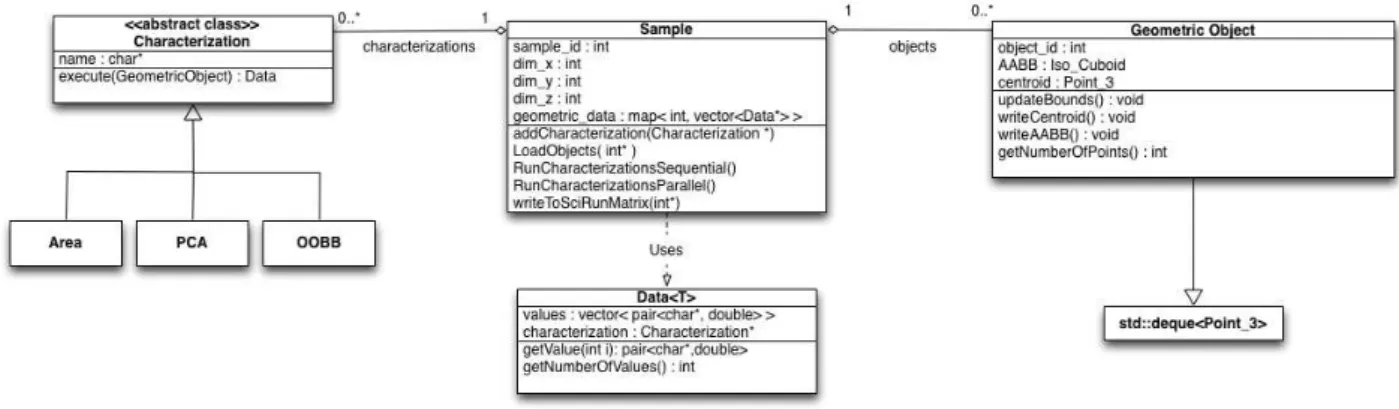
Next we look into further detail each of the early presented classes, that are also on Figure2.4.
Characterization Module It contains theGUI implemented using atcl/tkinterface onto
SCIRun, that allow to choose the required characterizations and connection details. The available characterizations arePCA,OOBBandarea, the user could also choose the name for the database connection details already configured on theodbclayer. Sample This is the class that have most of the logic for the module, it starts to load and
initialize the objects from the input into each object class storing them in a array. The number of objects on each sample and the meta information for the sample is available at the initialization of the sample, as so, it is initialized on the database that information for the sample and received an id for the sample that is stored also this class. After successfully load all object it stores each objectAABBandCentroid
values on the database and launches the computations of the characterizations on each object. At the end it fetches all the results from each object building and in-serting aSQLstring on the underlying connection for each selected characteristic. It contains the methods for creating theSQLstrings that are inserted on the database, assembling a insert string for each characterization data of that object containing on each string all of the values of that characterization.
Geometric Object Class Each loaded object is represented by a class named Geometri-cObjectthat contains some common functionality over an thee-dimensional point set. It extends the std::deque class and provides iterators over the object points. Each object besides theidfor that object have theAABBandCentroidfor that object, giving also accessors methods for that values.
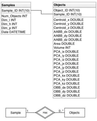
2. OBJECTCHARACTERIZATION 2.3. Solution Organization
Figure 2.5: Database Layout and Entity-Relationship diagram of the database.
Characteristic Abstraction This is an abstract class that will serve to interface all the characterization sub classes. It contains the name of the characterization, a execute function to launch the characterization on an object. The resulting data is created with the values from one characterization, as so each characteristic that extends this class must return the correct keys and values to be latter stored on the database. Data This is the data that is created by each characterization process and stored on the
sample class. It have a vector data structure with all the sub-values from that char-acterization stored in a pair<key,value>, being the key the name for the character-istic sub-value and it’s respective value represented as a double value.
2.3.2 Storage
To provide the connectivity to the database layer we have used the odbc, as explained earlier. This abstraction layer is very useful to abstract the concretedbmsused, although to be able to use it on a project usually implies to the programmer create another layer on top ofodbcto provide a simple way to interact with the database. There are already some thin libraries that could be used to do exactly that, avoiding to write such layer and more easily providing the required functionality.
2. OBJECTCHARACTERIZATION 2.4. Implementation
sample insertion the database assigns an id for the sample, that is returned in order to at the time of the insertion of the characterizations data this id for the sample could be used. Each object on a sample is already identified with an id, so we have used
2.4
Implementation
As seen previously some of the characteristics are implicit defined on the data such as the volume, others will be performed as explained on2.2.1. We next provide the implementa-tion details and discuss the results of the performed characterizaimplementa-tions, but before that we show how it is structured the internal workflow for the framework. Besides providing some characterizations the framework also have to perform the storage to the underlying database.
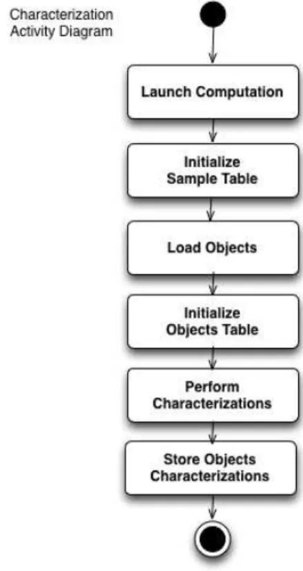
Figure 2.6: Activity diagram for the characterization module.
2. OBJECTCHARACTERIZATION 2.4. Implementation
with the data returned from the characterizations, that is stored on the sample class un-der amap<K,V>where theKis the id for the object and theVa list ofdata, is assembled a
SQLstring for each data and inserted on the database. This access to the database is per-formed at the end of the computations and is also perper-formed sequentially since we can’t guarantee that the access to the underlying database is thread safe, because that is de-pendent of the chooseddbms. Although the system is capable of correctly insert the data on the underlyingdbms, the modules are expecting that the respective tables have been previously created on thedbmsand made available through anodbcdata source file, also the name for each implemented characterization column to be stored on the characteriza-tions table is given by the key value on the data that is returned by each characterization process. The data to be inserted on the database is built as a string using the INSERT (K1,K2,K3) ON DUPLICATE KEY UPDATE VALUES (V1,V2,V3), from all the values from an object characterization data, meaning that at this finalization stage we will updaten rows on the characterization table, beingnthe number of objects on the sample.
2.4.1 PCA
PCA is done through CGAL, here the process described on2.4.1, will first extract the3×3 covariance matrix from the object points, and latter the eingenvalues and eigenvectors are extracted through linear least squares fitting over a plane. This will give the first two directions and the third one is extracted by computing the normal vector of such plane. The resulting orthogonal axis from the principal directions is centered on the computed centroid of the object.
Lets see how it can be computed under an 3-dimensional space:
Center the Data There is the need to subtract the centroid from each data, thus centering the dataset around the origin
Compute the Covariance Matrix Compute the3×3covariance matrix for the data set such as stated onA.2
Extract Features Vector This is the vector with all the three principal components, eigen-vectors and eigenvalues are extracted using linear least squares fitting
Here the data is fitted onto a plane to extract the first three principal components using least squares fitting.
2.4.2 Bounding Boxes
2. OBJECTCHARACTERIZATION 2.4. Implementation
AABB This is a trivial computation, it should be evaluated the minimal and maximal values under all axis, and extracted the values from the AABB.
OBB To extract theOBBthe initial data set is centered around origin, the are applied affine transformations to rotate the dataset to fit the principal component vectors ex-tracted previously byPCA, to each one of the planesxy, xz andyz, on each fitting one bounding box is extracted, and is retrieved the one with less area. The resulting OBB
is the represented by the three dimension values of the length, width and height of the bounding box and the three orthogonal vectors representing the principal components and the object centroid.
2.4.3 Surface Area
In order to compute the surface area it is first needed to perform an approximation of the shape from the object or to extract it’s surface mesh. With that it is possible to compute the surface area as the sum of all the areas from the exposed complexes that compose the obtained mesh or shape. We have several choices to perform this step. At a initial phase we have used the alpha-shapes package from theCGALto extract the mesh of the object. This algorithm as presented could introduce holes on the resulting mesh and with that errors on the final measurement. To avoid that and as explained the algorithm must be used with several alpha-values and for each test if the mesh is closed or not. TheCGAL
already contained all the software to provide that but on bigger samples the computing times could break the required interactivity.
A second alternative was then implemented and since the dataset received is closed and don’t have holes a simple algorithm could be implemented to extract the voxels of the surface on the initial object. As so, to compute the area first it is extracted the axis aligned bounding box from the object, and then a grid is constructed with all the voxels from the object. This is a boolean grid that has a true value if the voxel at (x,y,z) belongs to the voxels from the object and not only the surface. After that it is searched for each voxel if it belongs to the surface or not, figuring for each of the voxel six faces if there exist another voxel connected to that face, the faces that don’t have any voxel connected to it are the faces from the surface and the voxel of that face can be marked as an surface voxel.
2. OBJECTCHARACTERIZATION 2.5. SCIRun Integration
2.4.3.1 Surface Extraction
2.4.4 Tests
The framework have been tested for each one of the required computations, and the results are presented here. All the tests that are presented on this section where pro-duced on a desktop computer with a quad-core Intel Xeon E5506 @2.13 GHz cpu, 12 GB RAM DDR-3 800 MHz memory, the operation system(OS) used is Linux Ubuntu 10.04.4 LTS (kernel 2.6.32-45). All the computations perform sequentially and we obtained the following measures. The tested samples are derived from a 400x400x400 voxel 3d ma-trix, that when received has 272 objects and a total number of voxels from all objects of 2691749.
Submodule Time (s) % of the total time Initialization 0.410 65.71
PCA 0.071 11.38
OBB 0.071 11.38
Area 0.072 11.54
Finalization 0.214 34.29
Total Time 0.624 100
Initialization include the time to read all the data from the input and the initialization of all theGeometric Objectswith those data, including the initial computing of the object centroid and axis-aligned bounding box. After that each module is started and the ob-tained times are extracted since the module starts to work until it returns the data. As one could see all the characterizations are fast to execute, and the system achieves the needed interactivity.
2.5
SCIRun Integration
In this section we start by giving a brief description of how the code developed can be integrated in theTomoGPUsystem as aSCIRunmodule. In a second part we show how the characterization module is positioned in the global system.
2. OBJECTCHARACTERIZATION 2.6. Parallelization
2.5.1 How to turn the standalone code in a SCIRun module
SCIRun is organized as pipeline of modules, where the execution of a module is fired by the arrival of data at an input port. The data sent by the previous module corresponds to a SCIRun mesh object, where the 3D matrix data is accessible.
On appendixBone could see how the interaction withSCIRunis achieved.
2.5.2 Module position in the TomoGPU software
The characterization module receives a sequence of integers with the following organi-zation
• an integer with the number of objects
• for each object
– the ID object identification
– the number N of voxels of the object
– N integers, one for each voxel; each integer C represents the voxel position in the sample. Being L, H and P the dimensions of the sample, respectively in x, y and z, This integer is coded as
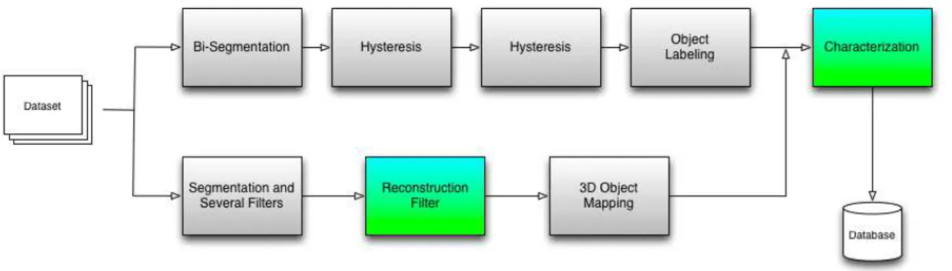
C=L×H×z+L×y+x
This format is produced by the Object Labeling module represented in figure2.7; the output of this module can be processed by the object cleaning module. This module can eliminate objects according to a given criteria - for example, deleting objects that are too small.
This module does not have an output port, as it is the last step in the pipeline. Its output is the already mentioned database of objects with its relevant characteristics.
2.6
Parallelization
2.6.1 Approach
There are several ways to provide parallelization and the system architecture provided the independence among different characterizations, as so, we have choosed to paral-lelize all the objects and their characterizations, that way when a new characterization is added to the system it will be launched in parallel with all the others. Instead of parallelizing the computations among several objects it could be also parallelized each characterization algorithm. Since the algorithms are relatively simple and with linear complexity, they don’t justify their parallelization, in either cases any characterization further added to the framework could also be parallelized.
2. OBJECTCHARACTERIZATION 2.6. Parallelization
Figure 2.7: General organization of the TomoGPU system.
1 initialization phase 2 for all objects on sample
3 for all characterizations
4 characterization->execute(object) 5 finalization phase
To provide the parallelization we usedOpenMP, and there are two phases that run in sequential, as so, couldn’t be parallelized. A first initialization phase where all the data is loaded and the objects initialized, and a finalization phase where the data is stored on the database.
2.6.1.1 Characterizations Parallelization
Each individual characterization is independent from all the other characterizations and it was possible to launch every characterizations on each object in parallel. The sample file was changed in order to launch all the characterizations on parallel, adding a omp parallel forpragma on the first for loop, executing the loop over the determined number of threads. On this work only the three characterizationsOOBB,AreaandPCAare launched in parallel, but that number may increase with the introducing of new characterizations. Next we show the results for this parallel implementation comparing them with the first sequential implementation.
2. OBJECTCHARACTERIZATION 2.6. Parallelization
2 for all objects on sample
3 #pragma omp parallel for 4 for all characterizations
5 characterization->execute(object) 6 finalization phase
Sample 2 Threads 4 Threads 8 Threads
100×100×100 − − −
200×200×200 − − −
400×400×400 0.553 0.563 0.575
2.6.1.2 Objects Parallelization
The different objects on each sample are also independent and after successfully loaded all the objects, all the objects could be analyzed in parallel through the usage of an OpenMP pragma parallel for.
1 initialization phase 2 #pragma omp parallel for 3 for all objects on sample
4 for all characterizations
5 characterization->execute(object) 6 finalization phase
Sample 2 Threads 4 Threads 8 Threads
100×100×100 − − −
200×200×200 − − −
400×400×400 0.534 0.526 0.565
2.6.1.3 Collapsing Work
2. OBJECTCHARACTERIZATION 2.7. Conclusion
Sample 2 Threads 4 Threads 8 Threads
100×100×100 − − −
200×200×200 − − −
400×400×400 0.549 0.507 0.540
2.6.2 Conclusion
The parallelization techniques employed on the characteristics extraction allow to fully use the processing power of theCPUallowing more characterizations to be launched in parallel and providing an interactive workbench.
2.7
Conclusion
The number of cores that can be added to SMParchitectures is limited, typically SMP
3
Object Reconstruction
In this chapter we deal with the reconstruction of the surface from a point set sampled on an object surface. We start to introduce the problem that must be solved and take a survey over some mathematical concepts required to perform such reconstruction. After this introductory stage we dive onto the most common used techniques to perform such reconstruction introducing the available algorithms and what are the available libraries to perform it. At the end of this chapter we show how the implement features are organized and discuss about what are the improvements that can be applied and how some of them are achieved in order to reduce the overall reconstruction time.
3.1
Problem
The presented problem can be generically seen as the extraction of a triangular mesh of an object surface from a unoriented and unorganized point set that contains a several amount of noise.
3.1.1 Problem Definition
![Figure 1.2: Overall view of Tomo-GPU modules [Ea12]](https://thumb-eu.123doks.com/thumbv2/123dok_br/16529958.736266/17.892.151.825.136.504/figure-overall-view-of-tomo-gpu-modules-ea.webp)
![Figure 1.3: Overall view of SCIRun computational workbench [Ins13]](https://thumb-eu.123doks.com/thumbv2/123dok_br/16529958.736266/18.892.119.733.643.1077/figure-overall-view-scirun-computational-workbench-ins.webp)