Effect of Boride Layer on PM HSS AISI M2 on the Mechanisms Acting in the Transverse
Rupture Strength Test
Mateus Leal Arcegoa*, Júlio César Giubilei Milana, César Edil da Costaa,
Elisangela Aparecida dos Santos de Almeidaa
Revised: January 27, 2017; Revised: June 06, 2017; Accepted: October 05, 2017
Herein, it was conducted a study in order to examine the main fracture characteristics in the transverse rupture strength test (TRS) of a high speed steel (HSS) AISI M2 produced by powder metallurgy (PM) and with boriding treatment. Four conditions have been studied: as-sintered, borided, normalized and borided + TiN. The TRS tests were conducted in accordance with ASTM B528-12 standard. Density, Vickers hardness and transverse rupture strength properties were evaluated. Fractography was observed by scanning electron microscope (SEM). TRS test in the as-sintered condition had the best performance. The fractography of samples showed very irregular appearance, with interconnected porosity for the matrix of the samples and the boride layer had a smooth surface with low porosity. It
was observed on the boride layer, the growth of boride layers inside the pores, filling them, which is a
positive factor on the TRS. However, cracks were observed in the FeB/Fe2B interface of boride layer, which embrittle the material and reduce the TRS. In fractography of borided samples, it is observed
that two fracture modes occur, mode I and mode II. This should be explained owing to the difference
between the elasticity modulus of FeB and Fe2B interface.
Keywords: boriding, fracture modes, fractography, Transverse rupture strength
*e-mail: [email protected]
1. Introduction
The wear resistance, high mechanical strength and the possibility of near net shape manufacturing led to the increasing relevance of powder metallurgy steels in the tool manufacturing or automotive sector1,2. The cost reduction as compared to a conventional production process, is the most promising advantage of the powder metallurgy3,4. PM
properties are affected by several parameters such as the
shape, size and the composition of the powder particles, lubricant type, compacting pressure, sintering temperature
and time, and finishing operations5. The microstructure of as-cast high speed steels, consists of a matrix and eutectic carbides heterogeneously distributed in the interdendritic regions6,7.
The surface treatments allows to meet a wider range of parts requirements, such as increased hardness in combination with good toughness8. The boriding is a thermochemical treatment technique used in many areas of engineering
processes of metals, where the boron atoms are diffused
in the surface to form borides with the base metal8-10. The boron atoms owing to its relatively small size and high
mobility can diffuse into the substrate. Diffuse easily into
ferrous alloys, forming FeB (16.23 %p B) and Fe2B (8.83 %p B) intermetallic, non-oxide, ceramic borides11,12. The outermost layer is FeB, while Fe2B is the innermost. Below the composite layer (FeB and Fe2B) the diffusion zone hardly
exists due to the fact that boron have very low solubility in
iron. The growth of borides layer is dominated by diffusion
of boron through the phase Fe2B13,14.
The flexural strength and fracture toughness are completely different concepts in the context of solid mechanics. Transverse
rupture strength is a static tensile property while the fracture toughness is a measure of the resistance of a material to crack propagation15. The results for fracture toughness make no distinction to the high speed steels which are obtained by
different processing techniques, so it became common to
evaluate the toughness of these materials using static testing of three point bending, because of its ability to detect small changes in the material16. The TRS defines the probability of nucleation of a crack in stress concentrators inherent to the material and processing17. For the occurrence of crack propagation, it is necessary that the stress at its tip be greater than the theoretical cohesive strength of the material. However, with current technologies it is not possible to measure the stress at the tip accurately18. This test method is used to measure the strength of sintered, including post-treated specimens19.
TiN coatings, has good adhesion and coating on high speed steels20. The addition of a TiN coating on the boride layer is seen as a possibility of reduction in the rate of crack propagation, since there is a change in behavior in the stress-strain curve between the coating and the sample.
The aim of this work is to analyze the influence of boride
layer on high speed steel AISI M2 and mechanisms of the aGrupo de Metalurgia de Pó e Superfície, Centro de Ciências Tecnológicas, Universidade Estadual de
transverse rupture strength. The TRS test is performed in order to rupture the samples, after the tests the samples were analyzed using a scanning electron microscope. The main mechanisms acting to the rupture of the material were highlighted.
2. Material and Methods
The material involved in the research, is the AISI M2 high speed steel produced by powder metallurgy. The chemical composition of the material is shown in Table 1.
M2 steel powder atomized in water was used to produce the samples. The samples were prepared by cold uniaxial pressing. Zinc Stearate was used as the matrix lubricant and the compaction pressure was 700 MPa. The sintering process occurred in a tube furnace under vacuum atmosphere at a temperature of 1270°C for one hour. The heating rate was 5 °C/min.
The specimens sizes are in accordance to MPIF STANDARD 4121, establishing that its length is 31.7 mm, 12.7 mm width and 6.35 ± 0.13 mm thick.
The boriding treatment was carried out in a muffle
furnace. The boriding powder was the commercial mixture Ekabor®. The specimens were placed into the stainless steel
container that was filled with approximately 15 mm of the
mixture, respecting the same distance between the samples and the container walls. The container was closed with a stainless steel cover. Silica sand was placed on the cover to prevent gas escape during boriding. Boriding cycle follows parameters found in Krelling's work22; the samples are heated to a temperature of 1000 °C and maintained at this temperature for 2 hours. Cooling was performed in air to room temperature to avoid excessive grain growth.
The treatment of normalizing was performed with the same parameters of the boriding treatment, to evaluate the
behavior of the material matrix without the effect of boriding
agent - Ekabor®. Thus, it will be possible to evaluate the
influence of boride layer on the material properties. Therefore,
it used the same container used in boriding with granular protection to avoid decarburization of the material.
Previously to film deposition, shot peening was applied
to the surface using glass microspheres with the purpose of removing surface contamination and obtain a homogeneous
roughness. TiN film was deposited on borided samples by
a PVD process.
The geometric densities were calculated for the green, sintered and thermochemically treated materials by means of mass ratios and volume. For the determination of the masses it was used a digital analytical balance. To calculate the relative density obtained by the ratio (measured density/
Table 1. Chemical composition of AISI M2 HSS used in this work (weight %)
C Cr Co Mn Mo Si V W
0.80 4.13 1.00 0.30 5.00 0.45 1.90 6.50
theoretical density) x 100 % it is required the theoretical density of the material based on chemical composition, observed in Table 2.
The test for transverse rupture strength was carried out following the instructions of the standards ASTM B528-12 and MPIF STANDARD 4119,21. The load application speed used was 2.5 mm/minute. The application of the load was taken until the sample failure. Transverse rupture strength was calculated according to the equation (1) found in19:
(1)
Where P is the applied load until failure the sample (N), L is the distance between the support rods (mm), t is the sample width (mm) and w is the sample thickness (mm). A scanning electron microscope (SEM) was used for the samples characterization in order to analyze porosity levels, arrangement of carbides and fractured region. Nickel coating was deposited by an electrolytic process with the aim to retain the edge in order to get a better view of the material surfaces during the microstructure analysis. Subsequently, the samples were polished with alumina and etched with Nital 3%.
Vickers microhardness measurements with 25g load were carried out in the cross section of the samples. The 25g load was selected in order to consistently measure the layers of borides. With indentation times of 10 seconds each, 8 measurements were performed on each samples condition.
3. Results and Discussion
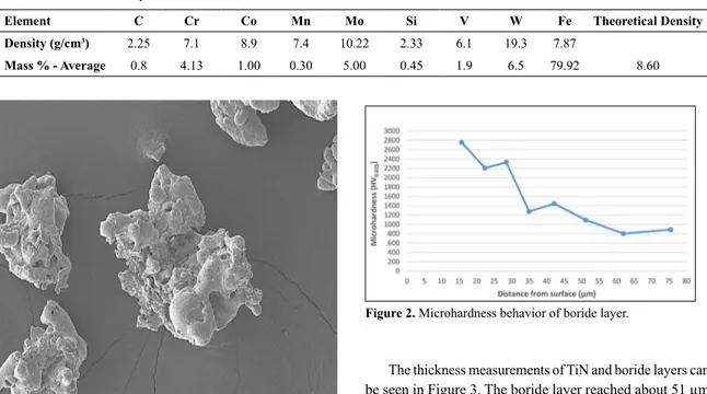
Figure 1 shows the morphology of the AISI M2 high speed steel powder. The irregular shape of the powder is characteristic of the water atomization process.
Green density ranged from 6.34 g/cm³ and 6.47 g/cm³, with an average density of 6.38 g/cm³. Since the density of sintered material ranged from 7.16 g/cm³ and 7.46 g/cm³, with an average density of 7.32 g/cm³.
With the geometric density values obtained, the relative density of the material was calculated, which represents the
achieved densification level, i.e. the level that the material
density reached compared to the theoretical density. A relative density of 100% means that the material has no porosity. The values of relative density are shown in Table 3. It can be seen from these values that the level of porosity varies around 15%. According to the authors23, porosity values for powder metallurgy generally are in the range of 5 to 15% of the volume of the piece. Therefore, these values are acceptable to obtain consistent results on the transverse rupture strength.
. .
/ . .
TRS
3
P L
2
t w
2Table 2. Theoretical density of AISI M2 HSS
Element C Cr Co Mn Mo Si V W Fe Theoretical Density
Density (g/cm3) 2.25 7.1 8.9 7.4 10.22 2.33 6.1 19.3 7.87
Mass % - Average 0.8 4.13 1.00 0.30 5.00 0.45 1.9 6.5 79.92 8.60
Figure 1. Powder morphology of AISI M2 HSS - SE mode.
Table 3. Geometric and relative density of each condition
Condition Average Density
[g/cm3]
Average Relative
density [%] Porosity [%]
Max. Density [g/cm3]
Max. relative density [%]
As-Sintered 7.34 ± 0.07 85.35 ± 0.80 14.65 ± 0.80 7.41 86.12
Normalized 7.30 ± 0.12 84.87 ± 1.40 15.13 ± 1.40 7.46 86.70
Borided 7.31 ± 0.08 85.03 ± 0.89 14.97 ± 0.89 7.44 86.47
Bor + TiN 7.30 ± 0.26 84.88 ± 2.98 15.12 ± 2.98 7.52 87.44
Table 4. Vickers microhardness of each condition in study
Sample Relative Density (%) Average (HV0.025)
As-Sintered 86.05 633.86 ± 87.73
Normalized 84.53 1097.61 ± 173.29
Borided Layer 86.47 2094.90 ± 171.26
Matrix of Borided Sample 86.47 1024.40 ± 79.66
The Vickers microhardness of samples are shown in Table 4.
Chang, Jao, et al.24 show hardness values (HV 0.025) of a conventional high speed steel M2 with and without coating of TiN. Samples of M2 steel without TiN coating reach values of 630 HV, whereas the M2 steel samples having TiN coating reach values about 1893 HV. The TiN hardness are 2500 HV according to Bodycote-Brasimet.
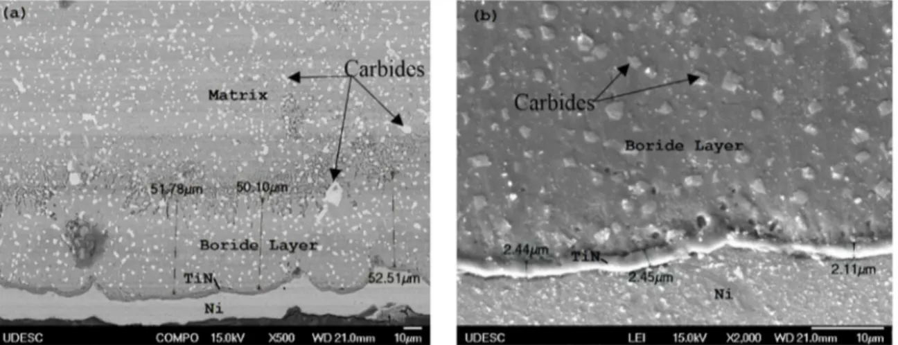
Figure 2 shows the decrease in microhardness for the borided sample from the layer to the sample substrate. There was a decrease of about 1000 HV0.025 near the transition layer/substrate. By reaching the substrate, microhardness stabilize at about 800 HV0.025.
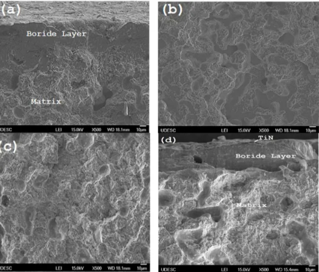
The thickness measurements of TiN and boride layers can be seen in Figure 3. The boride layer reached about 51 µm and the TiN layer of about 2.3 µm. Typical carbides from AISI M2 are shown by arrows. The deterioration of adhesion can be explained by the high level of internal stresses generated
in these films and the mismatch of the substrate mechanical
properties with considerably high hardness25. Adhesion can be improved by a mechanical surface process called shot peening, which inserts compressive stresses on the surface
prior to deposition of the film, reducing the high internal stresses typically found in film deposition.
Figure 4 graphically shows the transverse rupture strength results for each condition. It is observed that the as-sintered condition had the best results comparing to the others. An
analysis of variance with 95% confidence level showed that the difference on the results are statistically significant. Thus,
it can be said that the boride layer reduces the transverse rupture strength around 13% compared with the sample without layer (normalized) and around 25% compared to the
Figure 3. Cross section of (a) boride layer - BSE mode and (b) TiN layer - SE mode.
Figure 4. Results of transverse rupture strengths.
as-sintered sample. The TRS shows a very high sensibility to the porosity levels as previously discussed by Olsson and Fischermeister26 the crack nucleation is facilitated by the presence of the defects originated by the fabrication process, like porosities. Yilmaz and Varol5 investigated
the effect of boronizing process on Höganas ASC 100.29
iron based powder. The boronizing treatment promoted the formation of a Fe2B single layer. The authors conducted three point bending tests and found that TRS has increased by approximately 8% in the borided samples over the only sintered samples. The authors conducted shot peening with
different intensities and concluded that high intensities of
shot peening should be avoided because it deteriorates the borided surface. The boriding increased the hardness of only-sintered material from 200 HV to 1800-2500 HV.
Historically, it has been quoted by application engineers in the industry that TRS is inversely proportional to hardness. TRS increases when hardness decreases27,28. It can be seen from the results that despite the same hardness of the matrix, the sample with boride layer shows a lower performance on TRS compared to sample without borides
layer (normalized). This shows that the boride layer affects
the speed of propagation of cracks, causing the material to break more quickly, hence obtaining smaller TRS values.
The transverse rupture strength tests resulted in the rupture of the samples, acquiring irregular fractography and a very high percentage of cracks.
Figure 5 shows fractured region of the samples under study. In Figure 5 (a) and Figure 5 (d) it is remarkable the change in the form of fracture between the boride layer and the sample matrix. The matrix of all conditions has a certain ductility and interconnected porosity which facilitates the propagation of cracks. It is also observed in Figure 5 (a) and Figure 5 (d) that the boride layer has a smooth surface with almost no porosity. Isolated porosity results in more homogeneous deformation, while interconnected porosity causes an increase in the localization of strain at relatively smaller sintered regions between particles. Thus, interconnected porosity is more detrimental and reduces macroscopic ductility to a greater extent than isolated porosity29.
Figure 6 shows several cracks propagation, indicated by arrows, that starts in a single pore. This factor is predominant in transverse rupture strength and explains why the highest amount of pores in the material, results in a lower transverse
rupture strength. Griffith's theory explains that a crack will
propagate when the decrease in elastic strain energy is at least equal to the energy required to create the new crack surface18. At the meet of cracks during its propagation, the
crack finds no resistance, extra energy is not necessary to
create another crack, and so their speed of propagation increases, causing the rupture of material more quickly.
The boride layer showed a smooth fracture with almost no porosity, this fact can be explained by the growth of borides
layer on the pores, filling them and reducing the effect of cracks in this region, as observed in Figure 7. This filling
Figure 5. Fractography of (a) boriding, (b) as-sintered, (c) normalized and (d) Bor + TiN samples (SE mode).
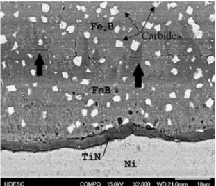
Figure 8. Boride layer FeB/Fe2B interface showing the crack propagation - BSE mode.
Figure 9. Fracture modes on boride layers (a) 1000x - SE mode, (b) 2000x - SE mode and (c) 2000x - BSE mode.
hardness increase, the results found here corroborate with the results found in literature. Comparing the hardness of the samples, there is an increase of more than 70% in the hardness of the normalized samples comparing to the as-sintered samples (TRS of normalized samples decreased 16%) and an increase of about 230% in the hardness of the borided samples comparing to the as-sintered samples (TRS of borided samples decreased 25%).
The borided layer here produced consists in a biphasic layer of FeB and Fe2B due to the presence of high content of alloying elements in AISI M2 steel. As reported in literature there is a residual tensile stresses at the vicinity of the interface between FeB and Fe2B, which upon loading can result in fracture and spalling of the layer. Figure 8 shows the
fracture indicated by arrows. This factor is due to different thermal expansion coefficients of the phases (α (FeB) = 23
x 10-6/°C, α (Fe
2B) = 7.85 x 10
-6/°C)30 and because of the
differences in their inherent stress level (Fe2B = compressive
stress, FeB = tensile stress)11. The presence of this biphasic layer reduced the TRS of the borided samples due to the formation of cracks in the interface of the layers. As Fe2B
phase has a lower coefficient of thermal expansion and is less
brittleness than FeB, this layer is most desirable in industrial applications31. A single Fe
2B phase can be obtained from a double FeB-Fe2B phase by a subsequent vacuum or salt bath treatment for several hours above 800 °C, which may be followed by oil quenching to increase substrate properties32.
Figure 9 shows the fractography of the boride layer. The literature treats three types of cracks, termed mode I, II, and III. The mode I is called the normal opening mode, where the tensile stress is normal to the faces of the crack. The mode II and mode III are sliding mode of shear, where the stress is normal to the advancing edge and parallel to the advancing edge, respectively33. It can see that there are two fracture modes, which are highlighted in Figure 9 (c), mode I and mode II. This fact can be explained by discontinuity in Young's modulus between FeB and Fe2B phases (590 GPa and 285 GPa, respectively31), which drastically changes the behavior of the stress-strain curve, generating a large
concentration of tension in the region. The difference between
the FeB and TiN elasticity modulus is smaller if compared to FeB/Fe2B interface, 600 GPa for TiN34 and 590 GPa for FeB, and also for Fe2B and the substrate of M2, are 210 GPa for M231 and 285 GPa for Fe
2B.
4. Conclusion
This study was conducted in order to examine the main fracture characteristics in the transverse rupture strength test (TRS) of a high speed steel (HSS) AISI M2 produced by powder metallurgy (PM) and with treatment of boriding. The following conclusions were obtained.
- The Vickers hardness for the boride layers reached an average of approximately 2100 HV0.025.
- Boriding treatment is benefic to sealing porosities
due to the growth of the borides crystals inside the porosities.
- The TRS shows a very high sensibility to the porosity levels because the presence of pores facilitates the crack nucleation.
- TRS decreases when hardness increase. - The borided samples had a low performance on TRS results against the samples without layers. The addition of a biphasic boride layer reduces TRS at
approximately 13%, due to the differences on the
properties found in these two phases that can cause crack formation in the interface.
differences in the coefficient of thermal expansion
of the phases.
- In fractography of borided samples it can be seen that occur two opening modes of cracks, the mode I, Normal opening mode, and the mode II, shear sliding mode. This fact might be explained by the discontinuity in the Young's modulus of the phases, generating a high concentration of tension in the region.
Thus, control over the boriding parameters to obtain only the phase Fe2B boride layer may lead to best results with regard to transverse rupture strength.
5. Acknowledgements
The authors wish to thank the company Bodycote-Brasimet for the PVD process of TiN on samples and Docol Faucets for the nickel to nickel plating the samples. The Authors also wish to thank G. de Faveri and G. Espindola (UDESC, Brazil) for experimental assistance. Thanks to CAPES for
the full scholarship. Thanks to FAPESC for financial support
to the PhD student in the surveys.
5. References
1. M'Saoubi R, Czotscher T, Andersson O, Meyer D. Machinability of Powder Metallurgy Steels Using PcBN Inserts. Procedia CIRP. 2014;14:83-88.
2. Lane M, Smith P. Developments in Sintered Valve Seat Inserts.
SAE Transactions. 1982;91(1):916-924.
3. Liu ZY, Loh NH, Khor KA, Tor SB. Sintering of injection molded M2 high-speed steel. Materials Letters. 2000;45(1):32-38.
4. Bolton JD, Gant AJ. Microstructural Development and Sintering Kinetics in Ceramic Reinforced High Speed Steel Metal Matrix Composites. Powder Metallurgy. 1997;40(2):143-151.
5. Yilmaz SS, Varol R. The effect of surface hardening treatments on the mechanical properties of iron based P/M specimens.
Powder Technology. 2010;204(2-3):236-240.
6. Zhou XF, Fang F, Li F, Jiang JQ. Morphology and microstructure of M2C carbide formed at different cooling rates in AISI M2 high speed steel. Journal of Materials Science. 2011;46(5):1196-1202.
7. Bocallini MJ Jr., Corrêa AVO, Goldenstein H. Rare earth metal induced modification of γ-M2 C, γ-M6 C and γ-MC eutectics in
as cast M2 high speed steel. Materials Science and Technology. 1999;15(6):621-626.
8. Oliveira CKN, Benassi CL, Casteletti LC. Evaluation of hard coatings obtained on AISI D2 steel by thermo-reactive deposition treatment. Surface and Coatings Technology. 2006;201(3-4):1880-1885.
9. Campos I, Oseguera J, Figueroa U, Garci´a JA, Bautista O, Kelemenis G. Kinetic study of boron diffusion in the paste-boriding process. Materials Science and Engineering: A. 2003;352(1-2):261-265.
10. Chen XJ, Yu LG, Khor KA, Sundararajan G. The effect of boron-pack refreshment on the boriding of mild steel by the spark plasma sintering (SPS) process. Surface and Coatings
Technology. 2008;202(13):2830-2836.
11. Bindal C, Üçisik AH. Characterization of borides formed on impurity-controlled chromium-based low alloy steels. Surface
and Coatings Technology. 1999;122(2-3):208-213.
12. Allaoui O, Bouaouadja N, Saindernan G. Characterization of boronized layers on a XC38 steel. Surface and Coatings
Technology. 2006;201(6):3475-3482.
13. Béjar MA, Moreno E. Abrasive wear resistance of boronized carbon and low-alloy steels. Journals of Materials Processing
Technology. 2006;173(3):352-358.
14. Ozbek I, Bindal C. Kinetics of borided AISI M2 high speed steel. Vacuum. 2011;86(4):391-397.
15. Fang ZZ. Correlation of transverse rupture strength of WC-Co with hardness. International Journal of Refractory Metals &
Hard Materials. 2005;23(2):119-127.
16. Beiss P, Wahling R, Duda D. Toughness of Vacuum Sintered P/M High Speed Steels. Modern Developments in Powder
Metallurgy. 1985;15-17:331-357.
17. Fischmeister HF, Olsson LR. Fracture Toughness and Rupture Strength of high speed steels. In: International Conference of
Cutting Tool Materials; 1980 Sep 15-17; Mitchell, KY, USA.
p. 15-17.
18. Dieter GE, Jr. Mechanical Metallurgy. 1st ed. New York:
McGraw-Hill; 1961.
19. ASTM International. ASTM B528-12 - Standard Test Method for Transverse Rupture Strength of Powder Metallurgy (PM)
Specimens. West Conshohocken: ASTM International; 2012.
20. Velasco F, Gordo E, Isabel R, Ruiz-Navas EM, Bautista A, Torralba JM. Mechanical and wear behaviour of high-speed steels reinforced with TiCN particles. International Journal of
Refractory Metals and Hard Materials. 2001;19(4-6):319-323.
21. MPIF Standard Test Methods. MPIF Standard 41. Princeton: Metal Powder Industries Federation; 1991.
22. Krelling AP, Milan JCG, Costa CE. Tribological behaviour of borided H13 steel with different boriding agents. Surface
Engineering. 2015;31(8):581-587.
23. Wu MW, Shu GJ, Chang SY, Lin BH. A Novel Ni-Containing Powder Metallurgy Steel with Ultrahigh Impact, Fatigue, and Tensile Properties. Metallurgical and Materials Transactions A. 2014;45(9):3866-3875.
24. Chang CL, Jao JY, Ho WY, Wang DY. Effects of titanium-implanted pre-treatments on the residual stress of TiN coatings on high-speed steel substrates. Surface and Coatings Technology. 2007;201(15):6702-6706.
25. Tavsanoglu T, Jeandin M, Addemir O, Yucel O. A functionally graded multilayer approach to the synthesis of boron containing ceramic thin films. Solid State Sciences. 2012;14(11-12):1717-1721.
26. Olsson LR, Fischmeister HF. Fracture Toughness of Powder Metallurgy and Conventionally Produced High-Speed-Steels.
27. Almond EA. Deformation Characteristics and Mechanical Properties of Hardmetals. In: Viswanadham RK, Rowcliffe DJ, Gurland J, eds. Science of Hard Materials. Boston: Springer; 1983.
28. Bonjour C. Nouveaux développements dans les outils de coupe en cárbure fritte. Wear. 1980;62(1):83-122.
29. Chawla N, Deng X. Microstructure and mechanical behavior of porous sintered steels. Materials Science and Engineering: A. 2004;390(1-2):98-112.
30. Jain V, Sundararajan G. Influence of the pack thickness of the boronizing mixture on the boriding of steel. Surface and
Coatings Technology. 2002;149(1):21-26.
31. ASM International. ASM Handbook - Volume 4 Heat Treating. Materials Park: ASM International; 1991.
32. Dearnley PA, Farrell T, Bell T. Developments in plasma boronizing. Journal of Materials for Energy Systems. 1986;8(2):128-131.
33. Roylance D. Introduction to Fracture Mechanics. Cambridge: Massachusetts Institute of Technology; 2001. 17 p.