R. Viana
[email protected]A. R. Machado
Senior Member, ABCM [email protected] Federal University of Uberlândia – UFU School of Mechanical Engineering Machining Research Laboratory 38408-902 Uberlândia, MG, BrazilInfluence of Adhesion between
Coating and Substrate on the
Performance of Coated HSS Twist
Drills
This work analyses the performance of the TiN/TiCN, TiAlN, TiN/TiAlN and TiN/TiAlN/WCC coatings on HSS M2 drills used in the drilling of the aluminium-silicon alloy ISO 3522 AlSi8Cu3Fe, correlating the life of the tools to the coating adhesion characterization experiments. Coating adhesion was characterized using Rockwell C indentation tests and scratch tests with progressive load. The performance of the coatings in the life experiments was the following, in decreasing order: TiN/TiCN, TiAlN, TiN/TiAlN/WCC and TiN/TiAlN. In the adhesion characterization experiments with TiN/TiCN there were no cracks or delamination of the coatings, which justifies its best performance in the life experiments.
Keywords: coatings, high speed steel, drilling, Al-Si alloys, adhesion
Introduction
1
Hard coatings such as TiN, TiCN and TiAlN are widely employed in the metal-mechanics industry to improve the properties of machine parts, die and injection moulds, and cutting tools.
In machining, the performance of the cutting tool is measured, above all, to its tool life, which depends on the resistance to wear. The coating is normally used to ensure greater resistance. However, the use of coatings in tools implies that one more important parameter has to be analysed, which is the failure of the coating associated to the lack of adhesion to the substrate. It can occasionally lead the tool to premature wear, reducing its efficiency.
An appropriate adhesion of the coating is very important, since these films are required to endure different types of loads when they are in service, including cyclical, mechanical and thermal loads. A tool with inadequate coating adhesion can perform worse than another without coating. The formation of hard and abrasive particles, resulting from the premature destruction of the coating, accelerates the wear of the contact surfaces (Lima et al., 2005).
In general, several methods have been used to improve the adhesion in the substrate-coating interface, such as pre-treatment of the substrate, adoption of intermediate layers of coatings, multi-layer coatings or functional multi-layers. These technologies have been used to approximate or to reduce the incompatibilities between the properties of the coating and those of the substrate, trying to avoid the failure of the tool due to lack of adhesion (Bunshah, 2001).
Usually, to better understand the adhesion characteristics of thin films, it is necessary to make a distinction between "basic adhesion" and "practical adhesion" of the coatings. The "basic adhesion" is understood as the sum of all of the interatomic interactions at the substrate-coating interface. This can be quantified as the necessary work to completely separate the film from the substrate along the interface, excluding all the effects of bond nature among the atoms of both materials. The "practical adhesion" depends on the "basic adhesion", since the former is correlated to the failure of the hard coatings. The "practical adhesion" depends on a complex combination of properties of the film and substrate, such as elastic properties, fracture toughness, flaw size distribution in the microstructure of the film, pores and other defects in the latticeof the material, load conditions and behaviour to friction (Ollendorf and Schneider, 1999).
The surface engineering is interested in the assessment of the "practical adhesion" of the coatings, and many methods are used to characterize it: scratch, cavitation, impact, and Rockwell indentation tests. However, sometimes these experiments produce contradictory results of difficult interpretation, since it is usually difficult to find acceptable definitions for the substrate-coating adhesion that take into account the complexity of the effects of the material microstructure, the external load and the environmental aspects (Bunshah, 2001).
The purpose of this work was to study and to contribute to a wider discussion on the performance of TiN/TiCN, TiAlN, TiN/TiAlN and TiN/TiAlN/WCC coatings used in HSS M2 drills, correlating the life of the tools to the coating adhesion characterization tests: Rockwell C indentation and scratch test with progressive load.
Experimental Procedures
Tool Life Experiments
The objective of these experiments was to determine the maximum number of holes with diameter of 8.7 mm that could be machined per group of coated tools tested, until they reached the end of life. The experiments were carried out at FIAT's Powertrain Technology production line. The end of life criterion was the quality of the machined hole, using a hole calliper with pass/fail diameters of 8.647 mm and 8.912 mm. This methodology is used by the production line to replace the tools.
The drilling operation was carried out in a Transfer production line. The machined parts were gearbox supports made of the aluminium-silicon alloy ISO 3522 AlSi8Cu3Fe, the Tab. 1 shows the characteristics of the material machined and Fig. 1 shows the machined gearbox supports. Three drills were used simultaneously for each studied coating. As criterion of the production line in order to compare the performance of the tools used the maximum number of holes machined for each tool to each group of coatings. Table 2 shows the characteristics of the drills used in the tests. All the experiments used the emulsion coolant MECAFLUID S111-TUTELA with 5% concentration in water.
Figure 1. Machined gearbox supports used in the life experiments.
Table 1. Chemical composition and properties of the aluminium silicon alloy ISO 3522 AlSi8Cu3Fe.
Table 2. Characteristics of the drills used in the tests.*Balance
Drill material
High Speed Steel - M2 Chemical Composition - [%]:
C = 0,85; Mn = 0,3;
Si = 0,25; Cr = 4,0; V = 2,0; W = 6,0; Mo = 5,0.
Diameter - [mm] 8.7
Length - [mm] 175
Helical length - [mm] 115
Helical angle - [mm] 31°
Point angle - [mm] 118°
Table 3. Cutting conditions in the life experiments.
Cutting speed (vc) - [m/min] 43
Feed (f) - [mm/rev] 0.12
Feed length (lf) - [mm] 33
Table 4. Characteristics of the tested coatings.
Coating Total thickness - [µm] Microhardness - [HV250]
TiN/TiCN 3 ≈3000
TiAlN 3 ≈3300
TiN/TiAlN 6 ≈3000
TiN/TiAlN/WCC 8 ≈3000
Coating Adhesion Characterization Experiments
Rockwell C Indentation Tests
This test evaluates qualitatively the adhesion of the coating deposited on the HSS substrate. For that purpose, two indentations were made in each tool in diametrically opposite positions on a flat area of the cylindrical body of the tool.
The experiments were carried out at FIAT's Powertrain Technology production line using a durometer with load of 150 kgf (1471 N), diamond Rockwell C conical penetrator, angle of 120° and curvature radius of 0.2 mm.
The analysis of the results was based on the markings obtained after the indentation. They were viewed and photographed using an optic microscope with 40X enlargement and a digital camera.
The indentation area on a drill is shown in Fig. 2. All the tools used in the life experiments were indented.
Figure 2. Indentation area on the body of the drill.
Scratch Test with Progressive Load
The purpose of this experiment is to evaluate quantitatively the adhesion of the coatings studied, relating the fracture of the coating to the load applied at a given position. In this way, a possible variation or fluctuation of the force would probably reveal a flawed spot in the coating.
The experiment consisted of scratching the cylindrical body of the tool using a macro-sclerometer developed by the Tribology and Materials Laboratory of the Federal University of Uberlandia (LTM-UFU) and a Rockwell C penetrator, according to Fig. 3. The test was controlled by the software LABVIEW 6.0®. The pre-defined parameters were scratch length of 5.0 mm, scratch speed of 0.05 mm/s and penetration depth of 47 µm. The penetration load was progressively increased as the penetrator sank into the body of the tool to the depth of 47 µm, which corresponds to a load of 16 kgf.
The data acquired by the program LABVIEW 6.0® were the tangential force on the axis X and the scratch position. Two scratches were made in each tested tool at random positions on the cylindrical body.
Chemical Composition - [%] Mechanical Properties
Si Cu Fe Zn Mn Ni Mg Ti Pb Sn Al
HB E - kgf/mm²
8.0 - 9.5
3.0 - 4.0
0.7 -1.1
1.5 0.5 0.3 0.3 0.2 0.1 0.1 B* 85 7450 Holes machined in the life
experiments
Figure 3. Macro-sclerometer used in the experiment.
Results and Discussion
Life Tools
Santos et al. (2004) showed drilling performance of coatings as a function of the number of holes machined per micrometer of coating layer thickness. This same correlation was adopted to present the results of tool life in this work since the coatings have varied thicknesses, according to Tab. 4. The values shown in the columns of Fig. 4 were obtained by dividing the tool life, in number of holes, by the thickness of the tested coatings.
Based on the results shown in Fig. 4, it can be seen that the 3 µm coatings, TiAlN and especially TiN/TiCN, had better performance than the TiN/TiAlN and TiN/TiAlN/WCC coatings, with thicknesses of 6 and 8 µm, respectively. These results demonstrate that the performance of the coatings is possibly not linked only to the thickness of the film or the hardness, since all of them have very similar hardness, but also and mainly to the deposition process and to the microstructure and architecture of the film after deposition. This is supported by the great performance presented by TiN/TiCN, with almost 30,000 holes drilled in the life experiments. The results of Fig. 4 were obtained using the maximum number of holes machined for tools, so the graphic does not contain standard deviation.
0 2000 4000 6000 8000 10000
TiN/TiAlN TiN/TiAlN/WCC TiAlN TiN/TiCN
N
u
m
b
er
o
f h
o
le
s/
µ
m
of
c
oat
in
g
Figure 4. Performance of the coatings tested in the drilling of the Al-Si Alloy ISO 3522 AlSi8Cu3Fe.
The multilayer microstructure and the architecture of the TiN/TiCN coating proved to be more efficient for the cutting conditions and for the material used in these experiments. The TiN/TiCN coating has 6 alternate layers of TiN and TiCN, first TiN and last TiCN, with variable thicknesses, reaching the final thickness
The deposition of multilayer structures of variable thicknesses is a means of obtaining coatings with especially designed chemical composition, microstructure and mechanical and tribological properties. In these coatings, it is usually possible to obtain hardness and resistance to wear superior to the ones shown by each separate layer. The multilayer deposition is done with the purpose of improving the adhesion between the coating and the substrate, and furthermore, it provides coatings of low chemical reactivity, low friction coefficient, high hardness and high resistance to wear (Tschiptschin, 2004).
The great performance of multilayer TiN/TiCN is the sum of the best characteristic of all the layers. TiN presents a good balance among its properties, which grants it status of universal coating for several applications. The Ti(C,N) commercial films used in machining do not consist of only one layer with a fixed composition, but of gradual layers that go from the interface to the surface of the coating, alternating properties such as hardness and toughness, modifying its mechanical and tribological characteristics.
This gradual multilayer structure of TiCN also avoids a crack formed on the surface to propagate to the substrate of the tool. The gradual sub-layers act as barriers to the propagation of fissures, and occasionally the formed cracks propagate parallel to the substrate not reaching it immediately (Cselle and Barimani, 1995) and increasing the life of the cutting tool.
The morphology, structure and composition of TiCN have been investigated in several tribological studies (Wei et al., 2001 apud Polcar et al., 2006; Karlsson et al., 2000; Schneider et al., 1995). These studies have shown that TiCN is a solid solution composed of TiN and TiC, and, in this way, it could incorporate the advantages and characteristics of both, especially in tribological applications where the predominant wear mechanism is abrasion. In these applications, TiCN is superior to TiN due to its higher hardness and the presence of carbon, which acts as a lubricant, leading to reduced friction and wear of the coated surface (Vancoille et al., 1993 apud Polcar et al., 2006).
Concerning the low performance achieved by the tools coated with TiN/TiAlN and TiN/TiAlN/WCC, the results confirm that the high hardness of the film is not the only parameter that determines the performance of a coated tool. Other factors are essential, such as the adhesion of the coating to the substrate. An inadequate adhesion, mainly of the TiAlN layer, was probably what provoked the unsatisfactory performance of these tools, as can be seen in Figs. 5 and 6. These pictures show that the TiAlN (black) layer delaminates and exposes the TiN (gold) layer, whose properties offer little resistance to the continuous action of the abrasive particles from the substrate (silicon from 8 to 9.5%) and from the hard particles of the delaminated TiAlN coating.
Concomitant with the delamination of the TiAlN layer in the TiN/TiAlN and TiN/TiAlN/WCC coated tools, there is also the influence of the severity of the tribological system in question, which causes a synergy between the delamination of the coating and the active wear mechanisms, mainly abrasion and attrition.
For the coated tools of TiAlN and TiN/TiCN, the delamination of the coatings was not observed, only wear in the margins and flank drills, as show the Figs. 7 and 8. Analysis of the wear areas of the TiAlN coated drills has shown that coatings were chipped out, exposing the substrate more rapidly to the action of the abrasive wear. It is now fit to separate the influence of the inadequate adhesion of the coatings from the active wear mechanisms on the performance of the tools. To this end, the following coating adhesion experiments were carried out on the cylindrical body of the tools, in other words, on a place out of the machining area. Therefore, there is no influence of the machining operation on the analysis of the delamination of the layer. Load Cell
Figure 5. Aspect of the clearance of a drill coated with TiN/TiAlN.
Figure 6. Aspect of the clearance of a drill coated with TiN/TiAlN/WCC.
Figure 7. Aspect of the clearance of a drill coated with TiAlN.
Figure 8. Aspect of the clearance of a drill coated with TiN/TiCN.
Rockwell C Indentation Test
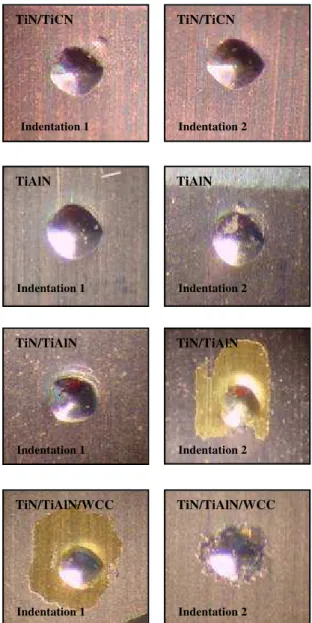
According to Fig. 9 (pictures with 40X enlargement), there were no cracks in the indentations made on the TiN/TiCN and TiAlN coated drills, which indicates that there was no delamination of the coating. For TiN/TiAlN coated drills there were circular cracks around indentation 1 and delamination for indentation 2. For TiN/TiAlN/WCC coated drills, there was delamination of the WCC and TiAlN coatings for indentation 1, exposing the TiN layer, and for indentation 2 there were small cracks and delamination of the WCC and TiAlN coating layers.
Indentations 1 and 2 for both TiN/TiCN and TiAlN coatings showed the same results. On the other hand, the way the coatings fractured was different between indentations 1 and 2 for both TiN/TiAlN and TiN/TiAlN/WCC. The results obtained in the Rockwell C indentation tests clearly show delamination of the TiAlN layer in the TiN/TiAlN and TiN/TiAlN/WCC drills, which indicates poor adhesion of that layer to the TiN base coating. Conversely, the indentations prove the good adhesion of the multilayer TiN/TiCN coating to the HSS substrate, which justifies its best performance in the life experiments.
Figure 9. Indentations after Rockwell C tests (40X enlargement).
500 µm
500 µm
500 µm
500 µm
TiN/TiCN
Indentation 1
TiN/TiAlN
TiN/TiAlN/WCC TiN/TiAlN/WCC
TiAlN TiAlN
Indentation 2 TiN/TiCN
Indentation 1 Indentation 2
TiN/TiAlN
Indentation 1 Indentation 2
Scratch Test with Progressive Load
Figure 10 shows the tangential force curve (Fx) obtained for the TiN/TiCN coating. The curves for TiAlN and TiN/TiAlN showed similar behaviour to the curve of TiN/TiCN. For these coatings, it was not possible to clearly identify a position during the "scratching" (distance travelled by the penetrator) that indicated evident signs of fluctuation of the force caused by the delamination of the coating. The quantification of the tangential force at which the adhesive failure of the film would happen is a difficult task. The coating-substrate duo behaves as a single mechanical system that reacts to deformations produced by external demands under service conditions (Franco Júnior, 2003), in this case the action of the penetrator. Because of this, mechanical failures of the duo can be of both cohesive nature (failures in the coating or in the substrate) and of adhesive nature (failures at the interface of the coating-substrate duo) (Franco Júnior, 2003). Both can lead to a premature damage of the coated tool.
As highlighted by the dashed circle in Fig. 11, for TiN/TiAlN/WCC it is possible to define a load at which there probably is a rupture between the coating and the substrate, as the penetrator "scratches" the surface of the tool. In this case, there probably is an adhesive failure of the WCC and TiAlN coatings at the beginning of the scratch, at approximately 1.5 mm of the distance travelled by the penetrator, as can be seen in Fig. 12.
Figure 10. Tangential force curve obtained for the TiN/TiCN.
Figure 11. Tangential force curve obtained for the TiN/TiAlN/WCC.
Figure 12. SEM images showing in detail the fracture of the WCC and TiAlN layers at the beginning of the "scratching" for TiN/TiAlN/WCC.
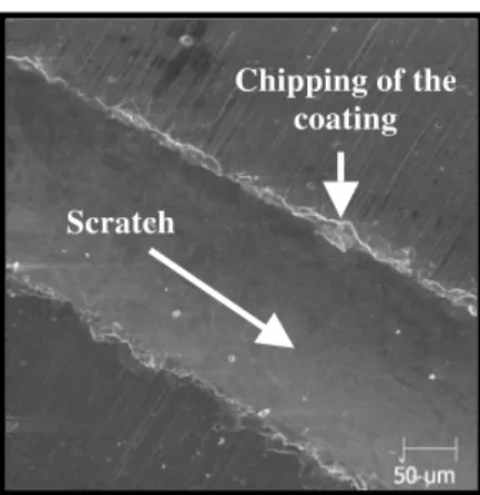
A common characteristic in all the tested coatings was the similar behaviour of the coatings with the progress of the penetrator. As the penetrator was deepened into the tool, the coating followed the deformation of the substrate, remaining adhered inside of the scratch produced. Only at the lateral borders of the scratch is that chipping and accumulation of small coating particles can be observed, Fig. 13.
Figure 13. SEM images showing the chipping of the TiN/TiCN coating.
Another quite peculiar phenomenon in this experiment happened with the tool coated with TiAlN: the "splintering" of the coating inside of the scratch. However, the splintered coating remained adhered to the substrate, as seen in Fig. 14.
TiN/TiCN
0 2 4 6 8 10
0 1 2 3 4 5
Distance traveled by the penetrator - [mm]
Tangential Force - [kgf]
TiN/TiAlN/WCC
0 2 4 6 8 10
0 1 2 3 4 5
Distance traveled by the penetrator - [mm]
Tangential Force - [kgf]
WCC
TiAlN
TiN
Scratch
1mm
Chipping of the
coating
Scratch
“Splintering” of the
coating
The different hardness values between the coating and the substrate of the tool induce the fracture of the coating, which, however, still remain adhered to the substrate. This evidence can justify the wear suffered by the TiAlN coated drills, since there was no delamination of the layer and, possibly, the coating was pulled out together with the substrate of the tool.
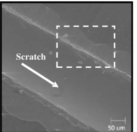
For the TiN/TiAlN and TiN/TiAlN/WCC coatings, a relevant characteristic was again the delamination of the TiAlN layer at the border of the scratch. Figure 15 shows this for the TiN/TiAlN coating. Figure 16 shows the detail for the region marked by the dashed rectangle in Fig. 15.
Figure 15. SEM images showing the delamination of the TiAlN layer at the border of the scratch.
Figure 16. SEM images showing the detail of the region marked in Fig. 15.
Although the results found in this experiment do not clearly establish a correlation between the load applied and the fracture of the coating, especially for the TiN/TiCN, TiAlN and TiN/TiAlN coatings, it was possible to notice that the good adhesion shown by TiN/TiCN was essential to its best performance in the life experiments. And these adhesion experiments showed the poor adhesion of the TiAlN layer used in the TiN/TiAlN and TiN/TiAlN/WCC coatings, which was decisive to the performance of the tools.
Conclusions
The results obtained in this work suggest the following conclusions:
• In this work the TiN/TiCN coating allowed the machining of the largest number of holes for the aluminium-silicon alloy ISO 3522 AlSi8Cu3Fe in the cutting conditions used.
• In the coatings TiN/TiAlN and TiN/TiAlN/WCC the adhesive failure of the TiAlN layer influenced in the performance of the tools during the machining.
• The results allowed establishing, partially, a link between coatings performance and the delamination of the coatings used in this work.
• In the Rockwell C indentation tests, there was delamination of the TiAlN layer for the TiN/TiAlN and TiN/TiAlN/WCC coatings in the given conditions tested.
• In the scratch tests with progressive load, it was not possible to clearly correlate the fracture of the coatings to the fluctuation of the tangential force.
Acknowledgements
The authors are grateful to CNPq, CAPES, FAPEMIG, Instituto Fábrica do Milênio and FIAT's Powertrain Technology for the financial and technical supports during the development of this work.
References
Bunshah, R.F., 2001, “Handbook of Hard Coatings-Deposition Technologies, Properties and Applications”, Noyes Publications, 550 p.
Cselle, T. and Barimani, A., 1995, “Today's applications and future developments of coatings for drills and rotating cutting tools”, Surface and
Coatings Technology, Vol. 76-77, pp. 712-718.
Franco Júnior, A.R., 2003, “Development of Duplex Coatings by Plasma Nitrating on AISI D2 and AISI H13 Tool Steels”, PhD Thesis, Universidade de São Paulo, SP, Brazil, 225p. (In Portuguese)
Karlsson, L., Hultman, L. and Sundgren, J.E., 2000, “Influence of residual stresses on the mechanical properties of TiCxN1–x (x = 0, 0.15, 0.45) thin films deposited by arc evaporation”, Thin Solid Films, Vol. 371, pp. 167-177.
Lima, M.S.F., Neves, D., Diniz, A.E., 2005, “Machining with a laser treated tool steel drill: surface and tool life aspects”, 1st International Conference on Heat Treatment and Surface Engineering of Tools and Dies, Pula-Croatia, 8-11 June.
Ollendorf, H. and Schneider, D., 1999, “A comparative study of adhesion test methods for hard coatings”, Surface and Coatings Technology, Vol. 113, pp. 86-102.
Polcar, T., Novák, R. and Siroky, P, 2006, “The tribological characteristics of TiCN coating at elevated temperatures”, Wear, Vol. 260, pp. 40-49.
Santos, S.C., Sales, W.F., Da Silva, F.J., Franco, S.D. and Da Silva, M.B., 2004, “Tribological characterization of PVD coatings for cutting tools”, Surface and Coatings Technology, Vol. 184, pp. 141-148.
Schneider, J.M., Voevodin, A., Rebholz, C., Matthews, A., Hogg, J.H.C., Lewis, D.B. and Ives, M., 1995, “X-ray diffraction investigations of magnetron sputtered TiCN coatings”, Surface and Coatings Technology, Vol. 74-75, pp. 312-31.
Tschiptschin, A.P., 2004, “Structure-properties relationship in hard coatings”, Metalurgia e Materiais, April, pp. 167-169. (In Portuguese)
Vancoille, E., Celis, J.P. and Roos, J.R., 1993, “Dry sliding wear of TiN based ternary PVD coatings”, Wear, Vol. 165, pp. 41-49.
Wei, C., Lin, J.F., Jiang, T.H. and Ai, C.F., 2001, “Tribological characteristics of Titanium Nitride and Titanium Carbonitride multilayer films: part I - the effect of coating sequence on material and mechanical properties”, Thin Solid Films, Vol. 381, pp. 94-103.