Residual Strength of a Steel-Concrete Composite Structure Subjected to a
Design Seismic Event Followed by Fire
Pedro NOGUEIRO
Adjunct Professor
Polytechnic Inst. of Bragança, Bragança, Portugal
Pedro Nogueiro, born 1971, received his civil engineering degree from the Univ. of Beira Interior in Covilhã, Portugal.
Aldina SANTIAGO
Research Assistant University of Coimbra Coimbra, Portugal
Aldina Santiago, born 1974, received his civil engineering degree from the Univ. of Beira Interior in Covilhã, Portugal.
Luís SIMÕES DA SILVA
Professor
University of Coimbra Coimbra, Portugal
Luís Simões da Silva, born 1962, received his civil engineering degree from FCTUC in Coimbra, Portugal.
Rita BENTO
Assistant Professor Instituto Superior Técnico Lisboa, Portugal
Rita Bento, born 1963, received his civil engineering degree from IST, Technical Univ. of Lisbon, Portugal.
Paulo VILA REAL
Professor
University of Aveiro Aveiro, Portugal
Paulo Vila Real, born 1960, received his civil engineering degree from FEUP in Porto, Portugal.
Summary
This paper presents a numerical investigation of the residual strength of a typical PR moment-resistant multi-storey steel framed structure, subjected to a design seismic event followed by fire. In order to allow a calibration with some real results from fire tests on a natural scale, the architectural and structural definitions of the eight-storey steel Cardington building were chosen as the reference case, adapted to deal with basic seismic requirements. The seismic action was simulated with an artificial accelerogram with PGA of 0.6g, chosen to achieve significant energy dissipation in the joints. The adopted fire event is limited to an isolated compartment and it is defined as the natural fire observed during a full-scale fire test carried out at the BRE. Finally, the results are discussed in terms of robustness requirements for extreme events.
Keywords: Earthquake, Fire, Connections, Steel structures, Extreme events, Buildings.
1.
Introduction
The possibility of fire following an earthquake is a major threat in seismic regions, as was observed on several historical great earthquakes: Lisbon 1755 (Fig. 1), San Francisco 1906 and 1989, Tokyo 1923 and Kobe 1995. Della Corte et al. [1] give an excellent summary of the main aspects resulting
from earthquakes that increase the risk of fires following earthquakes, as well as an increased risk of reduced safety against fire. It is also worth emphasizing that the losses resulting from fires developing soon after the earthquake may be compared to those resulting from the shaking [2]. Finally, the disruption caused by major earthquakes in the normal organization of the cities and the damage to the (non-structural) active measures to fight fires in buildings advise the use of performance-based approaches to evaluate the fire safety of structures taking into account the possibility of the previous occurrence of an earthquake.
Fig. 1. Lisbon damaged by earthquake and subsequent fire. (Copper engraving, Germany, 18th).
2.
Case Study: Eight Storey Steel Building
2.1 General Description
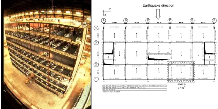
In order to allow calibration with real results from fire tests, the architectural and structural definitions of the eight-storey steel Cardington building were chosen as the reference case, adapted to comply with the Eurocode 8 seismic requirements. The steel building structure was built inside a former airship hangar located at Cardington, Bedfordshire, UK in the early 90’s. It is a steel framed construction using composite concrete slabs supported by steel decking in composite action with the steel beams. It has eight storeys (33 m) and is five bays (5×9 m) by three bays (6+9+6 m) in plan (Fig. 2a). The structure was built as a no-sway frame with a central lift shaft and two end staircases providing the necessary resistance against lateral wind loads. The main steel frame was designed for gravity loads, the joints consisting of flexible end plates for beam-to-column connections and fin plates for beam-to-beam connections, designed to transmit vertical shear loads. The building simulates a real commercial office in the Bedford area and all the elements were designed according to British Standards and checked for compliance with the provisions of the Structural Eurocodes. The building was designed for a dead load of 3.65 kN/m2 and an imposed load of 3.5 kN/m2 [3]. The floor construction consists of a steel deck and a light-weight in-situ concrete composite floor (LW35/40), incorporating a A142 (142 mm2/m) anti-crack mesh in both directions. The floor slab has an overall depth of 130 mm and the steel decking has a trough depth of 60 mm.
C3 254 254 89 UC All colums are in steel S355
C1 305 305 198 UC base to 2º floor/ 305 305 137 UC 2º floor to 5º floor / 254 254 89 UC 5º floor to roof C2 305 305 137 UC base to 4º floor / 254 254 89 UC 4º floor to roof
Level 4 77 m2 Y 3 5 6 1 7 1 51 U B (S 355) 3 5 6 1 7 1 51 U B (S 355)
305 165 40 UB (S275) 356 171 51 UB (S355)
9.0 m 9.0 m 9.0 m 9.0 m 9.0 m 9.0 m 9.0 m 9.0 m 9.0 m
9.0 m 9.0 m9.0 m9.0 m9.0 m9.0 m 9.0 m 9.0 m 9.0 m 9.0 m 9.0 m 35 6 1 71 51 U B (S 355) 35 6 1 71 51 U B (S 355) E
C2 356 171 51 UB (S355) C3 F C2 C2 356 171 51 UB ( S 355 ) 3
56 171 51 UB
(S
355)
356 171 51 UB (S355) 305 165 40 UB (S275)
C2
356 171 51 UB (S355)
C2 35 6 1 71 51 U B ( S 3 55)
356 171 51 UB (S355)
35 6 1 71 51 U B (S 355) D
356 171 51 UB (S355)
C2
C
C2 356 171 51 UB (S355)
C1 305 165 40 UB (S275)
C1 3 56 17 1 5 1 U B ( S 355 )
C1 356 171 51 UB (S355)
C1
356 171 51 UB (S355)
C1
356 171 51 UB (S355)
C1
B
C2 356 171 51 UB (S355) A
356 171 51 UB (S355)
C3 9.0 m 9.0 m 9.0 m 9.0 m 9.0 m
C1 305 165 40 UB (S275)
61 0 2 29 10 1 U B ( S 327 ) C2
356 171 51 UB (S355)
C2
356 171 51 UB (S355) 356 171 51 UB (S355)
356 171 51 UB
( S 355 ) 35 6 1 71 51 U B ( S 3 55)
305 165 40 UB (S275)
35 6 17 1 5 1 U B ( S 35 5) 3 5 6 1 7 1 51 U B (S 355) 3 56 17 1 5 1 U B ( S 355 ) C1 61 0 2 29 10 1 U B ( S 275 ) C1 35 6 17 1 51 U B (S 355) C2 35 6 1 71 51 U B ( S 3 55)
305 165 40 UB (S275)
356 171 51 UB (S355)
C3
305 165 40 UB (S275)
356 171 51 UB (S355)
C2
356 171 51 UB (S355) 305 165 40 UB (S275)
C2
356 171 51 UB (S355)
35 6 1 71 51 U B (S 355)
305 165 40 UB (S275)
C3
356 171 51 UB (S355)
356 17 1 5 1 U B ( S 35 5) 35 6 1 71 51 U B (S 355) C1 356 17 1 5 1 UB ( S35 5) 4 3 6. 0 m 1 6. 0 m 9. 0 m 2 C2 C2 C2 X C1 C2 C2 Earthquake direction
2.2 Fire Compartment
The fire compartment was situated in the middle of the building enclosing a plan area of 11×7 m2, on the 4th floor, with a ceiling height of 4.185 m (Fig. 2b). A ventilation opening with 10.4×1.27 m2 is located as shown in Fig. 2. The walls consist of plasterboard plates (thermal conductivity k=0.24 W/(mK)) with 0.0425 m thickness. Ceiling and floor are made of concrete (k=0.7 W/(mK)) with 0.11 m thickness. As recommended by Buchanan [2], the columns and external joints and beam (approximately 1.0 m from the joint) were heavily protected. The material protection used was 15 mm of Cafco300 vermiculite-cement spray, with k=0.078 W/mK.
3.
Seismic Response
3.1 Numerical Study: Assumptions
The original Cardington structure was designed as a braced frame, with 3 rigid lift and staircase vertical modules, using diagonal bracings that absorb the horizontal forces. In order to evaluate the influence of the partial strength joints in the energy dissipation, the bracings were removed in the X-direction (Fig. 2b), that corresponds to the major axis of the columns. Using the actual layout and geometrical definition of the flush end-plate beam-to-column joints, the strength and initial stiffness was evaluated using the component method [4]. Subsequently, the hysteretic behaviour of the joints were defined following Nogueiro et al. [5]. Mrd denotes the resistance of the joint equal to 75 KNm,
Ki is the initial stiffness equal to 25000 KNm/rad, Kp represents the post-limit stiffness, equal to
750 KNm/rad and iM denotes the strength degradation coefficient considered equal to 0.6. The
structure was subjected to an artificial accelerogram with PGA=0.6g, generated to match the elastic response spectrum present in Eurocode 8, for subsoil class B, with 10 seconds of stationary part and 30 seconds of duration. A peak ground acceleration of 0.6g was selected in order to obtain meaningful dissipative behaviour in the joints. The SeismoStruct program [6] was used for the seismic analysis.
3.2 Frequencies and Modes of Vibration
The dynamic characteristics, related to the adopted earthquake direction (Fig. 2b), were evaluated for the three-dimensional (3D) structure and one two-dimensional (2D) internal frame E (Fig. 3 a). The 3D structure presents a first natural frequency of 0.41 Hz, while frame E shows an equivalent value of 0.31 Hz, both in good agreement. The structure is very flexible, a direct consequence of the PR joints. Fig. 3 b) illustrates the first mode of vibration for the 3D structure and Fig. 3 c) illustrates the first mode of vibration for frame E.
Floor 8
Floor 7
Floor 5 Floor 6
Floor 3 Floor 4
Floor 2
Floor 1
Ground Floor
6.0 m 4.5 m 6.0 m 4.5 m
4 3 2 1
4.135m 4.135m 4.135m
4.135m 4.135m 4.135m
4.135m
4.335m Z
X
J62
E
F
a) b) c)
Fig. 3. a) Frame E; First mode of vibration, b) 3D structure; c) Frame E.
3.3 Non-linear Dynamic Analysis
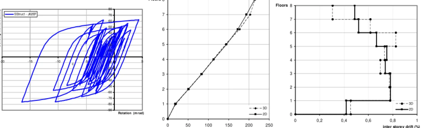
seismic strength and stiffness degradation. Because the beams are composite, with a moment resistance much higher than the resistance of the joints, the mechanical damage is mainly due to non-linear behaviour of the connections. The results show that the most stressed connections are located in the 5th floor, the same floor where the fire compartment is located. These connections exhibit approximately 50% of strength deterioration, as can be seen in Fig. 4a, and a energy dissipation of 4.87 KNm×rad. Figures 4b and 4c show the distribution with height of the maximum values of storey displacements and interstorey drifts, respectively. The maximum values obtained in the step by step procedure for both structures are very similar, as expected due to the symmetry and the uniform distribution of structural elements in plan in the 3D structure. The maximum values of displacements and inter-story drifts occur for the stiffer 3D structure.
-90 -80 -70 -60 -50 -40 -30 -20 -10 0 10 20 30 40 50 60 70 80
-20 -15 -10 -5 0 5
Rotation (m rad)
B
e
ndi
n
g M
om
e
nt
(
k
N
m
)
SStruct - J62EF
c
0 1 2 3 4 5 6 7 8
0 50 100 150 200 250
Maximum displacements (mm) Floors
3D 2D 0
1 2 3 4 5 6 7 8
0 0,2 0,4 0,6 0,8 1
inter storey drift (%) Floors
3D 2D
Fig. 4. a) Hysteretic curve for joint J62EF; b) Horizontal displacements; c)Inter-story drifts.
Fig. 5 shows the time histories for bending moment and rotation of the selected joint, that exhibits the maximum values of internal forces. Fig. 5 also shows that the maximum values of bending moment occur in the first 10 seconds, mainly due to the characteristics of the chosen accelerogram. The maximum value of rotation occurs after about 7.5 seconds, where some strength degradation is
lready noticed. a
-80 -70 -60 -50 -40 -30 -20 -10 0 10 20 30 40 50 60 70
0 5 10 15 20 25 30
Time (sec)
B
e
nd
in
g M
o
m
e
nt
(
K
N
m
)
J62EF
-0,02 -0,01 0,00 0,01
0 5 10 15 20 25 30
Time (sec)
R
ot
a
ti
on (
m
ra
d)
J62EF
Fig. 5. Time-history results for joint J62EF a) Bending moment; b) Rotation.
3.4 Damage Assessment
4.
Fire Response
4.1 Assumptions and Numerical Modeling
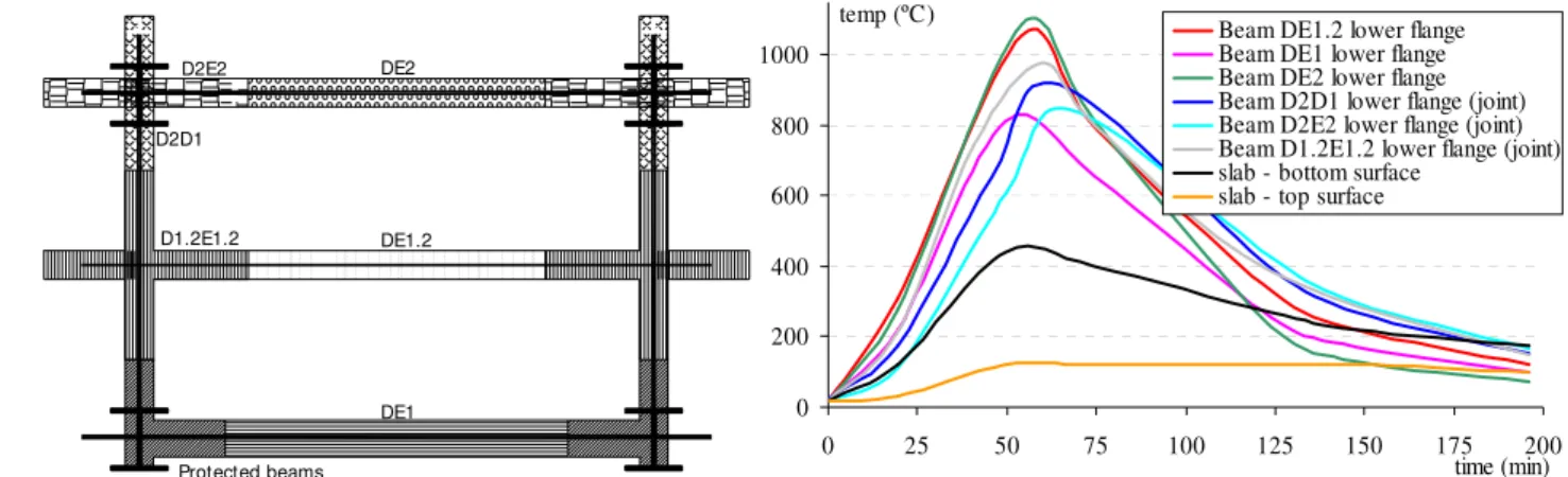
Following the earthquake, it is assumed that fire occurs in a confined compartment at the 4th floor of the building. This choice was dictated by the possibility of comparison with a natural fire experiment carried out in the Cardington building, as already explained above. To allow for a detailed assessment of the structural response under fire, a sub-structure was considered where all the major deformation would occur. The corresponding structural model is illustrated in Fig. 6. The fire loading corresponds to the results measured during the full-scale natural fire test [3]. It was applied directly to the steel beams and composite slab as a time-temperature curve. In the beams, the temperature varies along the length and within the cross-sections (a maximum gradient of 200ºC is applied within the cross-section at the beam mid-span that decreases to zero near the joints); in the slab a temperature variation within the cross-section was also considered; finally, the protected beams and columns were assumed to remain at room temperature (Fig. 7).
The numerical analysis of the sub-structure was performed with the finite element code LUSAS [7]. Three-dimensional thin beam elements were employed in the simulation of the steel beams and columns, compatible joint elements modeled the beam-to-beam and beam-to-column connections and three-dimensional eight-noded thin shells elements were used to model the composite slab (Fig. 6). The analysis was performed considering geometrical (Total Lagrangian formulation) and material nonlinearities (Newton-Raphson method). A von Mises material model was used to model the steel members and the composite slab. A nonlinear joint model was chosen for the joint elements. The material properties assumed for the joint model were the following: Ke,axial = 1E5
kN/m, Nrd = 400 kN, Kpl,axial = 100 kN/m, Ke,rot = 1000 kNm/rad, Mrd = 20 kNm, Kpl,rot = 3 kNm/rad
(beam-to-beam connections); Ke,axial = 1E5 kN/m, Nrd = 400 kN, Kpl,axial = 100 kN/m, Ke,rot = 12500
D E
5th floor
4th floor 2
1
Fire
compartment 3rd floor
Fig. 6. Finite element mesh: a) plan view; b) front view
D2E2
D2D1
D1.2E1.2
DE1 DE1.2 DE2
Protected beams
0 200 400 600 800 1000
0 25 50 75 100 125 150 175 200
time (min)
temp (ºC) Beam DE1.2 lower flange
Beam DE1 lower flange Beam DE2 lower flange Beam D2D1 lower flange (joint) Beam D2E2 lower flange (joint) Beam D1.2E1.2 lower flange (joint) slab - bottom surface
slab - top surface
kNm/rad, Mrd = 30 kNm, Kpl,rot = 35.5 kNm/rad (major and minor axis beam-to-column
connections). These values are representative of the residual properties of the joints after the earthquake. The composite slab, steel beams and steel columns material properties are non-linearly temperature dependent, according to EN 1993-1-2 [8] and EN 1994-1-2 [9]. The effect of creep deformations of steel has been considered indirectly through the use of the conventional stress-strain-temperature relationship suggested by EN1993-1-2 [8].
4.2 Analysis of the results
4.2.1 Behaviour of the Structural Members
Fig. 8 shows the maximum vertical deformation contours for the 5th floor (0.78 m) and compares the development of the vertical displacements in the structural elements. Examination of the secondary beams shows that during the heating phase, the beam with the lower displacement is the beam near the window, because of lower temperatures, while the beam at the centre of the compartment shows the biggest displacement. In the cooling phase, the deflection of these beams remains constant, while the internal beam DE2 presents some partial elastic recovery. The dotted line in Fig. 8b illustrates the usual failure deflection limit state of L/30.
-0.8 -0.7 -0.6 -0.5 -0.4 -0.3 -0.2 -0.1 0.0
0 25 50 75 100 125 150 175 200
t (m in)
d
z
(m
)
m axim um deflection L/ 30
beam D1.2-E1.2 beam DE1 beam DE2
Fig. 8. a) Maximum vertical displacement contour for the 5th floor; b) Vertical displacement.
4.2.2 Behaviour of the Joints
Fig. 9a shows the development of the axial force in the joints throughout the fire and Fig. 9b shows the corresponding variation of the axial force versus axial displacement. It is observed that throughout the fire development the axial force does not exceed the residual axial force in the joints, hinting that these joints might survive the fire event. Fig. 9c compares the development of the bending moment on joint and beam mid-span and Fig. 9d shows the development of the joint bending moment versus joint rotation. It is observed that joint yields just starting the fire;
-120 -60 0 60 120 180 240 300 360
0 25 50 75 100 125 150 175 200
t ( m in)
N
x
(
K
N
)
fin-plate D12 - left
fin-plate D12 - rigth
-120
-60 0 60 120 180 240 300 360
-0.002 -0.001 0.000 0.001 0.002 0.003 0.004
dx (m )
N
x
(
k
N
)
-100 -80 -60 -40 -20 0 20
0 25 50 75 100 125 150 175 200
t (m in)
M
y
(
K
N
)
fin-plate D12 - left fin-plate D12 - rigth m id-span beam DE12
0 4 8 12 16 20
0.000 0.008 0.016 0.024 0.032 0.040 0.048 0.056 0.064
θy (rad)
M
y
(
k
N
m
)
fin-plate D12 - rigth
fin-plate D12 - rigth
Fig. 9. Fin plate D1.2.
Fig. 10a shows the development of the axial force in the joint throughout the fire and Fig. 10b shows the corresponding variation of axial force versus axial displacement. It is observed that during the cooling phase the measured axial force exceeds the seismic residual axial force, showing failure of the connection from the tensile components (such as bolts or end-plates) because of high cooling strains. Fig. 10c shows the development of the joint bending moment and Fig. 10d shows the variation of bending moment versus joint rotation. It is observed that the joint yields after 20 min.; the joint rotation reaches extremely high values, clearly in excess of the available ductility.
-60 0 60 120 180 240 300 360 420
0 25 50 75 100 125 150 175 200
t (m in)
N
x
(K
N
)
D2 - left
D2 - rigth
0 60 120 180 240 300 360 420
0.000 0.001 0.002 0.003 0.004 0.005 0.006 0.007 0.008
dx (m )
N
x
(k
N
)
D2 - rigth
0 5 10 15 20 25 30 35
0 25 50 75 100 125 150 175 200
t (m in)
M
y
(
K
N
)
D2 - left
D2 - rigth
0 5 10 15 20 25 30 35
0.00 0.02 0.04 0.06 0.08 0.10 0.12 0.14 0.16
θy (rad)
M
y
(
k
N
m
)
D2 - rigth
Fig. 10. Header plate – minor axis D2.
5.
Concluding Remarks
structure. The ductility and energy dissipation of the structure was concentrated on the major axis partial strength joints. The seismic event resulted in significant strength of these joints, close to the threshold of 50% strength degradation that is usually taken as the low-cycle fatigue limit. The available ductility of the joints was apparently insufficient to avoid structural collapse because of fire. These conclusions reinforce the viewpoint [1] that the fire resistance performance should be taken into account considering also the earthquake-induced damage for buildings in seismic areas and adequate robustness reserve should be present in such circumstances.
6.
Acknowledgements
Financial support from the Portuguese Ministry of Science and Higher Education (Ministério da
Ciência e Ensino Superior) under contract grants from PRODEP III (5.3) for Pedro Nogueiro is
gratefully acknowledged. Financial support from the Portuguese Ministry of Science and High Education (Ministério da Ciência e do Ensino Superior) under FCT research project POCI/ECM/55783/2004 is acknowledged.The assistance provided by Seismosoft, is also most appreciated (http://www.seismosoft.com).
References
[1] DELLA CORTE G., FAGGIANO B. and MAZZOLANI F., "On the structural effects of fire following an earthquake", in Schaur, C., Mazzolani, F., Huber, G., de Matteis, G., Trumpf, H., Koukkari, H., Jaspart, J.-P. and Bragança, L. (eds.), Improvement of Building’s Structural
Quality by new Technologies - COST C12 Final Conference Proceedings, Taylor and Francis,
London, 2005, pp. 359-367.
[2] BUCHANAN A.H., Structural Design for Fire Safety, John Wiley & Sons, Chichester,
England, 2001.
[3] WALD F., SIMÕES DA SILVA L., MOORE D.B., LENNON T., CHLADNÁ M., SANTIAGO A., BENEŠ M., and BORGES L., “Experimental Behaviour of a Steel Structure under Natural Fire”, New Steel Construction13(3), 2005, pp. 24-26.
[4] EN 1993-1-8: 2004. Eurocode 3: Design of steel structures. Part 1.8: Design of Joints,
European Committee for Standardization (CEN), Brussels, 2004.
[5] NOGUEIRO P., SIMÕES DA SILVA L., BENTO R. and SIMÕES R., “Numerical implementation and calibration of a hysteretic model with pinching for the cyclic response of steel and composite joints”, Proceedings of the 4th International Conference on Advances in
Steel Structures ICASS’05, Elsevier, Shangai, China, 2005 (in print).
[6] SEISMOSTRUCT, "Computer program for static and dynamic nonlinear analysis of framed structures" [online], 2004. Available from URL: http://www.seismosoft.com
[7] LUSAS 13. Theory Manual, FEA Ltd, V.13.5. Surrey, UK, 2003.
[8] EN 1993-1-2: 2004. Eurocode 3: Design of steel structures. Part 1.2: General rules –
Structural fire design, European Committee for Standardization (CEN), Brussels, 2004.
[9] EN 1994-1-2: 2004. Eurocode 4: Design of composite steel and concrete structures. Part 1.2: