UNIVERSIDADE DA BEIRA INTERIOR
Engenharia
Development of an Efficient Propulsion System
for a Battery Electric Shell Eco Marathon
Prototype Vehicle
Versão final após defesa
Jorge Miguel Guedes Rebelo
Dissertação para obtenção do Grau de Mestre em
Engenharia Aeronáutica
(Ciclo de estudos integrado)
Orientador: Prof. Doutor Miguel Ângelo Rodrigues Silvestre
iii
Dedication
The author dedicates his dissertation work to his family and many friends. A special feeling of gratitude to his loving parents, Rui and Maria José whose words of encouragement and push for tenacity ring in his ears. His sister Catarina, have never left his side.
The author also dedicates this dissertation to his many friends and work colleagues who have supported him throughout the process. The author always appreciated all they have done, especially professor Miguel Silvestre for helping the development of the author’s theoretical and practical skills.
The author dedicates this work and give special thanks to his girlfriend for being there throughout the entire master program.
v
Acknowledgements
The author would like to thank Professor Miguel Silvestre for supervising, for his suggestions and guidelines through this project. this project would not have been possible without his knowledge and skills.
The author is also thankful to all professors for their dedication to quality engineering instruction, for serving on his graduate committee, and for tying up the ends of the degree on such short notice.
And to all team members of Aero@UBI team for the team-work and experiences shared during this project.
The author would also like to thanks to everyone involved for being patient, understanding, and willing to work with him through the tough spots and delays in the work as well as those in his own life.
Last but not the least, the author would like to thank to the “Top Team” from Heliportugal for giving the permission and the time for the accomplishment of this thesis and encouragement, as well.
vii
Resumo
Para a participação da equipa Aero@Ubi na competição da Shell Eco-marathon, um motor elétrico de imanes permanentes, sem núcleo ferromagnético, foi desenhado, construído e testado. Este tipo de motor é caracterizado por ter uma baixa indutância e baixa resistência elétrica o que provoca picos de corrente quando acionado. Para resolver este problema, e também como requisito do regulamento da prova um controlado deve ser desenvolvido. Neste caso, foi desenvolvido, construído e testado um controlador com uma comutação de 60 graus.
Palavras-chave
Motor elétrico, magnetos permanentes, sem ferro, controlador de motor, comutação de 60 graus.
ix
Abstract
For the participation of the Aero@UBI team in Shell Eco-Marathon competition an in-wheel electric, ironless brushless permanent magnet motor was designed and build, this type of motors is characterized by very inductance and a very low resistance between phases which leads to current ripple, to solve this problem, and also, as Shell Eco-marathon competition requirements, a controller must be developed. In this case a controller with a 60-degree commutation was implemented and tested.
Keywords
xi
Table of Contents
Chapter 1 ... 1 1.1. Motivation 1 1.2. Scope 2 1.3. Objectives 2 1.4. Dissertation structure 3 Chapter 2 ... 52.1. Definitions and types of brushless motors 5
2.1.1. Basic Terminology 5
2.1.2. Motor Losses and Efficiency 7
2.1.3. Back Electromotive Force and Torque Production 7
2.2. Motor Controllers 8
2.2.1. Three Phase Motor Commutation Scheme 9
2.2.1.1. Trapezoidal Commutation 9
2.2.1.2. Sinusoidal Commutation 10
2.2.2. Phase Current Level Control 11
2.2.2.1. PWM Current Control 11
2.2.2.2. Hysteretic Phase Current Control 13
2.2.2.3. Multilevel Inverter for Phase Current Control 13
2.2.2.4. Field Oriented Control 16
2.3. State of the Art 17
2.3.1. PMSM Electrical Machines 17 2.3.2. Motor Controller 20 Chapter 3 ... 23 3.1. Motor Development 23 3.1.1. Conceptual Design 23 3.1.2. Preliminary Design 28 3.1.3. Detailed Design 34 3.1.4. Fabrication 35 3.1.4.1. Stator 35
3.1.4.2. Rotor Manufacture Process 37
3.1.4.3. Stator Support 37
3.1.4.4. Wheel/Motor Hub 38
3.1.5. Motor Testing 39
3.1.5.1. Back Electromotive Force 39
3.1.5.2. Motor Mechanical Losses Measurements 39
3.1.5.2.1. Motor Rotor’s Moment of Inertia Measurements 39
3.1.5.2.2. Mechanical Losses Measurement 40
xii
3.2.1. Conceptual design 40
3.2.2. Circuit Design and Component Selection 43
3.2.2.1. Half-Bridge Module 43
3.2.2.1.1. Gate Drive Optocoupler 43
3.2.2.1.2. Shoot-Through Protection 44
3.2.2.1.3. MOSFET 45
3.2.2.1.4. Bootstrap 46
3.2.2.1.5. Bus Capacitor 46
3.2.2.2. Current Sensor and Comparator Module 46
3.2.2.2.1. Current Sensor 47
3.2.2.2.2. Current Comparator 47
3.2.2.3. PLD Module 47
3.2.2.3.1. Motor Position 48
3.2.2.4. Capacitor Bank Module 48
3.2.3. Implementation 48
3.2.3.1. Half-Bridge Module 49
3.2.3.2. Current Sensor and Comparator Module 50
3.2.3.3. PLD module 51
3.2.3.3.1. Motor Position Sensors 52
3.2.3.4. Capacitor Bank Module 52
3.2.4. Controller Testing 53
3.2.4.1. Current Limiting Function 53
3.2.5. Controller and Motor Testing 54
3.2.5.1. No Load Current 54
3.2.5.2. Loaded System Testing 54
3.2.5.3. Load Testing with TI C2000 and DRV8301Controller 55 Chapter 4 ... 57
4.1. Motor Testing 57
4.1.1. Back Electromotive Force 57
4.1.2. Motor Mechanical Losses 58
4.1.2.1. Motor Rotor’s Moment of Inertia 58
4.1.2.2. Motor Mechanical Losses Measurement 59
4.2. Controller Testing 59
4.2.1. Current Limiting Function 59
4.3. Controller and Motor Testing 60
4.3.1. No Load Current 60
4.3.2. Load Current 61
4.3.3. Load TI C2000 and DRV8301 62
4.3.4. SEM Vehicle Prototype on Track Performance 63 Chapter 5 ... 65
xiii
Figure list
Figure 1 - Aero@UBI01 in SEM 2015 competition run 1
Figure 2 - Basic permanent magnet synchronous motor 5
Figure 3 - Motor configurations: radial flux inrunner rotor, radial flux outrunner rotor and
axial flux disk rotor 6
Figure 4 – Sinusoidal and trapezoidal BEMF waveforms [3] 8
Figure 5 - Typical Controller architecture 9
Figure 6 – Current path on a trapezoidal commutation [4] 10 Figure 7 – Current path on a sinusoidal commutation [4] 10
Figure 8 - Typical analog PWM Inverter 12
Figure 9 - Typical Hysteresis Current Controller [5] 13 Figure 10 - Multilevel Inverter Output [6] a) two-level inverter, b) three-level inverter and c)
nine-level inverter. 14
Figure 11 – Multilevel inverter representation with: two levels a), three levels b), and n
levels c)[7] 14
Figure 12 – Three-level inverter: a) basic circuit; b) implemented in a diode clamped
topology; c) implemented in a flying capacitor topology adapted from [7] 15
Figure 13 - Castaded half-bridge inverter [7] 16
Figure 14 - Field Oriented Control Implementation [8] 16 Figure 15 -Field Oriented Control Implementation [9] 17
Figure 16 - Motor CSIRO [12] 18
Figure 17 - LaunchPoint’s Electric Motor [14] 19
Figure 18 - Layout of the motor drive control system presented by Caricchi et al [10] 21
Figure 19 - Wave winding concept 26
Figure 20 - Motor axial flux coreless motor concept 26
Figure 21 - Motor section concept 27
Figure 22 - First motor concept design. 27
Figure 23 - Motor stator copper mass due to pole count in function of design point efficiency 33 Figure 24 - Motor mass versus design point efficiency. 33
Figure 25 - Final motor design 35
Figure 26 - Stator design 35
Figure 27 - Phase winding markings 36
Figure 28 - Stator fabrication before pouring the epoxy resin. 36 Figure 29 - Rotor fabrication – placing the magnets 37
Figure 30 - Stator Support 38
xiv
Figure 32 - Moment of Inertia Measurement: Test rig schema to measure the motor rotor’s
moment of inertia. 40
Figure 33 - Graphical representation of the 60-degree commutation scheme 42
Figure 34 – First controller concept design 43
Figure 35 - Shoot-through protection circuit 44
Figure 36 - Electrical symbol of an N-channel and P-channel MOSFETs 45
Figure 37 - Bootstrap Operation 46
Figure 38 - Half-Bridge Module Schematic 49
Figure 39 - Half-Bridge Module board layout(left) and built(right). 49 Figure 40 -Current Sensor and Comparator Module Schematic. 50 Figure 41 -Current Sensor and Comparator Module layout(left) and built(right). 50
Figure 42 - PLD Module Schematic. 51
Figure 43 - PLD module layout(left) and assembled(right) 51
Figure 44 – Hall Effect Sensors positioning. 52
Figure 45 - Capacitor Bank Assembled 53
Figure 46 – Motor-Controller system test rig schematic. 53 Figure 47 - Schematic of the test bench used for load measurements 54
Figure 48 - BEMF measurement 57
Figure 49 - Measured voltage waveform vs sinusoidal waveform 58 Figure 50 - Motor of inertia measurement test rig according to section 3.1.5.2.1 58
Figure 51 – Current limiting function measurements 60
Figure 52 - No load current measurement 60
Figure 53 - Motor-Controller system efficiency experimental results with no load 61
Figure 54 – Load current measurement 61
Figure 55 - Motor-Controller system efficiency experimental results of the designed controller 62 Figure 56 - Motor-Controller system efficiency experimental results comparison between TI
xv
Table list
Table 1 - Switching sequence for trapezoidal commutation 10 Table 2 - Switching sequence for sinusoidal commutation 11
Table 3 - Motor requirements 24
Table 4 – Motor Parameters 34
Table 5 - Switching sequence for 60-degree commutation 42 Table 6 - Specifications for the Avago ACPL-H342 Optocoupler 44 Table 7 - Specifications for the AUIRFS8409-7P N-channel MOSFET 45
Table 8 - ACS770-50U IC specifications 47
Table 9 - Rotor's moment of inertia measurements 59
xvii
List of Abbreviations
3D Three-dimensional AC Alternating Current
AFPM Axial Flux Permanent-Magnet BEMF Back Electromotive Force BLDC Brushless Direct Current CAD Computer-Aided Design CNC Computer Numeric Control
CSIRO Commonwealth Scientific and Industrial Research Organization DC Direct Current
EMF Electromotive Force FOC Field Oriented Control GND Ground
IGBT Insulated-Gate Bipolar Transistor MsC Master of Science
MOSFET Metal–Oxide–Semiconductor Field-effect Transistor PCB Printed Circuit Board
PM Permanent Magnet
PMSM Permanent Magnet Synchronous Motor PMG Permanent Magnet Generator
PLA Polylactic Acid
PLD Programmable Logic Device PWM Pulse-Width Modulation RC Radio Controlled rpm Revolutions per minute SEM Shell Eco-marathon TI Texas Instruments TTL Transistor–transistor logic VCC Positive Supply Voltage VDC Voltage in Direct Current Bus
xix
List of Symbols
𝐴 Wave winding coil area subjected to the magnetic flux 𝐴𝑁 Minimum copper coil wire section area
𝐴𝑆 Stator disk area
𝐵𝑐𝑜𝑖𝑙 Flux density at the stator 𝐵𝑚𝑎𝑔 Flux intensity of the magnets
𝐶𝑠 Shoot-through Capacitor capacitance 𝑑 Direct axis
𝑑𝑤𝑖𝑟𝑒 Minimum copper wire diameter 𝐹𝐹 Stator filling factor
𝑔 Distance between opposing magnets faces 𝐼 Moment of inertia
IA Current on phase A
IB Current on phase B
IC Current on phase C
𝐼𝐴𝐵𝐶𝑟𝑚𝑠 Motor phase current
𝐼𝑟𝑚𝑠 Motor current rms 𝐾𝑡 Motor constant
𝐿 Inductance
𝐿𝑚𝑎𝑔 Magnet pole length 𝑙𝑁 Total wire length per coil 𝑙𝑝 Length of coil wire per turn
𝑚𝑤𝑖𝑟𝑒 Motor stator copper mass for the required copper volume per phase 𝑚𝑚𝑎𝑔 Stator magnets mass
𝑁 Required turns per coil 𝑃 Magnet poles number 𝑃𝑐 Shaft Power
𝑃𝑐𝑒 Motor electrical power 𝑝𝑒𝑟 Motor stator mean perimeter 𝑝𝑒𝑟𝑖𝑛 Stator inner perimeter 𝑝𝑒𝑟𝑜𝑢𝑡 Stator outer perimeter
𝑞 Quadrature axis 𝑅 Winding resistance 𝑅𝑚𝑎𝑔 Radius at magnets
𝑅𝑠 Current-limiting resistor
𝑡𝑑𝑒𝑙𝑎𝑦 Shoot-through protection time delay 𝑡𝑚 Magnet thickness
xx
𝑡𝑚𝑎𝑔 Duration of the coil motion from one magnet to the next 𝑡𝑠 Stator thickness
𝑈 Voltage applied to the motor 𝑈𝐴𝐵𝐶 Maximum phase voltage 𝑈𝐴𝐵𝑟𝑚𝑠 AC tension rms
𝑈𝑏𝑒𝑚𝑓𝑟𝑚𝑠 Required motor effective back electromotive force
UDC Voltage of the DC bus
𝑈𝑒𝑚𝑓 Motor back electromotive force
Ursw Reference sinusoidal wave signal
Utw Triangular wave signal in the negative terminal
VDC+ Positive voltage of DC bus
VDC- Negative voltage of DC bus
𝑉𝑓 Optocoupler led forward voltage 𝑉𝑠𝑖𝑔 Voltage input in half-bridge
𝑉𝑤𝑖𝑟𝑒 Minimum copper volume per phase 𝑊 Magnet pole width
𝜂𝑐 Motor Efficiency 𝜙 Magnetic flux
𝜃
Angle corresponding to half electric revolution 𝜔 Angular speed1
Chapter 1
1. Introduction
1.1.
Motivation
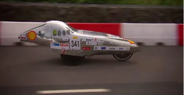
Shell Eco-marathon (SEM) is a global competition that challenges student teams around the world to design, build, test and drive ultra-energy-efficient vehicles, this competition is divided in three events by the locations of the teams (Europe, Asia and Americas). There are two categories: Urban Concept and Prototype, in both categories the car design and features have some limitations, such as maximum dimensions, a purpose-built motor controller and safety features.
Although, Aeronautical Engineering students, normally deal with aircraft stuff and therefore University of Beira Interior (UBI) participated and won the Air Cargo Challenge 2011, we felt that we can bring some of our aircraft's design and build expertise into the SEM competition. In September of 2013, it was decided to apply for the European edition with a Prototype and thus, we started to gather some ideas and concepts for the design of our car. In January, we had the confirmation that the participation application was accepted and the Aero@UBI team from UBI was created and started the work on de Aero@UBI01 SEM prototype car. The same car was used in the 2014 through 2017 SEM editions. Figure 1 shows the Aero@UBI01 car from 2015 running for the Shell Eco-marathon score completion.
2
1.2.
Scope
With the participation in SEM, an opportunity was created to design, built and test an efficiency optimized electric motor and controller set from scratch, this was a great opportunity to explore a leading-edge field of study, because efficient electric propulsion is currently in the spot light, from a hobby RC Quadcopter to a road legal Electric Vehicle.
The goal of this Thesis is the development construction of an ultra-efficient propulsion system for the Aero@UBI01 SEM prototype. Since, on one hand, the motor efficiency is highly dependent on the controller ability to correctly supply the appropriate waveform that maximizes the working motor efficiency. On the other hand, if all effort would be put into supplying the correct waveform, the controller itself could suffer from excessive switching losses. Additionally, as part of the Shell Eco-marathon requirements the motor controller had to be purpose built. For all these reasons, the current work is dedicated to both the motor and the controller such that the whole propulsion system can be as efficient as possible.
1.3.
Objectives
The purpose of this work was to develop an in-wheel direct-drive permanent motor and respective controller for the Aero@UBI car, to do so it was necessary to:
• do a literature review to check that this was the best motor type and configuration for our purpose;
• develop a formulation to model the motor;
• identify the design parameters affecting the motor efficiency; • implement it in a computer model to predict the motor performance; • perform a parametric study to select a design point;
• design the motor in detail in a 3D CAD environment;
• fabricate the motor in-house using fast prototyping CNC technology;
• test the motor with a commercial controller and with the in-house developed controller.
At the same time the work on the controller included: • a literature review about motor controllers;
• select the best control strategy for the type of motor being developed; • implement the control in an appropriate circuit;
• select the electronic components; • design and build the PCB;
• assemble the controller;
3
1.4.
Dissertation structure
Beyond the present introductory chapter, this dissertation is organized into the following chapters:
• Chapter 2 presents the literature review on both the motor and the controller. It includes a review on the basic principles of operation followed by the state of the art. • Chapter 3 presents the methodology that was implemented for the motor development
in the first part and for the controller in the second part. • Chapter 4 is where the results are presented and discussed;
• Chapter 5 is a summary of the conclusions and presents recommendations for future work.
5
Chapter 2
2. Literature Review
This chapter will first cover the basic principles of electric motors and controllers. In respect to the first topic, the focus is narrowed to the permanent magnet synchronous motor (PMSM) since it was found to be the potentially most efficient motor type for our purpose. Next, the focus changes for the controller: describing the possible control strategies. Finally, the state of the art in the ultra-efficient electric propulsion will be presented, regarding both the electrical machine and the controller.
2.1.
Definitions and types of brushless motors
As the name suggests, a brushless motor is a motor without brushes, slip rings or any other mechanical commutators, like it would be used in a conventional DC motor. Brushless DC motors are normally characterized by having a trapezoidal back electromotive force (BEMF) and are normally driven by rectangular pulse currents. PMSM differ from brushless DC motor in that they typically have a sinusoidal BEMF and are driven by sinusoidal currents. In reality, both brushless DC and PMSM have a BMEF more or less close to sinusoidal. But, when driven by a current matching its BEMF waveform a motor reaches a higher efficiency. So, for the current purpose, we consider brushless DC and PMSM as equivalent electric machines in terms of working principle.
2.1.1. Basic Terminology
Motor configurations and categories can vary between different brushless DC or PMSM motors but they share the same internal components and principle of work.
6
Figure 2 shows a three-phase brushless DC or PMSM electric motor topology and will be used to explain the main components of a brushless electric motor. A PMSM consists contains two primary parts. The nonmoving or stationary part is called the stator, and the moving or rotating part is the rotor, that rotates with respect to the stator. The stator carries the windings and the rotor carries the magnets. The space between the stator and the rotor is the air gap. Normally, the stator of motor is a laminated silicon steel structure called the iron core, this structure has slots where the winding coils are placed. The purpose of using a ferrous core is to channel the magnetic flux in the coils. The section between two slots is called a tooth. A phase is an individual group of windings and each phase is isolated from the other two. The motor shown in this Figure 2 has concentrated coils windings but an alternative construction can be the use of distributed windings where the coils of each phase overlap. In a PMSM any even number of rotor magnet poles and any number of phases greater than one can be used. The motor has a characteristic constant, 𝐾𝑡, that is the amount of torque it creates per unit electric current. This is equal to the BEMF per unit angular [1]. In order to create a higher motor constant a greater number of magnet poles should be used [2].
In electric motors, it is important to differentiate mechanical angles motion from electrical angles. Mechanical angle is the physical angle that the rotor makes in relation to the stator when it moves. If the rotor moves one complete revolution, it travels 360 mechanical degrees or 2π mechanical radians. The Electrical angle corresponds to 360 degrees between the BEMF waveform peaks. So, the electrical angle is related to the mechanical angle by the number of magnet pole pairs. This means that if the motor has n pole pairs, the BEMF electrical angle is n times higher than the mechanical angle.
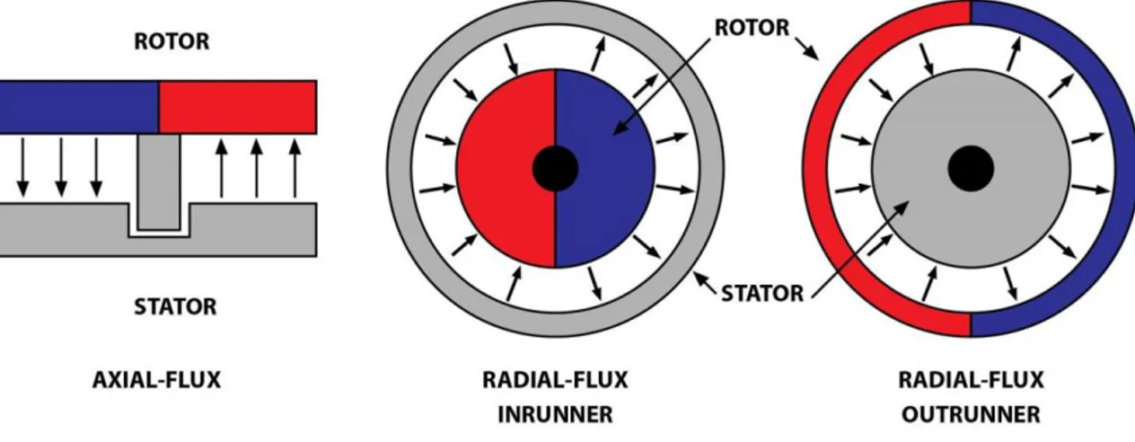
In Figure 3 is shown the two basic configurations of electric motors, they can be radial flux or axial flux motors. In the radial flux motors, there are two possible concepts in respect to the rotor: inrunner or outrunner.
Figure 3 - Motor configurations: radial flux inrunner rotor, radial flux outrunner rotor and axial flux disk rotor
7
2.1.2. Motor Losses and Efficiency
The losses in the motor are: • Stator core losses;
• Windings working current Joule losses.
The stator core losses are divided in magnetic hysteresis, that produces heat when changing the magnetization of the core, and induced currents (Eddy-currents) in the core, due to the core being normally conductive.
Normally, the most important share of losses in a typical brushless motor working at low driving currents is the core loss, due to Eddy-currents and magnetic hysteresis in the rotor core laminations. Normally, the core losses are minimized be the use of low hysteresis silicone steel in individually isolated layers forming a laminated structure perpendicular to the magnetic flux. One possible way of reducing core losses would be the use of the non-conductive ferrite like core materials such that these Eddy-currents would not occur but the production of such desired geometries in ferrite is not straightforward. Another way of getting rid of the core losses is to get rid of the core itself. One problem that arises from a coreless motor is that the magnets’ flux will run through the windings unchanneled by the lack of the core tooth. In this case, the Eddy-currents in the windings can be minimized by using parallel strands of individually insulated thin wires (Litz wire).
The stator windings produce losses whenever they carry current to produce torque. The winding losses or I2R losses are due to the current flowing through the conductors of the motor. These
losses are equal to the square of the current times the resistance of the path through which the current flows. At low speeds such as in an in-wheel motor, the I2R or the copper loss can
be higher than the core losses.
2.1.3. Back Electromotive Force and Torque Production
When the phases of a PMSM are energized and the current flows through them, torque is produced and makes the motor rotate. With the motor rotation, the rotor’s magnets change positions and the flux linkage changes, which induces a voltage on the phases according to Faraday’s law. This induced voltage is called Back Electromotive Force (BEMF) and it is, according to Lenz’s Law, opposite to the current that causes it. The magnitude of the BEMF is thus proportional to the frequency of the motor, so, if the motor is driven by a constant voltage, as the motor accelerates the magnitude of the phase current decreases. If the motor is running empty, it will stop its acceleration when the BEMF is equal to the supplied voltage, at this point, if no load is applied to the motor, the energy consumed is only due to mechanical losses.
8
The BEMF waveform is determined by the distribution of the flux in the air gap, that is dependent of the winding arrangement of the phases and the magnets positions. Figure 4 shows two BEMF waveforms a trapezoidal shaped BEMF is a characteristic of Brushless DC motors while the PMSM are characterized by having a sinusoidal BEMF.
Figure 4 – Sinusoidal and trapezoidal BEMF waveforms [3]
2.2.
Motor Controllers
The control strategy is a set of rules or algorithms that govern when and how the electronic power switches are turned on and off. The control strategy objective is to give smooth and accurate control of torque and speed, therefore the current level is limited in such a way that the motor efficiency is maximized. PMSM requires alternating phase currents that should be ideally replicate the motor’s BEMF. Typically, a sinewave. This allows for maximum efficiency, since current is supplied when it results in torque. If current is supplied to the coil when the magnet pole is aligned with it, i.e., when the phase BEMF is zero, the torque will be zero and all the supplied energy is wasted. In the case of a three-phase motor, each phase sine wave signal must be 120 electrical degrees out of phase relative to each other since this allows constant torque.
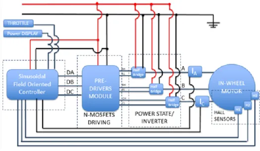
Typically, a PMSM controller can be divided in three modules (see Figure 5): motor electrical position sensing for correct phase commutation (equivalent to the brushes function in brushed motors; gate driving module and the gates themselves. In the first module, besides commutating to supply current in phase with the phase’s BEMF, the shape of the current
9 function should be modulated to replicate the BEMF itself. This is called the control strategy. Since the current function must be generated from a DC bus, a Pulse-Width Modulation (PWM) is normally used to control the current level (motor torque level control) and the current function shape in the respect to the motor electrical position. The second module only converts the digital logic electrical signal to a suitable gate operation power supply. The third module is responsible for connecting the phase terminal to the DC bus + or – terminal and disconnecting the phase when required. For this, electronic power switches are used: MOSFETs or IGBTs. MOSFETs are preferred when low DC bus voltages are used because they have a smaller resistance for the lower limit operation voltage. IGBTs have constant voltage drop which translate to lower relative power losses as the operating DC bus voltage increases.
Figure 5 - Typical Controller architecture
2.2.1. Three Phase Motor Commutation Scheme
2.2.1.1. Trapezoidal Commutation
PMSM are very similar to BLDC motors. The only difference being that the later type is supposed to have a trapezoidal BEMF. So, the commutation is necessary to generate AC from a DC bus. Nevertheless, the simplest way to commutate a PMSM motor from a DC bus is through the trapezoidal commutation. In this case a PMSM is working, in fact, as a BLDC motor. In this scheme, the current is controlled through motor terminals one pair at a time and having the third motor terminal disconnected (Figure 6). It uses six different stages, each separated by 60 electrical degrees. This control is based on the motor’s position. Normally, the motor position is obtained from three Hall Effect sensors. According, to the motor position the controller calculates the state in that the inverter must be such that the motor can produce torque. The Table 1 shows all the six states that can be observed.
10
Figure 6 – Current path on a trapezoidal commutation [4] Table 1 - Switching sequence for trapezoidal commutation
From the switching sequence results a current waveform that is trapezoidal. This commutation scheme is very simple and effective in controlling motor speed, but because this scheme only has six steps it tends to produce torque ripple depending on the actual motor BEMF.
2.2.1.2. Sinusoidal Commutation
By energizing all the three phases with sinusoidal currents (see Figure 7) it is possible to eliminate the plateaus shown in the trapezoidal commutation current waveform and replace them by waveforms that are sinusoidal. By having all the three phases energized continuously (see Table 2) a smoother torque is achieved and a more precise control can be reached. Usually, for minimal torque ripple and maximum efficiency the current waveform should match the BEMF waveform and be kept in phase with it.
Figure 7 – Current path on a sinusoidal commutation [4]
Interval (degrees) Hall A Hall B Hall C ON Switches Phase A Phase B Phase C
0 to 60 1 0 1 S1, S6 + 0 -60 to 120 1 0 0 S3, S6 0 + -120 to 180 1 1 0 S3, S2 - + 0 180 to 240 0 1 0 S5, S2 - 0 + 240 to 300 0 1 1 S5, S4 0 - + 300 to 360 0 0 1 S1, S4 + - 0
11
Table 2 - Switching sequence for sinusoidal commutation
The sinusoidal commutation requires high resolution position sensing, and the Hall effect sensors used in the trapezoidal commutation are usually replaced by an encoder. For this reason, the sinusoidal commutation is more expensive than the trapezoidal commutation but provides reduced torque ripple.
2.2.2. Phase Current Level Control
2.2.2.1. PWM Current Control
PWM finds application in many fields, from the command of servo position to the transmission of digital data by a single signal in a serial protocol. In motors, PWM is a way of controlling the current level by turning the circuit on and off in pulses of different duration. Consider a load where the power supply is on during half of the time, in this case, the mean current level would be half the full power level. So, the current level is proportional to the turned-on time fraction. When PWM is used in motors, the switching frequency is high enough such that the current ripple in the circuit is quite limited. The motor inductance limits the current gradient in time. So, what happens is that when the circuit is turned on: the current increases, when the circuit is turned off: the current decreases.
Typically, brushless motor controllers are based on PWM, relying on the inductance of the motor windings to smooth the current flow through the motor. If a purely resistive load has a PWM voltage waveform applied to it, the resulting current keeps the same waveform and is directly proportional to the instantaneous applied voltage, resulting in an unsmoothed pulsed current waveform – rippled current. The motor torque will be proportional to the mean current, but the motor Joule losses are proportional to the instantaneous current squared. Thus, the controllers depend on the inductance of a motor coils acting as filters for the resulting current, with a time constant of L/R. The rate of current variation in time is smaller in higher inductance circuit loads. since the current ripple degrades the motor efficiency, in a low inductance motor, higher switching frequencies are necessary to limit the current ripple to acceptable levels.
Interval (degrees) Hall A Hall B Hall C ON Switches Phase A Phase B Phase C
0 to 60 1 0 1 S1 , S6, S5 + - + 60 to 120 1 0 0 S1 , S6, S2 + - -120 to 180 1 1 0 S1 , S3, S2 + + -180 to 240 0 1 0 S4 , S3, S2 - + -240 to 300 0 1 1 S4 , S3, S5 - + + 300 to 360 0 0 1 S4 , S6, S5 - - +
12
Using high PWM switching frequencies, an almost perfect sinusoidal AC can be modulated. In Figure 8, an analog circuit is presented that allows the creation of PWM AC. In this circuit, a comparator is fed with a reference sinusoidal wave signal, Ursw, in the positive terminal that is compared with a triangular wave signal in the negative terminal, Utw. When 𝑈𝑟𝑠𝑤− 𝑈𝑡𝑤 > 0 => 𝑆𝐴= 1, such that a pulse to the gates driver is generated. During the width of the pulse, the upper left gate and lower right gate close the circuit, applying +𝑉𝐷𝐶 to the A phase motor terminal. During this condition, 𝐼𝐴 increases in time with an increase rate proportional to the motor inductance. When 𝑈𝑟𝑠𝑤− 𝑈𝑡𝑤< 0 => 𝑆𝐴= 0 , −𝑉𝐷𝐶 is applied to the A phase motor terminal, making 𝐼𝐴 decrease in time. Another possibility is a digital current controller based in sine function look up table for SA pulse width versus time determination.
13
2.2.2.2. Hysteretic Phase Current Control
By using a hysteretic controller is it possible to shape the current waveform to any shape desired. In this method, each phase current is compared to a reference wave and switched in accordance with that. The switching signals are generated due to the error in the current waveform by comparing the reference current and the actual current (see Figure 9). If the actual current is higher than the upper limit of the hysteresis band the upper switch of the inverter should be turned off and the lower switch turned on such that the current falls. If, by the other hand, the actual current reaches the lower limit of the hysteresis band the lower switch of the inverter is turned off and the upper switch is turned on and the current starts to rise coming back to the hysteresis band. The band width is directly proportional to the current ripple and inversely proportional to the switching frequency.
Figure 9 - Typical Hysteresis Current Controller [5]
2.2.2.3. Multilevel Inverter for Phase Current Control
A modern trend in inverters are the Multilevel topology inverters where n voltage levels are used to synthetize a sinusoidal voltage from a DC. Compared with the two-level inverter the multilevel inverter improves the output voltage quality, as shown in Figure 10 where is visible the improvement of the output voltage quality from a two-level inverter, in Figure 10 a), to a nine-level inverter on in Figure 10 c).
14
Figure 10 - Multilevel Inverter Output [6] a) two-level inverter, b) three-level inverter and c) nine-level inverter.
There are several topologies of multilevel inverters available and the differences are related to the switching mechanism and the source of the input voltage. Rodríguez et al [7] present a summary of multilevel inverter circuit topologies and their control strategies as well as their evolution.
Figure 11 – Multilevel inverter representation with: two levels a), three levels b), and n levels c)[7]
The circuit of level inverters is shown in Figure 12. The inverter in a) provides a three-level output across phase terminal A. In the basic circuit, a three-position switch selects the voltage level for the phase terminal A. Unfortunately, such three-position switch does not exist
15 in discrete electronic components. So, to actually implement such circuit, there are a few options: Figure 12 b) shows the diode clamped topology and c) is the flying capacitor version of circuit a). In the diode clamped version, A can be at +VDC if switches S1 and S2 are on. S1’
and S2’ are complementary to S1 and S2, respectively. So, they are off in such condition. A is at
zero voltage level if S2 and S1’ are on. A is at -VDC if S1’ and S2’ are on. In the Flying capacitor
topology, independent capacitors clamp the device voltage to one capacitor voltage level. In this case, S1’ and S2’ are not complimentary to S1 and S2. To set the A terminal voltage level at
+VDC, only switches S1 and S2 are on; if only switches S1’ and S2’ are on, A is at -VDC; to set A
at zero voltage, only S1 and S1’ are turned on, making the capacitor C1 charge while trying to
keep the 0 voltage or if C1 is charged, only S2 and S2’ are on to allow C1 to discharge while trying
to keep the zero-voltage level. So, the charge of C1 is managed by the selection of the S1, S1’
or S2, S2’ switch combination. If the neutral terminal, in a single-phase motor had a similar
three-level inverter, the three-level inverter would become a five-level inverter.
Figure 12 – Three-level inverter: a) basic circuit; b) implemented in a diode clamped topology; c) implemented in a flying capacitor topology adapted from [7]
The advantage of multi-level inverter becomes obvious when the load has low inductance and resistance, as in the case of a very efficient (low phase resistance) coreless (low inductance) motor. Specially, when the main factor opposing to the load current demand is the BEMF that changes with the motor speed, i.e., with the vehicle velocity. Figure 13 shows the circuit of a single-phase load, five-level inverter with the Cascaded Multilevel inverter topology. It is based on single-phase full-bridge inverters connected in series with two separate DC sources. The resulting voltage level at the terminal A is synthesized by the addition of the voltages generated by the different levels [7].
16
Figure 13 - Castaded half-bridge inverter [7]
2.2.2.4. Field Oriented Control
Field Oriented Control (FOC) is an advanced control technique to drive electric motors that controls the stator currents by a space vector formulation to synchronize the phase current level with the phase BEMF. By knowing the exact position of the rotor, the controller calculates the inverter state to ensure that the stator field will be exactly 90 electrical degrees behind the rotor field (see Figure 14).
Figure 14 - Field Oriented Control Implementation [8]
FOC sees the three-phase stator currents (see Figure 14) as a flux and a torque components and controls both quantities separately. Through the Clarke’s transformation the three-phase
17 sinusoidal currents (IA, IB, IC) are transformed into a two-phase time variant system (α, β) that
depends of the rotor frequency. Next, by using the Park’s transformation, it is possible transform α and β into a two-coordinate time invariant system (d, q) that is constant at a given rotor frequency. Where d-axis represents the flux, that is a function of the rotor position, and the q-axis represents the torque, that is a function of current. Depending of the input (desired torque), the control process redefines a new q quantity and adjust the d quantity in order to have d and q 90 degrees apart. Through the inverse Park transformation, the new quantities of α and β are calculated and translated back to the three-phase sinusoidal. Figure 15 shows a summary implementation of the FOC.
Figure 15 -Field Oriented Control Implementation [9]
2.3.
State of the Art
In these section the latest efforts regarding motors and controllers that relate directly to the current work are highlighted.
2.3.1. PMSM Electrical Machines
Considering the presented PMSM fundamentals, the design concept for our motor is the three-phase axial flux coreless machine. The current state of the art review is, thus focused in this configuration. The works that present the actual efficiency of the motors or equivalent generators were favored. In reality, as explained in Section 2.2 the actual efficiency of the PMSM that must run from a DC bus supply can only be adequately measured if the motor is working in the generator mode or if it is run with a perfect controller.
Caricchi et al [10] describe the design, construction and experimental testing of an electric propulsion system to use in a dual-power city car based in an in-wheel three-phase coreless PMSM. A water-cooled axial-flux twin configuration for direct drive was developed. The twin motor configuration allowed the use of series to parallel motor connections adapting the system to vehicle speed and torque requirements. The efficiency curve with rotation speed was
18
remarkably flat near a maximum of 97%. Contributing to this performance was the controller that was part of the same development effort.
A solar vehicle in-wheel three-phase coreless PMSM was developed by CSIRO [11]. The motor uses an axial flux pancake configuration (see Figure 16). A Hallback magnet array was used to maximize the motor torque constant. Litz wire was used to minimize the induced current losses in the copper. The parametric study concerning the design is presented together with the design point performance. The final design weights 6 kg with 4.8 kg of rare earth Neodymium magnets, reaching an estimated efficiency is 97.8 %, the motor power is 1800W at 1060 rpm. This motor has been made commercially available as a kit by Marant [12] for around 10000 euros. A variant with a simple magnet array is also available at a lower cost but lower peak efficiency. These two versions are being used by various solar vehicle teams all over the world. Due to the low time constant, the high-end controller Titrium is used but still with 100 µH inductors in series with the motor phases. The CSIRO motor is too powerful for a SEM prototype vehicle.
Figure 16 - Motor CSIRO [12]
Wang et al [13] described a method to calculate the performance of a coreless stator axial flux permanent-magnet (AFPM) generator. By combining the finite-element analysis and a theoretical analysis a multidimensional optimization methodology was created to optimize the design of AFPM generator. The results shown that the performance of the manufactured prototype is consistent with the predicted results.
Colton [1] presents in its MsC thesis, simple, low-cost design and prototyping methods for custom brushless permanent magnet synchronous motors. Different modulation strategies are explored to design the motors prototypes. He shows that using a first-order motor model analysis can predict the motor’s performance with good accuracy. Three case-study motors
19 were used to develop, illustrate and validate the rapid prototyping methods for brushless motors, proving that these are useful in the fabrication of case study motors. One of the three case study developed motors was an axial flux coreless PMSM that showed a disappointing efficiency. This was attributed to not having considered the induced current losses in the copper of this coreless motor. Therefore, not having used Litz wire for that motor.
LaunchPoint Technologies, Inc in September of 2009 [14] presented a high efficiency brushless motor. Figure 17 shows the LaunchPoint’s Electric Motor, it is axial flux with a dual permanent magnet Halbach array, also have an ironless rotor and stator to eliminate the eddy currents and hysteresis losses and an efficiency of 95%. This motor has the higher power density on the market, with 7 horsepower at 8400 rpm and 0,65 Kg of weight, it produces 11 horsepower per kilogram.
Figure 17 - LaunchPoint’s Electric Motor [14]
Students from the Norwegian University of Science and Technology have been working on Axial Flux PMSM for their participations in Shell Eco-marathon. Their work was based on Lubna Nasrin design and the fabrication of the motor was described by Dahl-Jacobsen but the real performance of the motor wasn’t the expected, so in 2012, Endresen [15] reports another build version of the Lubna Nasrin motor [16] where with changes in the motor windings and with a new arrangement of the magnets from a conventional North-South to a Halbach array, they believed that the motor would achieve 97,2% efficiency, with a mass of 6,24 kg. However, this improved version was measured reaching an efficiency of only 68%. This disappointing value was attributed to the difficulties found in the production of the rotor and the wiring. In 2013,
20
Buøy [17] built another version of the motor based in the Nasrin design but using different production methods.
Batzel et al [18] starting from requirements and drive constraints, such as power, speed, voltage and diameter designed and test an ironless axial-flux PMSM. A Halbach array was used to concentrate the magnetic flux on the air gap and allowing the absence of the backiron and reducing the weight of the motor. The machine efficiency was determined by measuring de phase voltages and currents – input and measuring the torque and speed of the shaft – output. The total weight of the motor was 4.8 kg and an efficiency over 90% was reached across the range of his operation.
Piggott developed a successful coreless permanent magnet, PM, generator for small-scale wind turbines. His design found widespread use since his designs and build instructions are published on various e-books and the vast majority are free to download. Beside the e-books, Piggott gives workshops around the world training the average person to build his generators. One of his first designs from 1993 was a PMG made by using a brakedrum from a Ford Transit. He built a three-phase radial-flux with ten coils per phase with a laminated core from an old electric motor [19]. In 2001 a new generator was published and it consists in machine that is a three-phase axial-flux with pancake configuration and four pole pairs mounted on each rotor disk and two concentrated coils per phase that are embedded in a polyester resin stator reinforced with fiberglass mat [20]. The rotor disks are made from car breaking disks and the magnets are regular grade 3 ferrite magnet blocks. In 2003 a new design plans were launched and some modifications to the configuration were made it became a 12 pole pairs 10 coils with five-phases [21]. The efficiency is not reported, but it is considered significantly better than the commercial ones.
Bumby et al described the design, construction and testing of two PMG for use in small scale wind turbines, one with 1kW of rated power and the other with 2,5kW, both generators were three-phase and had a pancake configuration with eight pole pairs and 4 coils per phase. They end up with a generator that is 93-94% efficient. They only had a maximum difference of 5% between the predicted and measured performance [22].
2.3.2. Motor Controller
The development of motor controllers and inverters has been extensive in later years. This is due to the expansion of grid tied solar roofs in the case of inverters and due to the advent of electric plug-in cars. Motor controllers and inverters are very similar. Only the works that inspired the adopted controller solution are referend herein.
Due to the very low inductance that coreless PMSM are characterized, Caricchi et al [10] implemented a current ripple reduction by adjusting the voltage supplied to the motor
21 controller in accordance with the motor’s EMF using a dc-to-dc buck-boost converter. Figure 18 represents the layout of the motor drive control system presented.
Figure 18 - Layout of the motor drive control system presented by Caricchi et al [10]
Colton [1] also, in his MsC thesis developed, built and tested a brushless motor controller with two channels and 1kW per channel. Great efforts were made to implement FOC on low-cost hardware. The electrical requirements for the controller and selection of the main components also were discussed in his report.
Bossche et al [23] developed a three-phase BLDC motor controller to fit in a small Electrical Vehicle. This controller is based in a Programmable Logic Device, they realize that for their controller only use combinatory task, such as AND, OR, Enable and with some additional analog and digital electronics they don’t need a complex microcontroller. They implemented a very simple torque control where the current supplied to de motor is measured in two phases and the third is analogical calculated.
23
Chapter 3
3. Methodology
In the present chapter reports the development of both: motor and controller.
3.1.
Motor Development
This first section describes the efforts to develop the SEM car prototype motor. The implemented concepts in the motor are described in the conceptual design (Section 3.1.1), then a preliminary design was computed embodying all the concepts. Finally, a detailed design was created in CATIA 3DCAD software supported by performance calculations in the form of parametric studies. Finally, a prototype was built and tested.
3.1.1. Conceptual Design
To design and build a motor, important decisions must be made in the conceptual design phase having in consideration: the different types of motors, the availability of different materials, the access to fabrication machinery and the total cost of the motor. It is very important to match the motor typology to its function and to respect the current objective of obtaining an ultra-efficient motor.
In electric vehicle applications, the use of a direct-drive motor is desirable because of the elimination of the reduction and transmission losses. At the same time, results in low vehicle cost and system volume, higher reliability and an increase of the total vehicle efficiency. In consideration of the high-torque operation required at relatively low speeds, permanent magnet (PM) motors are best fit to the direct-drive application [24]. So, from the beginning of this project one choice was made, an in-wheel direct drive motor will be used. In this motor, electronic commutation can be used in lieu of mechanical brushes, although the electronic commutation complexity, the efficiency and reliability favors this type of motor in our application. It was decided to develop the motor from the concept previously used with success in solar electric car competitions, the CSIRO motor [11]. It is an axial flux permanent magnet coreless synchronous motor. One important requirement is, thus, that the motor should fit inside the wheel, reducing the aerodynamic drag and maximizing the efficiency. Such type of motor has low inductance, L, because it has no iron core in its coils, and at the same time, it must have the lowest possible resistance, R, because the Joule losses are directly proportional to the resistance. It is, thus, characterized by very high phase current gradients while despite the efforts to reach a low R, the time constant L/R will remain extremely low. Therefore, this type of motor it is prone to very large current ripple. This is the reason why it was decided that
24
the motor and controller should be developed in a single work package. The efficiency of the motor running in the vehicle depends from the controller performance.
In the conception of the Aero@UBI01 car, in the initial stage, a model to predict the car performance was developed with the most significant parameters regarding to the car performance, with this model the motor power requirements were determined.
SEM race rules dictate that the prototype category vehicles must perform with a mean speed of 25 km/h for the race (7.03m/s). In our case, it was realized that, in the same way the electric current ripple increases the Joule energy losses in the motor for the same mean current value, an airspeed ripple during the race increases the drag losses for the same mean value of 25 km/h. So, considering the absence of atmospheric wind during the race and that the race track in Rotterdam, Netherland, is mostly flat, it was decided that the driver must maintain the 25 km/h and, thus, the motor is designed for maximum efficiency at that continuous power and torque design point condition with the possibility of having moments during the race where higher power or torque is needed. E.g., overtaking another vehicle in the racing circuit. Considering the wheel diameter of 0.478m, the angular speed of the motor will be 29.4 rad/s. Regarding the motor efficiency goal, the parametric study of the car prototype performance indicated that the motor could be made 3kg heavier if the efficiency would rise 1%.
Table 3 - Motor requirements
The conceptual design of the motor results from the implementation of multiple ideas and concepts. Here is a list of the other implemented concepts:
• PMSM – is the motor type that achieves the highest efficiency as explained in Chapter 2. So, the intent was to pursuit a PMSM machine driven by a close to sinusoidal current; • In-wheel direct drive- for the nonexistent transmission losses and motor bearings losses and no volume is required inside the vehicle for transmission and the motor itself; • Axial flux rotor configuration - is suitable to fit in the vehicle’s wheel (see Figure 22); • Coreless – the iron laminate core of most PMSM is responsible for Eddy current losses and magnetization hysteresis losses. One drawback of the coreless motor concept is that Eddy current losses occur in the stator copper windings but can be prevented by
Requirement
Value
Continuous output shaft power (cruise)
15W
Peak shaft power (climb)
400W
Rotational speed at 25.1km/h (7,03m/s)
29.4 rad/s
Continuous Torque (cruise)
0.510Nm
Peak torque (climb)
13.605Nm
Maximum Outside diameter
370mm
25 the use of suitable Litz wire [11]. Another drawback is that the magnet flux is not forced into the coil dispersing at a short distance from the magnets faces. So, thin stator coils that are very close to the magnet face are required;
• Steel back rotors – the magnetic flux between rotor magnets is closed by ferromagnetic steel plates that act also as a structural rotor support to hold the magnets;
• Litz wire use – to minimize Eddy current losses occurring in the stator copper, the use of Litz wire was mandatory. The copper wire Eddy current losses are proportional to the fourth power of the wire diameter [13]. From the search for a Litz cable provider, the commercially available specifications and the stator geometry and dimensions led to the choice of the 10x18 individually insulated wires of 0.1mm diameter;
• Configurable motor – the use of a single wave winding turn from a cable of 10 sets of 18 individually insulated wires allows to configure the motor winding with multiple winding options. From the basic configuration of a single turn with 180 parallel wires to a 10 turn coil of 18 parallel wires. In this manner, the motor constant is, in fact, adjustable to a different application of the motor;
• Three-phase – because it is the minimum phase number allowing constant torque which is crucial when starting the vehicle;
• Minimized stator thickness between opposing magnet poles faces – due to the coreless concept magnet flux dispersion, the thinner the stator the better. This was achieved by adopting wave winding and using a single turn per phase for the motor. So, the motor stator is as thin as a single squeezed cable of 10x18 isolated wires (~3mm). The three phases do not overlap in the stator between the magnets, they overlap in the radial inner and outer edges of the stator, outside the inter faces region existing between opposing magnets;
• Wave winding – wave winding was adopted because allows the smaller stator thickness (see Figure 19);
• Special end-turns inter-phases overlapping – the overlapping of the phases windings is limited to radial inner and outer edges of the stator, contrary to the CSIRO in-wheel motor where they overlap in between the opposing magnets faces [11];
• N52 NdFeB magnets - rare earth magnets are becoming standard in PM motors. They allow greater magnetic flux in the stator coils per magnet unit mass. Thus, reducing the coils turns therefore the length of coil wire, therefore smaller phase resistance, size and weight to reach a given motor constant, Kt, and efficiency. The drawback of
these higher specification limit magnets is the operating temperature limit (80ºC). But, for a high efficiency and small power motor with little restrictions in size and weight, the temperature builds up in the motor is not an issue;
• Low cost magnets per unit mass - the mass of magnets relates inversely with the size of required coils to reach a given motor constant, Kt, and efficiency. So, to make use
of the least cost restricted mass of magnets possible, the commercially available NdFeB magnets with lowest price per unit mass were identified. For the small number of
26
magnets necessary for the motor prototype, the minimum price that was found was 51€/kg. Given all the geometrical constrains and number of pole pairs optimization, the chosen magnets were at a price tag of 60€/kg;
• Gap between magnets – the placement of magnets was such that there was a gap between them approximately equal to the magnet thickness because it was believed that such arrangement would result in a BEMF closer to sinusoidal.
• Adjustable air gap – although the air gap is, generally, minimized, the option to make it adjustable allows to fine tune the motor constant to the actual motor use.
The final conceptual design of the developed motor is shown in Figure 20, Figure 21 and Figure 22.
Figure 19 - Wave winding concept
27
Figure 21 - Motor section concept
28
3.1.2. Preliminary Design
The motor design variables were: Voltage of the DC bus, 𝑈𝐷𝐶; Shaft Power, Pc; angular speed, 𝜔; Motor Efficiency, 𝜂𝑐; mean radius at magnets center position, r; magnet poles number, p; flux intensity of the magnets, 𝐵𝑚𝑎𝑔; magnet thickness tm, Stator filling factor, FF; magnet pole length, L; magnet pole width, W and the airgap thickness of 2mm. So, in the first design iteration, all these variables values were assigned.
In the case of 𝑈𝐷𝐶, it had to be a multiple of 3.7V because the SEM competition rules mandate the use of a lithium-ion battery. In the first design iteration, the value was set to 7.4V but the final design point uses 15V and the actual vehicle’s battery uses 22.2V to reach a top speed sufficiently above the design speed. Table 3 shows the values that were used for Pc, 15W, for 𝜔, 29.4rad/s and the maximum radius of the motor, 340mm/2=0.17m.
The main constrain for the motor development was the motor cost and he main cost share was found to be for the magnets. So, these were chosen for their low cost; their geometric suitability to the in-wheel motor, and peak magnetic flux density rating. The adopted magnets were N52 flux rated NdFeB magnets with L=0.030m; W=0.012 and tm=0.012 m costing 60€/kg. So, the mean radius of the magnets was set at 0.15m (0.17-0.03/2=0.155 subtracted of a 5mm radial margin). The magnetic flux density of these N52 specified magnets reaches a 𝐵𝑚𝑎𝑔=1.48T. A stator filling factor of FF =0.3 was assumed. The major unknowns were the number of magnet poles and the efficiency that the motor could be designed for. So, during the design iterations, p was varied in the range of 32 to 40 and 𝜂𝑐 from 0.96 to 0.99.
To model the motor, the first step is to obtain the available AC tension, 𝑈𝐴𝐵𝑟𝑚𝑠 from the U (1).
𝑈𝐴𝐵𝑟𝑚𝑠 =
√3
2√2𝑈 (1)
The motor electrical power is obtained from the shaft power, using the design point motor efficiency (2).
𝑃𝑒= 𝑃𝑐 𝜂𝑐
(2)
From the motor electrical power, the motor current is obtained (3).
𝐼𝑟𝑚𝑠= 𝑃𝑒
29 The motor phase current is also obtained from the motor electrical power, (4).
𝐼𝐴𝐵𝐶 𝑟𝑚𝑠= 1 √3 𝑃𝑐𝑒 𝑈𝐴𝐵𝑟𝑚𝑠 (4)
Knowing motor phase current, the motor total Joule power loss is calculated with Equation (5) assuming half the losses will occur due to internal flow drag (windage loss) and eddy-currents in the copper. So, the windage power loss is equal to the Joule power loss.
3𝑅𝐼2= (𝑃𝑐𝑒− 𝑃𝑐)
2 (5)
The phase winding resistance is found from the total Joule power loss by Equation (6).
𝑅 = 𝑅𝐼 2
3𝐼𝐴𝐵𝐶𝑟𝑚𝑠
(6)
The motor resistance voltage drop, which is the required electromotive force to reach the motor phase current is calculated from Equation (7).
𝑈𝑒𝑚𝑓= 3𝑅𝐼𝐴𝐵𝐶𝑟𝑚𝑠 (7)
The required motor effective back electromotive force, 𝑈𝑏𝑒𝑚𝑓𝑟𝑚𝑠, is obtained from Equation
(8).
𝑈𝑏𝑒𝑚𝑓𝑟𝑚𝑠 = 𝑈 − 𝑈𝑒𝑚𝑓 (8)
The motor constant 𝐾𝑡 is now obtained from Equation (9).
𝐾𝑡=
𝑈𝑏𝑒𝑚𝑓𝑟𝑚𝑠
𝜔 (9)
The angle corresponding to half electric revolution is calculated from the motor pole pair number p from Equation (10).
𝛼 =2𝜋
30
The duration of the coil motion from one magnet to the next is calculated from Equation (11).
𝑡𝑚𝑎𝑔 = 𝛼
𝜔 (11)
The motor stator mean perimeter is given by Equation (12).
𝑝𝑒𝑟= 2𝜋𝑟 (12)
The stator outer perimeter is given by Equation (13).
𝑝𝑒𝑟𝑜𝑢𝑡= 2𝜋𝑟 [𝑟 + 𝐿
2+ 0.005] (13)
The stator inner perimeter is given by Equation (14).
𝑝𝑒𝑟𝑖𝑛𝑛= 2𝜋𝑟 [𝑟 −
𝐿
2− 0.005] (14)
The distance between opposing magnets faces, for the air gap in each face of the stator plus the stator itself with thickness, 𝑡𝑠, (see Figure 20) is determined by Equation (15).
𝑔 = 𝑡𝑠+ 4 (15)
Regarding the mean flux density at the stator, it was considered to be 90% of the peak magnet flux density and proportional to the total thickness of the magnets surrounding the stator coil, 2t (see Figure 20) is determined by Equation (16).
𝐵𝑐𝑜𝑖𝑙= 0.9𝐵𝑚𝑎𝑔 2𝑡
(𝑔 + 2𝑡) (16)
The wave winding coil area subjected to the magnetic flux is calculated according to Equation (17).
𝐴 = 𝐿𝑊𝑝 (17)
31
ϕ = 𝐴𝐵 (18)
The pole width available at the mean stator perimeter is 𝑝𝑒𝑟/2. The desired magnet width was checked as 𝑝𝑒𝑟/4. It should be close to W such that the gap between successive rotor magnets was close to the value of W. It could never approach 2W or the magnets could not be fitted in the rotor.
The flux gradient in the stator coil is considered as 2ϕ
𝑡𝑚𝑎𝑔. A maximum single coil voltage drop was calculated by Equation (19).
RI = 1.25𝑅𝐼𝐴𝐵𝐶 𝑟𝑚𝑠 (19)
So, the required maximum phase voltage is given by Equation (20).
UABC= UABrms
√3 − 𝑅𝐼 (20)
The required turns per coil is obtained from Equation (21). The actual design point had to correspond to a finite N number.
𝑁 =UABC 2ϕ 𝑡𝑚𝑎𝑔
(21)
The length of coil wire per turn per coil is obtained from Equation (22).
𝑙𝑝 = 2𝑝(𝐿 + 0.01) + 0.6𝑝𝑒𝑟𝑜𝑢𝑡+ 0.6𝑝𝑒𝑟𝑖𝑛𝑛 (22)
The total wire length per coil is obtained from Equation (23).
𝑙𝑁= 𝑁(𝑙𝑝+ 1) (23)
The minimum copper coil wire section area was calculated from Equation (24) considering a copper wire resistivity at 40ºC of 2.06x10⁻⁸Ωm.
𝐴𝑁= 2.06128×10⁻⁸ 𝑙𝑁
32
The corresponding diameter was calculated from Equation (25).
𝑑𝑤𝑖𝑟𝑒 = 2√ 𝐴𝑁
𝜋 (25)
The minimum copper volume per phase was calculated from Equation (26).
𝑉𝑤𝑖𝑟𝑒= 𝐴𝑁𝑙𝑁 (26)
The motor stator copper mass for the required copper volume per phase was calculated by Equation (27) considering a copper density of 8930kg/m3.
𝑚𝑤𝑖𝑟𝑒= 8930𝑉𝑤𝑖𝑟𝑒 (27)
The stator disk area perpendicular to the axial axis was calculated from Equation (28).
𝐴𝑆= 2𝜋 [(𝑟 + 𝐿 2+ 0,005) 2 − (𝑟 −𝐿 2+ 0,005) 2 ] (28)
The required stator thickness was calculated considering the filling factor from Equation (29).
𝑡𝑠= 3𝑉𝑤𝑖𝑟𝑒
𝐴𝑆𝐹𝐹
(29)
The required motor magnets mass was calculated, considering the filling factor from Equation (30) and considering a NdFeB magnet density of 7500kg/m3.
𝑚𝑚𝑎𝑔= 2𝑝(7500𝑊𝐿𝑡𝑚) (30)
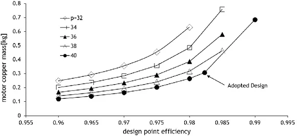
In order to decide what pole count, p, would be used in the motor, a parametric study was performed to see how much mass would the motor have due to the desired design efficiency. So, calculations where performed to determine the copper mass in the stator windings due to the adoption of different pole count in function of the design point efficiency of the motor. The study was performed in a range of 32 to 40 poles. The magnet mass for 32 poles was
33 estimated at 2.1 kg and for 40 poles a value of 2.6 kg was expected. The results are presented in Figure 23. The results for the total mass of rotor magnets plus stator copper are presented in Figure 24. The adopted design was considered a good compromise between magnet mass, the corresponding cost and the value of efficiency that corresponded. A higher magnet poles number would increase even further the total magnet mass and, thus, motor cost.
Figure 23 - Motor stator copper mass due to pole count in function of design point efficiency
34
3.1.3. Detailed Design
From the preliminary design study presented in Section 3.1.2 and implemeting the concepts from the conceptual design (Section 3.1.1) the final design of motor was created in CATIA V5 CAD software. Table 4 shows the parameters of the adopteddesign.
Table 4 – Motor Parameters
The motor design is based in the two principal parts of the motor: the rotors and the stator. The rotors plates are separated by 20 screws that resist to the magnentic attraction between the rotors magnets, this screws are also used to align the rotors in the assembly and dissasembly of the motor and to ajust the air gap. The stator is secured in position by three screws that allow adjustment of its plane in relation to the rotors in order to correct any misalignment if necessary. A CAD rendering of the motor in an exploded view is shown on Figure 25.
35
Figure 25 - Final motor design
3.1.4. Fabrication
Through the simplification of the motor design it was possible to fabricate most part of the motor’s components in-house. The rotor back steel plate was only component that had to be manufactured outside.
3.1.4.1. Stator
The stator of the motor is composed by an I profile shape (shown in Figure 21) in a circular solid revolution containing the three-phase windings. Figure 26 shows how the three-phase windings are distributed in space respecting the configuration shown in Figure 19.
36
To make the desired stator shape, the selected manufacture process was resin casting. From the detailed design, a female mold with two parts corresponding to both faces of the stator was made from high density polyurethane foam (Sikablock®) using a three-axis Computer
Numeric Control (CNC) router. In the fabricated mold, the position of the three-phase windings were marked (see Figure 27) and then the copper Litz wire was placed according to each phase winding position. Figure 28 shows the placing of the windings in the female mold before casting resin. The mold was then closed and filled with epoxy resin.
Figure 27 - Phase winding markings
![Figure 4 – Sinusoidal and trapezoidal BEMF waveforms [3]](https://thumb-eu.123doks.com/thumbv2/123dok_br/18179342.874354/30.892.159.659.235.647/figure-sinusoidal-trapezoidal-bemf-waveforms.webp)
![Figure 9 - Typical Hysteresis Current Controller [5]](https://thumb-eu.123doks.com/thumbv2/123dok_br/18179342.874354/35.892.159.792.471.735/figure-typical-hysteresis-current-controller.webp)
![Figure 10 - Multilevel Inverter Output [6] a) two-level inverter, b) three-level inverter and c) nine- nine-level inverter](https://thumb-eu.123doks.com/thumbv2/123dok_br/18179342.874354/36.892.206.646.107.557/figure-multilevel-inverter-output-level-inverter-inverter-inverter.webp)
![Figure 12 – Three-level inverter: a) basic circuit; b) implemented in a diode clamped topology; c) implemented in a flying capacitor topology adapted from [7]](https://thumb-eu.123doks.com/thumbv2/123dok_br/18179342.874354/37.892.204.736.470.714/figure-inverter-circuit-implemented-topology-implemented-capacitor-topology.webp)
![Figure 16 - Motor CSIRO [12]](https://thumb-eu.123doks.com/thumbv2/123dok_br/18179342.874354/40.892.122.728.486.816/figure-motor-csiro.webp)
![Figure 18 - Layout of the motor drive control system presented by Caricchi et al [10]](https://thumb-eu.123doks.com/thumbv2/123dok_br/18179342.874354/43.892.168.769.190.397/figure-layout-motor-drive-control-presented-caricchi-et.webp)