Evaluation of mechanical damage in concrete subjected to
uniaxial compression and tensile by diametrical compression
with longitudinal and transverse ultrasonic waves
Avaliação do dano mecânico em concreto submetido à
compressão uniaxial e à tração por compressão diametral
com ondas ultrassônicas longitudinais e transversais
a Pernambuco Catholic University, Post-graduate Program in Civil Engineering, Recife, PE, Brazil; b University of Colorado Denver, Dept. of Civil Engineering, USA.
Received: 26 Jul 2017 • Accepted: 21 Dec 2017 • Available Online:
A. V. P. ARAUJO a
F. A. N. SILVA a
C. L. NOGUEIRA b
J. A. SILVA a
Abstract
Resumo
In the research program both longitudinal and transverse ultrasonic waves were applied to concrete specimens under uniaxial compression and
tensile diametrical compression. A total of 45 concrete specimens with five (5) different mixes were loaded until failure. While load was being
applied – in compression and split tension – ultrasonic pulses were recorded and velocities calculated for both shear and pressure waves. The
results indicate that longitudinal or transverse ultrasonic waves can be applied in the evaluation of diffuse damage (microcracking in uniaxial compression) or concentrated damage (tensile microcracking by diametrical compression) imposed on the concrete mechanically through the
application of loads.
Keywords: concrete, ultrasonic testing, transverse and longitudinal wave velocities, uniaxial compression, split tension.
O trabalho discute o padrão de comportamento de ondas ultrassônicas longitudinais (compression waves) e transversais (shear waves) em concretos de variadas resistências submetidos a compressão axial e diametral. Foram ensaiados 45 corpos de prova confeccionados de concretos com variadas resistências a compressão. Os corpos de provas foram submetidos ao ensaio de compressão simples e tração por compressão diametral em máquina servo-controlada e, durante os ensaios, foram realizadas leituras de ondas de ultrassom longitudinais e transversais. Os resultados obtidos mostram que há alterações na velocidade de propagação de ondas, longitudinais e transversais, com o incremento do nível de tensão que é aplicado ao corpo de prova. Adicionalmente, foi possível observar que esta alteração de velocidade ultrassônica ocorre para nível de tensão próximo à tensão de ruptura. Os resultados obtidos indicam que ondas ultrassônicas longitudinais ou
transversais podem ser aplicadas na avaliação do dano difuso (microfissuração na compressão uniaxial) ou dano concentrado (microfissura -ção de tra-ção na compressão diametral) imposto ao concreto mecanicamente, através da aplica-ção de cargas.
1. Introduction
The need to investigate the structural behavior of concrete of differ
-ent strengths, growing risk of the environm-ent’s aggressiveness,
aging of structures, understanding behavior of structures
through-out their working life, requirements and performance criteria of
structures, all contribute to the growing demand for easy-to-apply rapid and reliable test procedures, which are able to provide quali-tative and quantiquali-tative information on the performance of concrete in conditions of use.
Many innovative research studies have been undertaken at a na -tional and interna-tional level to characterize the materials, evalu-ating qualitatively structural concrete properties using ultrasonic testing [1].
Researchers have looked to correlate the strength and deforma -tion properties of the concrete by non-destructive testing (NDT) in order to analyze the material in real situations of use, but various
factors influence this correlation, such as, for example, water-ce
-ment ratio, type of aggregate and thickening.
The cracking and degradation process of the elastic properties of concrete subjected to unconfined compression tests by emitting
longitudinal and transverse ultrasonic pulses has led to a drop in amplitude with a heavier load level which the concrete element
undergoes [2]. This finding could be a valuable tool for evaluating
the degree of damage to the investigated element. An important observation of the study was that there was some increase in mea-sured amplitude to low compressive stress levels for longitudinal waves. In the case of transverse waves, a steady drop in this
am-plitude was found for all stress levels studied. When evaluating the
change in ultrasonic pulse velocity as a measure of the damage to
structural concretes subjected to unconfined compression, a sud -den drop in the pulse velocity was noted from an 85% stress level of the tensile strength. In another study, the authors used the
tech-nique to successfully estimate the opening of cracks at different
levels of stress [3]. Moreover, the ultrasonic test can also be used
to evaluate the profile of thermal damage to concrete structures
exposed to high temperatures [4][5].
This study addresses the method of ultrasonic wave propagation used to understand the propagation pattern of longitudinal and
transverse waves in concrete of different compression strengths, undergoing unconfined compression and diametrical compression tests. The completed study gains in knowledge about specimen
testing, inasmuch as transverse waves (shear waves) were used instead of only longitudinal waves (compression waves), as nor-mally occurs in ultrasonic wave tests on concrete. Furthermore, the research also considered the fact that the concrete was
load-ed, under unconfined compression and diametrical compression,
when exposed to ultrasonic waves, thus allowing the capture of the
ultrasonic wave propagation profile with the stress level applied to
the specimen, both for longitudinal and transverse waves.
1.1 Importance of the research
There is an ever increasing urgent need to obtain information
about the behavior of structures throughout their working life, and
especially to meet recent requirements in the NBR 15575 perfor-mance regulations published in Brazil in 2013, and by the middle
of that year their use has already become mandatory, with stricter requirements especially for reinforce concrete structures [6]. The ultrasonic wave testing proves to be a valuable ally of builders and designers of reinforced concrete buildings, since it helps to obtain qualitative information about the structures in conditions of use without the need for destructive interventions [7].
The use of the longitudinal and transverse ultrasonic wave propa-gation to access qualitative information of concrete with varying compressive strengths is perfectly consistent with the current
Bra-zilian standards for design and execution of today’s concrete struc -tures that, in 2014, incorporated a possible design with concretes stronger than 50 MPa, a situation that was not considered in earlier versions of Brazilian standards. Today construction projects with concretes of high compressive strength can be designed and
im-plemented, which certainly behave differently from concretes with
moderate strength [8], [9].
In order to assess the efficiency of the ultrasonic pulse methods in detecting a process of internal cracking in concrete elements, stud -ies evaluate the velocit-ies and amplitudes of the ultrasonic signal
perpendicular and parallel to the cracking plane. The results indi -cated that both the velocity and amplitude of the signal provided
valuable data on the extent of the cracking process, even though
velocity has proven to be a more sensitive parameter [10]. The velocity of the ultrasonic pulse depends on the stress level in the concrete up to 70% for tensile strength [1].
In an analysis of the conditions of the conservation state of the concrete in the columns in a Rio Grande do Sul case study, an in-vestigation was carried out on a group of columns in use, in which there was a suspected drop in compressive strength in the test
batch of the tested concrete specimen. The investigation’s solution
to the problem was to use the ultrasonic pulse velocity test (UPV),
in which it was possible to verify the efficiency of this test in solv -ing this problem. The UPV test can be considered one of the most promising tests for evaluating concrete structures [5]. The study shows that UPV tests are sensitive to variations in homogeneity
and density, thus providing important data for making decisions
about conditions of concrete structures. UPV testing could also contribute to the quality control of the concrete structures in condi-tions of use [11].
2. Materials and experimental program
A total of 45 cylindrical specimens (D = 10 cm and h = 20 cm) were
prepared and subjected to increasing levels of unconfined com -pression and tensile diametrical com-pression until failure while, at the same time, longitudinal and transverse pulses with single-crys-tal transducers were transmitted and captured. Five (5) concrete mixes were prepared, nine samples for each mix (three samples to obtain the reference compressive strength, three samples for the ultrasonic pulse velocity test with axial compression, and three samples for the ultrasonic pulse velocity test with tensile diametri-cal compression).
The cement used in the experimental program was Portland
Ce-ment Clinker PC II F 31, with filler. This ceCe-ment has a compres
-sive strength class of 32 MPa, consisting of 90%-94% clinker and 10%-6% lime filler, pursuant to standard ABNT NBR 11578:1991.
is inert, with no chemical reaction, in order to minimize interfer-ences in the longitudinal and transverse wave propagation velocity inside the prepared test samples. Large and small aggregates of 19 mm crushed stone and course sand, respectively, were used. The materials were characterized in a technological laboratory for civil construction materials.
When making the concrete mixes in the study, three types of ad -mixture were used (Table 1), a plasticizer, superplasticiser and set-ting retardant. The plasticizer admixture and superplasticiser were
used in the mixes in which it was harder to obtain suitable work -ability, due to the high dry material content. The setting retardant was used in the mixes in which, with the use of the
superplasti-ciser, they would start setting very quickly, hindering the molding of
the specimens. Table 2 summarizes the compositions of the mixes used in preparing the concrete (mixes A, B, C, E and F).
After unmolding, the samples were wet-cured for 28 days. Before
undertaking the destructive and non-destructive tests, the speci -mens underwent grinding at the top and bottom. Lateral cuts to the specimen were made so that the transducers could be attached during ultrasonic testing (Figure 1). After grinding a new area ap-proximately 73.34 cm² in size was obtained for the specimens, so that the distance between the parallel surfaces created by the grinding is 9.66 cm. All tests were performed in the construction materials technological testing laboratory (Letmacc) at the Agua Fria Senai Technical School, Recife, Pernambuco, Brazil.
2.1 Ultrasonic pulse velocity test (UPV)
The Pundit ultrasonic instrument was used for UPV testing. Longi-tudinal and transverse transducers, both with a 500 KHz frequen-cy, were used and all transducers are produced by Panametrics. Every specimen underwent unloaded UPV testing. The transduc-ers were positioned so that the waves were read from direct
trans-mission, which is the most efficient way to transmit the ultrasonic
wave in continuous media [12].
2.2.1 UPV test with unconfined compression loading
This test required the following items of equipment: notebook, UPV
equipment, longitudinal and transverse transducers with a fre-quency of 500 KHz; servo-hydraulic universal press and concrete
testing microprocessor with maximum capacity of 2,000 kN; cou -plings suitable for the type of ultrasonic wave; PVC mold to attach the transducers (Figure 2) and a switching element.
The longitudinal and transverse transducers were attached to the
Table 1
Technical data of admixtures used in the study
Description Reference values
Sikament PF 175 MasterGlenium 304 MasterSet R 283
Chemical base Sulfonate salts & carbohydrates in water medium
Synthetic polymers & special admixtures
Sulfonate salts & special admixtures Aspect Brown liquid White & yellowish liquid Light brown liquid
Density 1.19 ± 0.02 kg/ liter 1.06 – 1.10 1.085 – 1.125
pH 5.5 ± 1.0 8.5 – 10.5 7.0
Solids (%) – 24.0 – 28.0 22.0 – 26.0
Table 2
Mixes to make the concretes (kg/m³)
Mix Portland cement Active silica Total water aggregateLarge aggregateFine mesh Total W/C ratio
A 667
131
193 973 571 2404 0.290
B 597 140 1090 650 2477 0.235
C 495 120 1120 620 2486 0.192
E 500 275 785 1005 2565 0.550
F 500 275 355 1430 2560 0.550
Source: Mehta & Monteiro (2014); modified by author
Figure 1
specimen, supported in a PVC mold and fixed by an elastic band.
The loading velocity used for this test varied during the process. The load application velocity was 2 MPa/minute and the last 30% the velocity was 0.5 MPa/minute, to a stress level of approximately 70% or less of the last tension applied to the specimen. This proce-dure was adopted to obtain as many points as possible in the read-ings of the longitudinal and transverse ultrasonic waves throughout the test of each specimen. In order to obtain an estimate of the last stress for each concrete mix studied, three specimens failed under
unconfined compression to estimate the compressive strength of each mix. These values were used as a benchmark for the loaded
UPV test, detailed below.
2.1.2 UPV test with loading in split tension
The UPV test with longitudinal and transverse wave propagation was carried out in conjunction with the tensile diametrical com-pression test, on 15 cylindrical specimens, and three samples for each mix were prepared.
The standard provides the diagram and fittings required for the
tensile diametrical compression test, but in order to enable the coupling of the transducers for the ultrasonic test, it was
neces-sary to create a mold to fix the units to the concrete element, while
they were being loaded. To attach the longitudinal and transverse transducers to the specimens during the diametrical compression test, it was necessary to use a steel mold for this purpose, as shown in Figure 3. The mold consists of four coupling points of the transducers, two on each side placed parallel, and attached to the tested elements using four rubber bands.
When carrying out the destructive test (diametrical compression and unconfined compression) and non-destructive test (UPV), pauses were made to take a reading of the longitudinal and trans -verse wave. The pauses were made every 3 MPa until reaching
70% of the last stress and the remaining 30% showed the pauses dropped to 1.5 MPa. The loading velocity was 0.66 MPa/minute.
3. Results and discussion
3.1 Behavior of longitudinal and transverse waves
in specimens subjected to increasing vertical
stress of unconfined compression
It was possible, when analyzing the results from the UPV test on longitudinal and transverse waves in concrete samples subjected
to confined compression (Table 3), to observe that the waves be
-haved differently from each other. The propagating velocity of the
longitudinal ultrasonic wave was faster in the concrete mix type “C” and slower in the concrete mix type “F”, at 3,850.71 m/s and 3,363.66 m/s, respectively. Concrete type “C” consists of active silica (microsilica), a chemical element used in concrete to im-prove its properties, namely, durability and compressive strength. Accordingly, the concrete has better compactness, reducing the void ratio in the sample, favoring propagation of the longitudinal ultrasonic wave. Moreover, concrete type “C” has the smallest water-cement ratio (0.192) of the samples analyzed. Concrete type “F”, which has a slower propagation velocity in the longitu-dinal wave, is a sample with a smaller water-cement ratio (0.55)
and higher consumption of fine mesh aggregate when compared
to concrete type “E” (concrete with content similar to that of
con-crete type “F”). The increase in the water-cement ratio and finer material influenced the propagation of the longitudinal ultrasonic wave, since the fine material absorbs more water due to its larger specific surface, reducing the strength and promoting a higher
void ratio in the composite.
Also analyzing the samples subjected to the unconfined compres -sion test with transverse ultrasonic wave propagation, concrete type “B” had a faster wave velocity and concrete type “F” slower velocity of the ultrasonic wave, 2,518.07 m/s and 2,197.33 m/s, respectively. Concrete “B” is the sample with the second smallest water-cement ratio (0.235) of the samples analyzed.
Figure 2
PVC mold for attaching transducers
Figure 3
When analyzing the behavior of the UPV test of longitudinal (Fig -ure 4) and transverse (Fig-ure 5) ultrasonic wave on all concretes studied, it was found that the concrete mixes with higher compres-sive strength, such as mix “A”, “B” and “C”, only showed a drop in the velocity of the longitudinal and transverse wave at the end of
loading, that is, close to the specimen’s moment of failure.
By comparing the results of propagation velocities of longitudinal
and transverse waves for the different concrete mixes investigated,
more variation was noticeable in the velocity of the longitudinal waves than in the transverse waves. In fact, the propagation veloc-ity of the transverse waves underwent major alterations from 60% of the last stress, while the longitudinal waves experienced altered velocities from 40% of that stress.
In the compressive strength test, the microcracking that occurred was diffuse, generally on the interfaces of the aggregates with hardened paste. This microcracking increases with the further
Mix Type Specimen
unconfined compressive
strength (MPa)
Longitudinal ultrasonic
waves
Average longitudinal
velocity
changes began in longitudinal
wave velocity (%)
ultrasonic waves
(m/s)
Average transverse
velocity
began in transverse
wave velocity
(%)
Concrete A
A 6
46.25
3,787.0
3,709.0 70
2,407.0
2,363.3 90
A 5 3,708.0 2,365.7
A 10 3,632.6 2,318.0
B
B 1
47.91
3,830.0
3,846.3 40
2,504.2
2,518.0 60
B 2 3,871.0 2,520.0
B 3 3,838.0 2,530.0
C
C 1
59.69
3,854.1
3,850.7 40
2,521.1
2,500.4 61
C 2 3,828.0 2,507.0
C 3 3,870.0 2,473.0
D
E 6
31.92
3,596.0
3,594.3 51
2,322.0
2,334.4 75
E 1 3,572.0 2,333.4
E 4 3,615.0 2,348.0
E
F 14
25.51
3,274.0
3,363.6 86
2,177.0
2,197.3 70
F 12 3,391.0 2,195.0
F 7 3,426.0 2,220.0
Figure 4
Summary of longitudinal wave behavior in concrete samples subjected to unconfined compression
0,5
0,6
0,7
0,8
0,9
1
0,45
0,55
0,65
0,75
0,85
0,95
Vari
at
ion
of t
he l
ongit
udina
l wave
veloc
ity
Vertical stress level
F 7
F 12
F 14
E 1
E 4
E 6
A 5
A 6
loading that caused the concrete to fail [2]. In the concretes with
higher compressive strength, however, microcracking normally develops through the aggregates, splitting them [13]. The differ
-ent behavior in the failure between the stronger and the weaker concretes could justify the differences found in the UPV tests.
This is because the mixes of stronger concretes showed much
slower velocities and this finding may indicate the occurrence of
microcracking through the aggregates and not only around them. Hence the results help conclude that, for the diffuse damage in the concrete (microcracking caused by compression), the longi -tudinal and transverse ultrasonic waves could be used to evalu-ate the integrity of the mevalu-aterial. Running more tests, however, in a group of samples with wider interval of strengths is
recom-mended to better assess and quantify the differences in the UPV
Figure 5
Summary of transverse wave behavior in concrete samples subjected to unconfined compression
0,6
0,65
0,7
0,75
0,8
0,85
0,9
0,95
1
0,6
0,65
0,7
0,75
0,8
0,85
0,9
0,95
1
Variat
ion
of
the
transverse w
av
e veloc
ity
Vertical stress level
(FA 7)
(FA 12)
(FA 14)
E1
E 4
E 6
A 5
A 6
A 10
B1
B2
B3
C1
C2
C3
Table 4
Summary of ultrasonic test and tensile diametrical compressive test in concrete samples
Mix Type Specimen
Tensile strength by compression (MPa) Longitudinal ultrasonic waves Average longitudinal velocity Stress level where changes began in longitudinal wave velocity (%) Transverse ultrasonic waves (m/s) Average transverse velocity Stress level where changes began in transverse wave velocity (%) Concrete A A 7 4.88 3,513.00 3,554.67 68 2,457.00 2,381.70 83
A 8 3,555.00 2,388.00
A 9 3,596.00 2,310.10
B B 4 3.67 3,540.00 3,682.61 42 2,316.61 2,434.87 66
B 5 3,871.47 2,539.00
B 6 3,636.36 2,449.00
C C 4 4.51 3,900.37 3,782.88 29 2,507.02 2,450.00 94
C 5 3,561.28 2,405.00
C 6 3,887.00 2,438.00
D E 7 3.61 3,525.94 3,530.60 30 2,311.69 2,287.50 55
E 9 3,521.00 2,282.00
E 11 3,544.84 2,268.79
E F 1 2.96 3,395.37 3,400.78 76 2,176.21 2,188.78 88
F 9 3,403.69 2,203.44
test behavior, when applied to the evaluation of diffuse damage
in normal and high strength concretes.
3.2 Behavior of longitudinal and transverse
waves in specimens undergoing tensile by
diametrical compression
Table 4 offers a summary of the results of the longitudinal and
transverse UPV test on the concrete specimens, before undergo-ing the tensile by diametrical compression test. The concrete mix that had the fastest propagation velocity of longitudinal and trans-verse wave was mix “C” (velocities: 3,782.88 m/s and 2,450.00 m/s, respectively) and the mix with slowest observed propagation velocity of a longitudinal and transverse wave was mix “F” (veloci-ties: 3,400.78 m/s and 2,188.78 m/s, respectively). This behavior is similar to that found in the samples subjected to the
aforemen-tioned unconfined compression test.
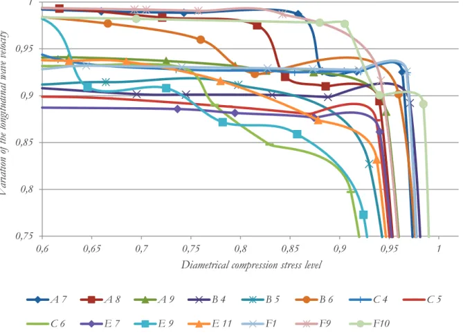
Figures 6 and 7 show the behavior of the longitudinal and trans-verse wave for all concrete samples submitted to the split test.
A first and significant observation for the results obtained from the
tensile tests is that the two waves, longitudinal and transverse, dropped in the velocities close to the tensile strength of the con-crete. This drop in velocities shows the capacity of the ultrasonic
pulses to detect the formation of the crack from stress inside the
samples during load application. It should be emphasized that, in
the tensile by diametrical compression tests, unlike the finding in the uniaxial compression test, there is no diffuse damage (resulting from microcracking); the damage associated with the diametrical
compression is local: formation of plane strain and later of a
ten-sile crack, perpendicular to the wave propagation. Thus, the tests showed that, in addition to being fully applicable to check for dif -fuse damage in concrete, the UPV test can also be used to
evalu-ate concentrevalu-ated damage – formation of a crack resulting from
applied stress. Furthermore, the most sudden and sharpest drop in pulse velocities when close to tensile strength, indicates the
sud-den nature (not progressive) of the formation of tensile cracking.
Again, the ultrasonic pulses appear to fully apply to evaluating the
formation of tensile cracking – even though such formation occurs
suddenly.
4. Conclusions
The level of mechanically imposed damage to the specimen from
applying stresses (unconfined compression or tensile by dia
-metrical compression) directly affects the propagation velocity of
the longitudinal and transverse ultrasonic waves in the concrete. Both types of ultrasonic wave used in the study revealed slower
Figure 6
Summary of longitudinal wave behavior in concrete samples subjected to split test
0,75
0,8
0,85
0,9
0,95
1
0,6
0,65
0,7
0,75
0,8
0,85
0,9
0,95
1
V
ar
iation
of
th
e longitu
dinal
wave
velocity
Diametrical compression stress level
A 7
A 8
A 9
B 4
B 5
B 6
C 4
C 5
velocities close to the failure load of the tested specimens. This drop in velocities shows the capacity of ultrasonic pulses to detect
the formation of tensile microcracking inside the samples when applying loads and detecting microcracking caused by uniaxial compression; hence, the test is efficient for samples undergoing
tensile and compressive loads, thereby evaluating the integrity of the material.
For local damage, as a result of diametrical compression (with the
formation of a tensile plane and, later, tensile crack, perpendicular
to the wave propagation), the tests showed that the UPV test is
ef-ficient in its evaluation. In the unconfined compression tests, how -ever, for the concrete samples tested, the propagation velocity of the longitudinal wave proved more sensitive to the level of stress applied, when compared to the transverse wave. In other words, the longitudinal ultrasonic wave more often used by researchers in this type of test best represents the reality and integrity of the tested
sample, and also detects any kind of void that might exist in the sample, probably due to the form of the wave’s propagation therein. The composition of the concrete influences the behavior of the
ultrasonic wave, whether longitudinal or transverse, and in addi-tion, it is very much worth considering the information of the water-cement ratio and concrete strength when analyzing the results of the UPV test.
The results overall for the two types of ultrasonic pulses used at-test to the feasibility of applying non-destructive ultrasonic at-tests
when examining the diffuse damage and concentrated damage in
the concrete.
Several studies are required in order to be able to learn about the behavior of the concrete in use through non-destructive tests. But
based on the results in this study, it is noticeable that the ultrasonic velocity is an extremely valuable test for the technological control of concrete, principally when correlated with the water-cement ra-tio, this datum being obtained at the start of mixing the concrete, since its strength will be obtained after 28 days and with the con-crete element in use.
5. Acknowledgments
The first author thanks Capes and CNPq for their financial support, essential for the conclusion of this major step forward. Also thanks
to Senai and Letmacc (Civil Construction Materials Technological Test Laboratory), especially to coordinator Ana Paula Alencar for
her friendship, efficiency and offering the laboratory to perform the
technological tests. Also to laboratory technicians David Macedo, Felipe Clayton and Nelson Martins for their vital help in carrying out the tests.
6. Bibliographic references
[1] POPOVICS, S.; ROSE, J. L.; POPOVICS, J. S. (1990): The behaviour of ultrasonic pulses in concrete, Cem Concr Res vol. 20, no. 2, pp. 259-270.
[2] NOGUEIRA, C. L.; WILLAM, K. (2001): Ultrasonic testing of
damage in concrete under uniaxial compression, ACI Mat J vol. 98, no. 3, pp. 265 – 275.
[3] QASRAWI, H. Y.; MARIE, I. A. (2003): The use of USPV to
anticipate failure in concrete under compression, Cem Concr Res vol. 33, no. 12, pp. 2017-2021.
Figure 7
Summary of transverse wave behavior in concrete samples subjected to split test
0,8
0,82
0,84
0,86
0,88
0,9
0,92
0,94
0,96
0,98
1
0,45
0,55
0,65
0,75
0,85
0,95
Variat
ion
of
the
transverse w
av
e veloc
ity
Diametral compression stress level
A 7
A 8
A 9
B 4
B 5
B 6
C4
C 5
[4] COLOMBO, Matteo; FELICETTI, Roberto. New NDT
tech-niques for the assessment of fire-damaged concrete structures.
Fire Safety Journal. Milan, Italy, p. 461-472. 21 Jun. 2007. [5] SILVA FILHO, Luis Carlos Pinto da et al. Estudos de caso
sobre avaliação de estruturas de concreto através da utiliza-ção de ensaios não destrutivos. Revista Alconpat, [s.l.], v. 1, n. 3, p.186-198, 30 set. 2011. Revista ALCONPAT. http:// dx.doi.org/10.21041/ra.v1i3.14.
[6] ASSOCIAÇÃO BRASILEIRA DE NORMAS TÉCNICAS. NBR 15575: Edificações habitacionais — Desempenho. Rio de Janeiro: ABNT, 2013.
[7] ANDREUCCI, Ricardo. Ensaio por ultrasom: Aplicação In-dustrial. São Paulo: Abende, 2008.
[8] ASSOCIAÇÃO BRASILEIRA DE NORMAS TÉCNICAS. 8953, 2015: Concreto para fins estruturais - Classificação
pela massa específica, por grupos de resistência e con-sistência. Rio de Janeiro, Brazil.
[9] ASSOCIAÇÃO BRASILEIRA DE NORMAS TÉCNICAS. 6118, 2014: Projeto de Estruturas de concreto, Rio de Ja-neiro, Brazil.
[10] KNAB, L. I.; BLESSING, G. V.; CLIFTON, J. R. (1983):
Labo-ratory evaluation of ultrasonics for crack detection in con -crete, ACI Mat J vol. 80, no. 3, pp. 17-26.
[11] LORENZI, Alexandre et al. Avaliação da capacidade de de-tecção de falhas no concreto através do ensaio ultrassôni-co. Revista Alconpat, [s.l.], v. 7, n. 3, p.286-301, 29 set. 2017. Revista ALCONPAT. http://dx.doi.org/10.21041/ ra.v7i3.127.
[12] ASSOCIAÇÃO BRASILEIRA DE NORMAS TÉCNICAS. 8802, 2013: Concreto endurecido — Determinação da velo -cidade de propagação de onda ultrassônica, Rio de Janeiro. [13] METHA, P. K., MONTEIRO, P. J. M., “Concreto: Microestrutura,