A bi-dissipative damage model for concrete
Um modelo de dano bi-dissipativo para o concreto
a Department of Civil Engineering, Federal University of Goiás, Campus Catalão, Catalão, Goiás, Brazil; b School of Civil Engineering, Federal University of Goiás, Campus Goiânia, Goiânia, Goiás, Brazil.
Received: 25 May 2014 • Accepted: 15 Dec 2014 • Available Online: 03 Feb 2014
Abstract
Resumo
This work deals with an improvement of an anisotropic damage model in order to analyze reinforced concrete structures submitted to reversal loading. The original constitutive model is based on the fundamental hypothesis of energy equivalence between real and continuous media fol-lowing the concepts of the Continuum Damage Mechanics. The concrete is assumed as an initial elastic isotropic medium presenting anisotropy, permanent strains and bimodularity induced by damage evolution. In order to take into account the bimodularity, two damage tensors governing
the rigidity in tension or compression regimes are introduced. However, the original model is not capable to simulate the inluence of the previous
damage processes in compression regimes. In order to avoid this problem, some conditions are introduced to simulate the damage unilateral effect. It has noted that the damage model is agreement with to micromechanical theory conditions when dealing to unilateral effect in concrete material. Finally, the proposed model is applied in the analyses of reinforced concrete framed structures submitted to reversal loading. These numerical applications show the good performance of the model and its potentialities to simulate practical problems in structural engineering.
Keywords: damage mechanics, unilateral effect, concrete structures, structural failure.
Este trabalho trata do aperfeiçoamento de um modelo dano anisótropo de modo a analisar estruturas em concreto armado submetidas à inversão
de carregamento. O modelo constitutivo original é baseado nas hipóteses fundamentais de equivalência de energia entre meio real daniicado e
meio contínuo equivalente segundo os conceitos da Mecânica do Dano no Contínuo. O concreto é assumido como um meio inicialmente elástico
e isótropo que passa a apresentar comportamento mecânico anisótropo, plástico e bimodular induzidos pelos processos de daniicação. Com o
intuito de se levar em conta a bimodularidade do meio, são propostos dois tensores de dano governando a rigidez em regimes de tração e de
compressão. Entretanto, o modelo original não é capaz de simular a inluência de processos prévios de daniicação em regimes de compres -são. Objetivando contornar este problema, algumas condições são introduzidas no modelo para simular o efeito unilateral causado pelo dano. Observa-se que o modelo de dano está de acordo com as condições obtidas da Teoria Micromecânica quando tratando do efeito unilateral em materiais frágeis, como o concreto. Finalmente, o modelo de dano proposto é aplicado na análise de estruturas de pórticos de concreto armado submetidas a cargas com inversão de sinal. Os resultados comprovam o bom desempenho do modelo e potencialidades para simular problemas práticos da Engenharia Estrutural.
Palavras-chave: mecânica do dano, efeito unilateral, estruturas de concreto, falha estrutural.
J. J. C. PITUBA a
W. M. PEREIRA JÚNIOR b
1. Introduction
The Continuum Damage Mechanics (CDM) has already proved to be a suitable tool for simulating the material deterioration in equivalent continuous media due exclusively to microcracking process. In this work, for modeling the concrete behavior, it can be assumed that the concrete belongs to the category of ma-terials which can be considered initially isotropic and unimodu-lar presenting different behaviors in tension and compression when damaged. A formulation of constitutive laws for isotropic and anisotropic elastic materials presenting different behav-iors in tension and compression under small deformations was proposed in Curnier [1] for two and three-dimensional cases. The authors have considered a bimodular hyperelastic materi-al defining an elastic potentimateri-al energy density W which must be once continuously differentiable (whole wise), but only piece-wise twice continuously differentiable. In this way, the model is able to produce different response in tension and compres-sion. Pituba [2] has extended that formulation in order to take into account the damage effects. Accordingly with, the bulk (λab) and shear (µa) moduli are considered as functions of the damage state, so that the stress-strain relationship would be influenced by damage variables. Moreover, the hypersurface g(ε, Di) adopted as the criterion for identification of the consti-tutive responses in compression or tension would be also influ-enced by the damage variables. Then, a damage constitutive model accounting for induced anisotropy and bimodular elastic response for the concrete was derived from Pituba [2] and its potentialities for 1D and 2D analyses are discussed in Pitu-ba [3], PituPitu-ba and Fernandes [4], PituPitu-ba and Lacerda [5] and Pituba [6]. Besides, the simulations of experimental tests in uniaxial, biaxial and triaxial stress tests are reported in Pituba and Fernandes [4]. The original version of the damage model is bimodular in the sense that presents different elasticity ten-sors in tension and compression. Thus, the model is potentially capable to simulate the stiffness recovery when the medium is submitted to a reversal loading that evidences the transi-tion from predominant regimes of tension to compression, i. e., the so-called unilateral behavior of the damaged concrete. However, the model is not capable to simulate the influence of the previous damage processes in compression (diffuse dam-age) when there is the transition from predominant regimes of compression to tension Comi [7]. From a micromechanics point of view this characteristic is due to the partial closure of micro-cracks loaded in compression which affect less the elasticity moduli in compression than in tension, Desmorat [8]. Therefore, to avoid this problem a new elasticity tensor is pro-posed and some numerical analyses are performed to simulate practical problems in structural engineering.
Many different strategies are possible and have been proposed in the literature to model the stiffness recovery as described in Comi [7], Carol and Willam [9], Welemane and Comery [10], Bielski et al. [11], Liu [12] and Araújo and Proença [13]. For more details, in Bielski [11] is presented a summary of some formulations of models that take into account the unilateral effect of the damage process, such as: the use of fourth-rank projection operators for the decomposition of the stress and strain tensors into the posi-tive and negaposi-tive projections, besides the use of the generalized projection operators.
On the other hand, despite the progresses in the macroscopic model-ing of the unilateral effect (in particular, the continuity problems that arise when the induced anisotropy is simultaneously described), this
subject still remains as an open research ield when it deals with in -duced anisotropy damage models, even when the micromechanical theory has been used to justify the proposal of constitutive models dealing with cracked media, Welemane and Comery [10], Zhu [14], Zhu [15] and Pichler and Dormieux [16]. This can be noted even when dealing with more actual approaches based on multi-scale analysis procedures, Skarzynski and Tejchman [17] and Pituba and Souza Neto [18]. Indeed, this work intends to contribute to the modeling of damage unilateral effect applied to concrete structures. However, it must be noted that the proposed model is not capable to take into account the friction effects, namely blocking and dissipative sliding of closed microcrack lips. This feature can be discussed in future works.
2. Bi-dissipative plastic-damage model
2.1 Original proposal of Pituba and Fernandes [4]
The original damage model formulation Pituba and Fernandes [4] is built from the formalism presented in Pituba [2]. Moreover, the model respects the principle of energy equivalence between dam-aged real medium and equivalent continuous medium established
in the CDM. The damage model is briely presented in this work.
Initially, for dominant tension states, a damage tensor is proposed:
(1)
D
T=f1(D
1,D
4,D
5)
(
A
Ä
A
)
+
2f
2(D
4,D
5)
[(
A
Ä
I
+
I
Ä
A
)
-
(
A
Ä
A
)]
-where f1(D1, D4, D5) = D1 – 2 f2(D4, D5) and f2(D4, D5) = 1 – (1-D4) (1-D5). The variable D1 represents the damage in direction orthog-onal to the transverse isotropy local plane of the material, while D4 is representative of the damage due to the sliding movement between the crack faces. The third damage variable, D5, is only activated if a previous compression state accompanied by damage has occurred. In Curnier [1], the tensor I is the second-order iden-tity tensor and the tensor A, is formed by dyadic product of the unit vector perpendicular to the transverse isotropy plane for himself. Those products are given in Pituba [2]. For dominant compression states, it is proposed the other damage tensor:
(2)
D
C=
f (D
1* 2,D
4,D
5)
(
A
Ä
A
)
+f
2(D
3)
[(
I
Ä
I
)
-)]
(
A
Ä
A
+2f
3(D
4,D
5)
)]
(
)
[(
A
Ä
I
+
I
Ä
-A
-
A
Ä
A
On the other hand, the constitutive tensor is written as:
(3)
E (
e
) :=
î
í
ì
+-)
(
E
)
(
E
e
e
if
if
g
g
,
0
)
D
,
D
,
(
,
0
)
D
,
D
,
(
C T C T>
<
e
e
(4)
=
+
(
e
)
E
11[
I
I
]
2
1[
I
I
]
-Ä
+
Ä
m
l
-)
D
,
D
,
D
(
1 4 522
+
l
[
A
Ä
A
]
- l
12+(
D
1)
[
A
Ä
I
+
I
Ä
A
]
)
D
,
D
(
4 5 2m
-
[
A
I
I
-A
]
--
+
Ä
Ä
(5)
=
-
(
e
)
E
11[
I
I
]
2
1[
I
-I
]
-Ä
+
Ä
m
l
-)
D
,
D
,
D
,
D
(
2 3 4 522
-l
[
A
Ä
A
]
- l
12-(
D
2,
D
3)
[A
Ä
I+I
Ä
A]
- l
11-(
D
3)
[I
Ä
I]-)
D
(
)
2
1
(
3 11 0 0-l
n
n
[I
Ä
I]
-
m
2(
D
4,
D
5)
[
A
I
I
-A
]
--
+
Ä
Ä
The remaining parameters will only exist for no-null damage, evidencing the anisotropy and bimodularity induced by damage. Those parameters are given by:
(6)
)
D,
D(
2
)
D(
2
)
D
D2
)(
2
(
)
D,
D,
D(
1 4 5 0 0 1 21 12 1 2 4 522
=
l
+
m
-
-
l
-
m
l
+ +1 0 1 12
D(
)
=
l
D
l
+;
D(
D,
)
2
1[
1(
D
)
1(
D
2])
5 2 4 0 5 42
=
m
-
-
-m
)
(
)
(
)
,
(
)
)(
(
)
,
,
,
(
11 30 0 3 2 12 2 2 2 0 0 5 4 3 2
22
D
D
D
D
2
D2
D
2
-D
D
1
-D
-
=
+
-
-
+
-
l
n
n
l
m
l
l
-
2
m
2(
D
4,
D
5)
)]
D
1)(
D
1(
)
D
1[(
)
D,
D(
2 3 0 32 2 312
=
l
-
-
-
-l
-;
D(
)
(
D2
D
2)
3 3 0 3 11
=
l
-l
-As it can see, the constitutive model includes two damage tensors in order to take into account the bimodularity induced by damage in the concrete behavior. Therefore, it is necessary a criterion to
deine the tension and compression dominant states to indicate
what damage tensor should be used.
The criterion has been extended in Pituba [2] in order to the actual
damage state can inluence on the hyperplane deinition. There -fore, the following relationship has been proposed:
(7)
g(
e
,D
T,D
C) = N(D
T,D
C) .
e
eIn Pituba and Fernandes [4], a particular form is adopted for the hypersurface in the strain space: a hyperplane g(ε) deined by the unit normal N (||N|| = 1) and characterized by its dependence of the strain and damage states. Accordingly with Eq. (7) and referring to general cases of loading, the following relationship has been pro-posed for the hyperplane:
(8)
g(
e
,D
T,D
C) = N(D
T,D
C) .
e
e=
g
1(D
1,D
2)
e
Ve+
g
2(D
1,D
2)
e
11ewhere γ1(D1,D2) = {1+H(D2)[H(D1)-1]}η(D1)+{1+H(D1)[H(D2)-1]}
η(D2) and γ2(D1,D2) = D1+D2.
The Heaveside functions employed above are given by:
(9)
H(Di) = 1
to
Di > 0;H(Di) = 0
to
Di = 0 (i = 1, 2)
The η(D1) and η(D2) functions are deined, respectively, for the tension
and compression cases, assuming for the irst one that there was no
previous damage in compression affecting the present tension damage variable D1 and analogously, for the second one that has not had previ-ous tension damage affecting variable D2. The proposed functions are:
(10)
h
(D
1) =
3
D
2
3
D
2 11
+
-(11)
h
(D
2) =
3
D
2
3
D
2 22
+
-Note that if the damage process in the material is not activated (D1 = D2 = 0) the Eq. (8) recovers the equation proposed by Comi [7], thus
the formulation satisies the proposed condition of initially isotropic
material. Already, if the material is totally damaged, D1 = D2 = 1 (η (D1) = η (D2) = 0) and γ2 = 2, the hyperplane g(ε) is coincident to the trans-verse isotropy local plane of the material and, therefore, the normal vector to the hyperplane is given by the transverse isotropy tensor A. On the other hand, due to anisotropy induced by damage, it is
con-venient to separate the damage criterion into two criteria: the irst
one is only used to indicate the beginning of the damage processes, or that the material is no longer isotropic; the second one is used for loading and unloading processes, when the material is already considered as transverse isotropic medium. This second criterion
identiies if there is or not evolution of the damage variables. That division is justiied by the difference between the complementary
elastic strain energies of isotropic and transverse isotropic materials. If there is damage evolution, i. e., when
D
T≠
0
orD
C≠
0
, the evolution laws of the damage variables are written as associated vari-ables functions. Considering just the case of monotonic loading, the evolution laws proposed for the scalar damage variables are resultingof ittings on experimental results. The general form proposed is:
(12)
[
B
(
Y
Y
)
]
exp
A
A
1
1
D
i 0 i i i iof energy equivalence, for the uniaxial point of view, for instance, the constitutive tensor is written as:
(13)
0
E
E
T=
1(
-
D
1)
21(
-
D
2)
2The relationship above shows that in tension dominant states pre-vailing prior to activation of damage in compression is possible to solve the problem discussed here. By analogy, under multiaxial stress states, it can be concluded that damage tensor in compres-sion DC should compose the expression of the constitutive tensor in tension dominant states. Therefore, respecting the principle of equivalence of energy, the constitutive tensor is now written as:
(14)
)
D
I
)(
D
I
(
E
)
D
I
)(
D
I
(
E
T=
-
C-
T 0-
T-
Cwhere Ai, Bi and Y0i are parameters of the model that must be
iden-tiied through the uniaxial tension and compression tests and bi -axial compression tests.
When the damage process is activated, the formulation starts to involve the tensor A that depends on the normal to the transverse isotropy plane. Therefore, it is necessary to establish some rules to identify its location for an actual strain state. Initially, it is estab-lished a general criterion for the existence of the transverse isot-ropy plane. In Pituba and Fernandes [4] is proposed that the trans-verse isotropy due to damage only arises if positive strain rates exist at least in one of the principal directions. After assuming such
proposition as valid, some rules to identify its location are deined.
2.2 Discussion about the unilateral effect
in brittle materials
The original version of the damage model is bimodular, however it is necessary to take into account the diffuse damage generated in previous compression regimes when dealing with tension regimes. This problem can be solved by introduction of a new elasticity ten-sor in tension dominant states. Therefore, respecting the principle
Considering a matrix representation and assuming, for instance, that the transversal isotropy local plane is coincident to the 2–3 plane, the constitutive tensor ET may be described as follows:
(15)
ú ú ú ú ú ú ú ú û ù ê ê ê ê ê ê ê ê ë é -+ -+ -+ = 4 5 4 4 0 4 5 4 4 0 0 2 3 0 0 2 3 0 3 2 1 0 2 3 0 2 3 0 0 3 2 1 0 3 2 1 0 3 2 1 0 2 2 2 1 0 0 1 1 2 0 0 0 0 0 0 1 1 2 0 0 0 0 0 0 2 0 0 0 0 0 0 1 2 1 1 1 1 0 0 0 1 1 2 1 1 1 0 0 0 1 1 1 1 1 1 1 1 2 ) ( ) ( ) ( ) ( ) )( (( ) ( ) )( )( ( ) ( ) )( ( ) )( )( ( ) )( )( ( ) )( )( ( ) ( ) )( ( D D D D D D D D D D D D D D D D D D D D D D ET m m m m l l l l m l l l l m lIt can be noted that the equations (5) and (11) present different values for the shear moduli in compression and tension domi-nant states, respectively. Therefore, this alternative formulation in order to take into account the diffuse damage does not re-spect the Curnier´s condition about the tangential continuity. To avoid this problem, another expression for the damage tensor in compression dominant states
D
*C is proposed. This tensor isgiven by:
(16)
* C
D
=f
1(D
2,)
(
A
Ä
A
)
+f
2(D
3)
[(
I
Ä
I
)
-
(
A
Ä
A
)]
-where f1(D2) = D2 and f2(D3) = D3. It is important to observe that the damage tensor
D
*C provides the diffuse damage inprevi-ous compression states through the changing of the volumetric modulus, as proposed in Comi [7]. For simplicity, considering a matrix representation and assuming, for instance, that the
trans-versal isotropy local plane is coincident to the 2–3 plane, equation (16) is written as:
(17)
ú
ú
ú
ú
ú
ú
ú
ú
û
ù
ê
ê
ê
ê
ê
ê
ê
ê
ë
é
=
0
0
0
0
0
0
0
0
0
0
0
0
0
0
0
0
0
0
0
0
0
0
0
0
0
0
0
0
0
0
0
0
0
3 3 2D
D
D
D
C*Finally, taking into account the principle of energy equivalence, the constitutive tensor for tension dominant states is given by:
(18)
)
D
I
)(
D
I
(
E
)
D
I
)(
D
I
(
E
* C T 0 T * C-Then, following the formalism presented in Pituba [2], the bidissipative anisotropy damage model taking into account the unilateral effect in brittle materials is written as:
Now, the parameters λij and µi are given by:
(19)
ú ú ú ú ú ú ú ú û ù ê ê ê ê ê ê ê ê ë é -+ -+ -+ = 2 5 2 4 0 2 5 2 4 0 0 2 3 0 0 2 3 0 3 2 1 0 2 3 0 2 3 0 0 3 2 1 0 3 2 1 0 3 2 1 0 2 2 2 1 0 0 1 1 2 0 0 0 0 0 0 1 1 2 0 0 0 0 0 0 2 0 0 0 0 0 0 1 2 1 1 1 1 0 0 0 1 1 2 1 1 1 0 0 0 1 1 1 1 1 1 1 1 2 ) ( ) ( ) ( ) ( ) )( (( ) ( ) )( )( ( ) ( ) )( ( ) )( )( ( ) )( )( ( ) )( )( ( ) ( ) )( ( D D D D D D D D D D D D D D D D D D D D D D ET m m m m l l l l m l l l l m l(20)
W(
e
)=
ry
(
e
)
î
í
ì
=
+-W
W
:
)
(
)
(
e
e
if
if
g
g
,
0
)
,
,
(
,
0
)
,
,
(
>
<
C T C TD
D
D
D
e
e
(21)
W+=ry
+(e)= 11tr
22
l
(e)
tr
(
1
m
+
e
2)-2
)
D
,
D
,
D
,
D
,
D
(
1 2 3 4 5 22+
l
tr
2(
A
e)-
l
+12
(D1,D2,D3)tr(e)tr(
A
e)
2
)
D
(
3 11--
l
tr
2(
e
)
(
D
)
tr
[(
2
)
2
1
(
3 11 0 0--
l
n
n
I
Ä
I
)
e
]
2-
m
2(
D
4,
D
5)
tr(
A
e
2)
(22)
W
-=
ry
-(
e
)=
l
2
11tr
2(
e
)
+
m
1tr
(
e
2)-
22(
D
2,
D
2
3,
D
4,
D
5)
-l
tr
2(A
e
)-
-12
l
(D
2,D
3)tr(
e
)tr(A
e
)
2
)
D
(
3 11--
l
tr
2(
e
)
(
D
)
tr
[(
2
)
2
1
(
3 11 0 0--
l
n
n
I
Ä
I
)
e
]
2(
D
,
D
)
5 4 2m
-
tr(
Ae
2)
(23)
)
D
D
2
)(
2
(
)
D
,
D
D
,
D
,
D
(
2 1 1 0 0 5 4 , 3 2 122
=
+
-+
l
m
l
)
D
(
)
1
(
)
D
,
D
(
2
)
D
,
D
,
D
(
2
11 30 0 5 4 2 3 2 1 12 -+
-
+
--
l
n
n
m
l
+
(
l
0+
2
m
0)(
[
1
-
D
1) (
2-
1
-
D
1) (
21
-
D
2)
2]
(
) (
)(
)(
)
[
3 2 1 2 3]
0 3 2 1
12
(
D
,
D
,
D
)
=
1
-
D
-
1
-
D
1
-
D
1
-
D
+
l
l
]
)
D
1
(
)
D
1
(
1
[
2
)
D
,
D
(
2 5 2 4 0 5 42
= m
-
-
-m
)
D
,
D
(
2
)
D
D
2
)(
2
(
)
D
,
D
,
D
,
D
(
2 3 4 5 0 0 2 22 12 2 322
--
=
l
+
m
-
-
l
l
)
D
,
D
(
2
)
D
(
)
1
(
5 4 2 3 11 00
l
m
n
n
-+
-)]
D
1
)(
D
1
(
)
D
1
[(
)
D
,
D
(
2 2 33 0
3 2
12-
=
l
-
-
-
-l
)
D
D
2
(
)
D
(
2 3 3 0 311
=
--
l
The stress tensor is obtained from the gradient of the elastic potential, as follows:
The constitutive tensor is also obtained from the elastic potential, i. e.:
Taking into account the unilateral effect and assuming that direction 1 be perpendicular to the transverse isotropy local plane in the strain space, the complementary elastic energy of the damaged medium in tension dominant states is now expressed by:
(24)
s
(
e
)=
î
í
ì
=
=
+-)
(
)
(
e
s
e
s
+-Ñ
Ñ
ry
ry
e e)
(
)
(
e
e
if
if
g
g
,
)
D
,
D
,
(
,
)
D
,
D
,
(
C T C T0
0
>
<
e
e
(25)
+s
(
e
)=
l
11tr
(
e
)
I
+
2
m
1e
-
l
+22(
D
1,
D
2,
D
3,D
4,
D
5)
tr (
A
e
)
A
-
l
+12(
D
1,
D
2,
D
3)
(tr(
e
)
A
+
tr(
A
e
)
I
)
- l
11-(
D
3)
tr (
e
)I
(
1
2
)
11(
D
3)
0 0--
l
n
n
(I
Ä
I)
e
-
m
2(
D
4,
D
5)
(A
e
+
e
A)
(26)
-s
(
e
)=
l
11tr
(
e
)
I
+
2
m
1e
-
l
-22(
D
2,
D
3,
D
4,
D
5)
tr(
A
e
)
A
-
l
-12(
D
2,
D
3)
(tr (
e
)
A
+ tr(
A
e
)
I
)
)
D
(
3 11-- l
tr (
e
)I
(
1
2
)
11(
D
3)
0 0--
l
n
n
(I
Ä
I)
e
-
m
2(
D
4,
D
5)
(A
e
+
e
A)
(27)
E
(
e
):=
î
í
ì
=
=
+-)
(
E
)
(
E
e
e
+-Ñ
Ñ
ry
ry
e e 2 2)
(
)
(
e
e
if
if
g
g
,
)
D
,
D
,
(
,
)
D
,
D
,
(
C T C T0
0
>
<
e
e
(28)
=
+(
)
E
e
E
T=
l
11[
I
Ä
I
]
+
2
m
1[
I
Ä
I
]
- l
22+(
D
1,
D
2,
D
3,
D
4,
D
5)
[
A
Ä
A
]
)
D
,
D
,
D
(
1 2 312
+
- l
[
A
Ä
I
+
I
Ä
A
]
- l
11-(
D
3)
[
I
Ä
I
]-
(
1
2
)
11(
D
3)
0 0-l
n
n
[
I
Ä
I
]
-
m
2(
D
4,
D
5)
]
A
I
I
A
[
Ä
+
Ä
(29)
=
-
(
)
E
e
E
C=
l
11[
I
Ä
I
]
+
2m
1[
I
Ä
I
]
- l
-22(
D
2,
D
3,
D
4,
D
5)
[
A
Ä
A
]
(
D
,
D
)
3 2 12
-- l
[
A
Ä
I
+
I
Ä
A
]
- l
11-(
D
3)
[
I
Ä
I
]-
(
1
2
)
11(
D
3)
0 0-l
n
n
[
I
Ä
I
]
-
m
2(
D
4,
D
5)
[
A
Ä
I
+
I
Ä
A
]
(30)
2 3 0 2 33 2 22 2 2 2 1 0 2 11 e)
D
1
(
E
2
)
(
)
D
1
(
)
D
1
(
E
2
W
-+
+
-=
+*
s
s
s
2 3 0 33 22 0 3 2 1 0 33 11 22 11 0
)
D
1
(
E
)
D
1
)(
D
1
)(
D
1
(
E
)
(
-+
-
n
s
s
s
s
n
s
s
2 23 0 0 2 13 2 12 2 5 2 4 0 0
E
)
1
(
)
(
)
D
1
(
)
D
1
(
E
)
1
(
n
s
The variables associated to damage variables in tension with
dam-age activated in previous compression will also be modiied, be -cause they are obtained from the elastic potential (20). Therefore, the following relationships are valid:
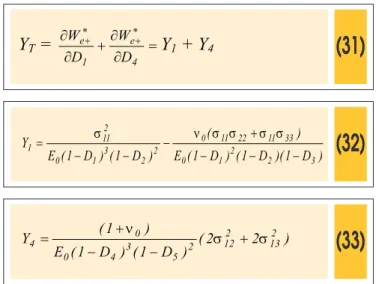
(31)
Y
T=
+
=
*+ *
+
4 e 1 e
D
W
D
W
Y
1
+ Y
4(32)
)
D
1
)(
D
1
(
)
D
1
(
E
)
(
)
D
1
(
)
D
1
(
E
Y
3 2 2 1 0
33 11 22 11 0 2 2 3 1 0
2 11 1
-+
-=
s
n
s
s
s
s
(33)
)
2
2
(
)
D
1
(
)
D
1
(
E
)
1
(
Y
213 2 12 2 5 3 4 0
0
4
n
s
+
s
-+
=
Note that only Y1 must to take into account the diffuse damage represented by D2 and D3. In this case, those damage variables are constants because there is no energy release rates during the damage evolution in tension dominant states related to D2 and D3. In the case of tension dominant states without activation of dam-age processes in previous compression, the original version of the damage model is recovered.
It can be veriied that the unilateral damage model satisies two
basic requirements of this modeling kind:
The model does not produce spurious energy dissipation upon closed load paths which do not activate damage, Matallah and La Borderie [19].
The continuity of the stress-strain law across the tension-com-pression interface is assured (hiperplano g(ε,DT,DC)), because the damage model is derived from the formulation proposed in Pituba [2], following the requirements of Curnier [1] and Welemane and Comery [10]. The continuity of the stress-strain law between two damage states imposes that the elastic potential must be once continuously differentiable (whole wise), but only piecewise twice continuously differentiable.
Accordingly with Curnier [1], other problem related to this kind of modeling concerns the loss of isotropy of the elasticity tensor in the transition through the tension-compression interface. The isotropy is
preserved only if the interface is deined in the same group of sym -metry of the elasticity tensor. In the proposed model the hyperplane and elasticity tensor belong to the group of isotropic material if there is not damage process. On the other hand, if there is activation of dam-age processes, the hyperplane starts to present the symmetry of the transverse isotropic material as well as the elasticity tensor. Anyway, the model always preserves the isotropy of the elasticity tensor.
2.3 Damage model applied in framed RC structures
This work intends to show the capabilities of the modiied dam -age model to simulate the mechanical behavior of reinforced con-crete structures submitted to reversal loading in possible practical situations of structural engineering. So, it is necessary that the
model presents eficient numerical responses, i. e., numerical
analyses with low computational cost and a few parameters of the
model to be identiied. Therefore, the one-dimensional version of the damage model has been implemented in a inite element code for bar structures analysis with inite layered elements in order to
model the reinforced concrete framed structures. For the longitu-dinal reinforcement bars, standard elastoplastic behavior is admit-ted. In the transversal section, a certain layer can contain steel and concrete, see Fig. 01. A perfect adherence between materials is adopted and an equivalent elasticity modulus and inelastic strain
are deined for each layer by using homogenization rule:
(34)
(
sk)
ck sk skk
C
E
C
E
E
=
1
-
+
(35)
(
sk)
cink sk pskink
C
e
C
e
e
=
1
-
+
where,
Considering the direction 1 as the longitudinal direction of the inite
element, the formulation presented in the previous item is
simpli-ied and presented as follows:
(36)
E
(
e
) :=
î
í
ì
=
=
+
-)
(
)
(
e
e
E
E
+ e
-e
ry
Ñ
ry
Ñ
2 2
)
(
)
(
e
e
if
if
g
g
,0
)
,
,
(
,0
)
,
,
(
>
<
C T
C T
D
D
D
D
e
e
(37)
2 2 2
1 0
T
E
1
D
1
D
E
=
(
-
)
(
-
)
(38)
2 2 0
C
E
1
D
E
=
(
-
)
(39)
2 2 2
1 0
2 11 e
2
E
1
D
1
D
W
)
(
)
(
-
-=
+
*
s
(40)
22 0
2 11 e
2
E
1
D
W
)
(
-=
-*
s
(41)
Y
T=
=
*+
1 e
D
W
Y
1
(42)
Y
C=
=
*
-2 e
D
W
Y
2
(43)
22 3
1 0
2 11
1
E
1
D
1
D
Y
)
(
)
(
-
-=
s
(44)
3 2 0
2 11
2
E
1
D
Y
)
(
-=
s
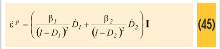
The one-dimensional version of the model takes into account per-manent strains induced by damage evolution. Assuming, for
sim-plicity, that the permanent strains are composed exclusively by vol-umetric strains, as it has already been considered in Comi [7], and taking into account the unilateral effect, the evolution law results:
(45)
=
pe
&
(
)
(
)
÷
÷
ø
ö
ç
ç
è
æ
-+
-
2 2 22 1
2 1
1
D
D
1
D
D
1
&
&
b
b
I
Observe that β1 and β2 are parameters directly related to the evo-lutions of permanent strains induced by damage in tension and in compression, respectively. The consideration of the permanent strains improves the capture of the transverse strains by the mod-el, as it can see in Pituba and Fernandes [4]. Besides, the model predicts the change in sign of the volumetric strain.
3. Micromechanical theory
Although the damage model has been based on the macrome-chanical behavior of the concrete, this item intends to show the strong connection between the model and the micromechanical theory. The description of the damage activation-deactivation pro-cess as part of macroscopic modeling requires knowing when the transition between these two states of damage occur and how damage deactivation affect the elastic properties of the material,
Welemane and Comery [10]. Moreover, there is a dificulty in rec -ognizing tension and compression states in 3D micro-scale analy-sis in order to adopt a differentiable Gibbs potential. It is noted that the formulation for bimodular anisotropic damaged media
pro-posed in Pituba [2] replies the irst question (see Equation (7)).
Besides, the continuity of the stress-strain law has been assured.
In this context, this section aims to point out the inluence of the
opening-closure of microdefects on the elastic properties of the microcracked concrete.
Following Welemane and Comery [10], consider a RVE (represen-tative volume element) of an homogeneous isotropic elastic linear matrix (Young modulus E0 and Poisson rate ν0) weakened by an
ar-ray of N randomly distributed lat penny-shaped microcracks (unit
normal nk, radius ak), whose radii are very small in comparison with
the size of the RVE. Assuming non-interaction among microcracks and sliding without friction of their lips, the free enthalpy of the mi-crocracked medium is given by:
(46)
u=
( )
( )
20 0 0 0
tr
E
2
tr
E
2
1
n
s
s
s
n
-×
+
( )
-
å
=-+
N 1 K 3 K 0 0 2 0a
E
2
1
V
3
8
s
:
n
n
(
)
( )
[
n
s
]
úû
ù
:
s
êë
é
Ä
+
Ä
- Ä-
-
-
Ä -Ä 4 k k n 0 2 k 2k
I
I
n
2
2
H
n
n
The Heaviside function H depending on the normal stress to each microcrack is open (
σ
kn≥
0
) or closed (σ
kn<
0
).Consider the simple case of a material weakened by a single array of parallel microcracks with unit normal n as in Fig. 2 and parameter A = 16A=16
( )
1−ν20 /(
6−3ν0)
. This case is interesting for the damage model proposed in this work because the effec-tive medium exhibits the symmetry associated with the geometric shape of the microcracks with the privileged direction n (transverse isotropic material).Then, the elastic moduli are fully determined by ive independent coeficients E(n), E(t), ν(n,t), ν(t,k) and μ(n,t), for any vectors t and k forming with n an orthonormal basis of R3. Using Eq (46), it can
be obtained the elastic moduli mentioned above.
(47)
( )
1N 1 K k n 0 3 k
0
1
V
A
a
(
2
)
H
E
)
n
(
E
-=ú
ú
û
ù
ê
ê
ë
é
-+
=
å
n
s
(48)
( )
1N 1 K k n 0 3 k
0
1
V
A
a
(
2
)
H
)
t,
n
(
-=ú
ú
û
ù
ê
ê
ë
é
-+
=
n
å
n
s
n
(49)
E(
t
) = E
0(50)
ν
(
t
,
k
) = ν0
(51)
(
)
1 N 1 K 3 k 00
1
1
A
V
a
)
t,
n
(
-=ú
ú
û
ù
ê
ê
ë
é
+
+
=
å
n
m
m
In Welemane and Comery [10] are described some conclusions about eqs (47)-(51) that are useful for a discussion about the proposed model. In general way, a macroscopic approach of the
unilateral effect in brittle materials should no longer be considered only by the single restoration of the Young modulus in the direction normal to closed microcracks. Therefore, based on micromechani-cal observations, some important aspects related to unilateral ef-fect of damage processes can be pointed out:
- The elastic moduli E(n) and Poisson ratio ν(n,t), related to nor-mal direction to parallel microcracks, are affected by the evolution of the microdefects. In particular, those moduli recover their initial values (E0 and ν0) when the microcracks are closed.
- In the other hand, the shear modulus μ(n,t) remains the same when the microcracks are closed (partial deactivation of damage). This behavior is consistent with the hypothesis about tangential jump null of the constitutive tensor. However, the elastic moduli E(m), ν(m,p) and μ(m,p) related to directions with different orienta-tions at principal axes (n,t and k) are partially recovered when the microcracks close.
The particular nature of the microdefects contribution allows ex-tending these considerations for any of N microcracks with differ-ent normal vectors. In this context, let us compare the damaged elastic moduli given by the proposed model to those ones given by the micromechanical equations. Then, considering Fig. 2 and assuming, for instance, that the transversal isotropy local plane is coincident with the 2-3 plane, the elastic moduli given by the pro-posed model in dominant compression (subscript C) and in tension (subscript T) regimes are written as:
(52)
2 2 2 1 0 1T
E
(
1
D
)
(
1
D
)
E
=
-
-
;
22 0 1
C
E
(
1
D
)
E
=
-(53)
(
3)
2 1 0 13 T 12
T
=
n
=
n
1
-
D
1
-
D
1
-
D
n
;
(
)
3 2 0 13 C 12
C
=
n
=
n
1
1
-
-
D
D
n
(54)
(
)
23 0 3 T 2
T
E
E
1
D
E
=
=
-
;
E
C2=
E
C3=
E
0(
1
-
D
3)
2(55)
0 23 C 23
T
n
n
n
=
=
(56)
(
) (
)
25 2 4 0 13 C 12 C 13 T 12
T
=
m
=
m
=
m
=
m
1
-
D
1
-
D
m
23 plane (transversal isotropy local plane) is not affected by the damage process. The shear moduli are not changed in the transi-tion from the tension to compression regimes and vice-versa. Ob-serve Eq. (54) and consider the transition from dominant tension regime (damage process in tension activated or not) to the com-pression regime without previous comcom-pression. In this case one has: ET2=ET3=EC2=EC3=E0. This result is in correspondence
with the form described by (49). Indeed, the
(
1−D3)
2coeficientis necessary to take into account the diffuse damage in previous compression when the current dominant state is tension.
Obviously, in general cases, when the damage process is activat-ed, the formulation starts to involve the tensor A, which depends on the knowledge of the normal to the transverse isotropy plane,
Pituba and Fernandes [4]. Therefore, the discussion about elastic moduli presented above is valid but that moduli are dependents of the tensor A, as described in item 2.1.
Finally, it is observed that despite the proposed model has mac-romechanical motivations in the macroscopic behaviour of the concrete, the model assists to the requirements suggested by We-lemane and Comery [10] for the micromechanical analysis of the unilateral effect in materials.
4. Numerical applications
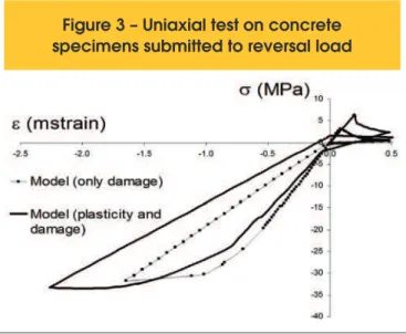
Initially, the unilateral model is used in the simulation of an uni-axial test in concrete specimens subject to reversal load in order to show the qualitative numerical response. Observe that the
per-manent strains are important in the deinition of the hyperplane, in
the sense that the total strains start to compose the criterion, Eq. (8). The initial stiffness recovery can be clearly observed taking into account permanent strain in the dominant tension regime. It is noted the contribution of the diffuse damage generated in previous compression regimes when dealing to tension regimes.
Figure 3 – Uniaxial test on concrete
specimens submitted to reversal load
Figure 4 – Geometry, reinforcement
details and loading history
4.1 Reinforced concrete beam with symmetric
reinforcement
This example deals with a test performed by La Borderie [20] and Matallah and La Borderie [19] that corresponds to a reinforced
concrete beam in a coniguration of three points cyclic lexion. The
beam is subject to cyclic loading at the middle of the span. The concrete has elasticity modulus Ec = 31,800 MPa; the steel has Es = 210,000 MPa, yielding stress of 445 MPa and ultimate stress of 540 MPa. In the experimental test, the beam is subjected to two
loading cycles of amplitude, the irst one is 1mm and the second
one 2 mm (see Fig. 4). The beam geometry and its reinforcement distribution are illustrated in Fig. 4.
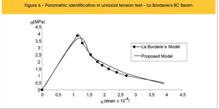
Figures 5 and 6 show the results of the parametric identiication of
the proposed damage model. The parameters used by La Borderie [20] were taken as reference in the simulation of uniaxial tension and compression tests. Table 1 presents the parameter values. It is important to note that the experimental tests do not present load-ing/unloading paths to identify β1 and β2. Therefore, the param-eters β1 and β2 have been adopted in order to obtain the perma-nent strains evidenced by the numerical analysis of the concrete beam during the unloading process. This adoption has been made without interference in the value of the compression and tension strengths of the concrete.
In the numerical analysis, displacements increments have been enforced in the middle of the span. Using the advantage of
sym-metry, only half of the beam has been discretized into 20 inite ele -ments. The transversal sections were divided into 16 layers where the reinforcement layers are located in the medium planes of the
second and ifteenth layers. In Fig. 7 are shown the numerical and
experimental responses of the vertical force and displacement in
the middle of the span related to the irst stage of the loading. It is
noted the good precision of the numerical response.
Figure 6 – Parametric identification in uniaxial tension test – La Borderie's RC Beam
Table1 – Parameters for the proposed damage
model – La Borderie’s RC Beam
Tension Compression
Y01 = 6.0x10⁻⁵ MPa Y
02 = 3.0x10 -3 MPa
A
1 = -0.93 A2 = 1.50
B
1 = 110 MPa
-1 B
2 = 10.01 MPa -1
β1 = 8x10
-5 MPa β
2 = 1.0x10 -3 MPa
In the other hand, in the Fig. 8 is illustrated the global response of whole test. The results obtained by the model are satisfactory
despite the limited parametric identiication of the parameters re -lated to permanent strains. The ultimate experimental loads re-lated
to the irst and second cycles are obtained by the both analyses:
when only damage processes are considered and the other one when permanent strains (b1 and b2) are taken into account too. However, the permanent strains in the unloading processes are only captured by the modelling with permanent strains, as expect-ed. In general way, the model reproduces satisfactorily the cyclic behaviour of the beam.
Besides, the damage proile is also close to experimental test ob -servations, see Matallah and La Borderie [19]. In Fig. 09 is shown the damage distribution in tension regimes at two points of the
curve illustrated in Fig. 08. The irst point is located at the end of the irst loading and the second one is located in the end of the
second loading (reversal loading). These distributions have shown
the opening/closure cracks process. The irst damage in tension