Original Article
Numerical analysis of truss systems with stiffened flattened end-bars
Abstract
Circular hollow sections are usually used in long-span roof truss systems. One of the typology for connecting elements in such structures involves the flattening of bar ends. This article presents the numerical analysis of a plane truss composed of circular hollow sections, in which diagonal bars have flattened ends. In this sense, a new flattening typology called stiffened flattening is proposed, characterized by a non-flat geometry, with the creation of stiffeners in the lateral edges of the diagonal flattened ends. The diagonal connecting system with the chord members uses connecting plates. The plates are welded to the chords and the diagonals are connected to latter through a single bolt. The numerical analysis using finite elements method was developed in two stages through ANSYS software with the Parametric Design Language (APDL), in which parameters such as geometry, materials, element types, boundary conditions and loads are specified. A non-linear analysis was performed using shell elements on the chords, diagonals, plates and welds, and contact elements between the diagonals with stiffened flattened ends and the connecting plates. Initially, a numerical study of the connecting node and the stiffened flattened end was performed, and the results directed the modeling of the plane truss. The numerical results were calibrated with the experimental truss results in full scale. The numerical result of the plane truss was also compared to a theoretical study, considering the axial load eccentricity applied in the diagonal with stiffened flattened ends. The study was based on the consideration of combined effects of axial force and bending moment provided by the Brazilian standard ABNT NBR 8800:2008. The final results indicate that the numerical model proposed is efficient and has good correlation with the experimental and theoretical results.
Keywords
Steel structures, plane trusses, numerical analysis, circular hollow sections.
1 INTRODUCTION
The industrial market has a wide variety of structural steel sections manufactured with standardized dimensions, where the professional may choose, for instance, the cross-sectional shape of the structural section that best suits his or her needs.
The hollow section presents excellent resistance capacity to the axial loads (tension and compression), torsion and combined effects. They can be used as composite structures (tubes filled with concrete), gaining additional resistance to compressive efforts and better protection against fire; they are also smaller compared to the open sections, which leads to lower painting costs, etc., thus facilitating maintenance services and minimizing their costs. (Requena and Santos, 2007).
Among the various types of structural systems, trusses have a diversified application, and their use in roof truss systems adds up an appearance of boldness and modernity, covering long spans with reduced self-weight, also presenting a good structural performance along with cost-effective solutions by means of fast execution and assembly. (Araújo et al., 2016).
Ana Amélia Mazon a
Arlene Sarmanho b*
Gabriel Nunes c
Lucas Roquete a
Luiz Henrique Neiva b
Flávio Souza d
a Departamento de Tecnologia em Engenharia Civil, Computação e Humanidades, Universidade Federal de São João del-Rei, Ouro Branco, Minas Gerais, Brasil. E-mail:
[email protected], [email protected]
b Departamento de Engenharia Civil,
Universidade Federal de Ouro Preto, Ouro Preto, Minas Gerais, Brasil. E-mail:
[email protected], [email protected]
c Departamento de Construções, Instituto Federal de Minas Gerais, Congonhas, Minas Gerais, Brasil. E-mail:
d Departamento de Construções, Instituto Federal de Minas Gerais, Ouro Preto, Minas Gerais, Brasil. E-mail: [email protected]
*Corresponding author
http://dx.doi.org/10.1590/1679-78254119
Received: June 14, 2017
Several types of connecting systems have been developed and used in truss structures. Among them, the patented connecting nodes, which have been experimentally evaluated and characterized in several countries. In Brazil, due to economic reasons, the most adopted connection uses in nodes are end-flattened bars connected by a single bolt. This type of joint is the simplest one and, therefore, cheaper to manufacture. However, there are two main disadvantages: the generated eccentricity force and reduction of the bar stiffness due to the end-flattening process. (Andrade et al., 2005).
According to Dutta et al. (1998), the main drawback of flattening the ends of circular hollow sections is the possible occurrence of cross-sectional and longitudinal cracks if the section is cold formed. The cold formed flattening of circular hollow sections is more feasible, since it is faster, simpler and more economical than hot flattening. There are several flattening methods. These include shearing, total flattening, flattening with controlled transition zone and partial flattening.
According to Dundu (2014), end flattening causes a variation of the moment of inertia, which implies the possibility of failure in the flattened ends of the member under compression, which is uncommon in the bars under compression load. Most standards do not provide prescriptions for sizing of flattened-end circular hollow sections or the reduction of the moment of inertia. Although flattening affects a small portion of the overall length of the element, this portion can be critical in determining its resistance capacity.
A large number of researches who deal with the various aspects of truss behavior, design, and construction is found in national and international literature, but few have a direct relationship with flattened-end tubular bars.
Maleci (1994), Ballerini et al. (1995), Posocco (1997) carried out researches that present basic guidelines for space truss projects, usage advantages and dissemination of new constructive technologies.
The overall influence of imperfections on the behavior of space structures was discussed by Schmidt, et al. (1976) and by Sadic & Abatan (1993).
Schmidt & Morgan (1982) and Collins (1984) conducted experimental trials with reduced models for behavioral assessment and analysis of failure modes. However, for the evaluation of connecting systems, in most cases the experimental tests are carried out in full scale, as those described in the works developed by El-Sheikh (1996) and Landolfo, et al. (1993).
The analysis of space trusses through finite elements considering parameters such as material and geometric nonlinearities, eccentricities in the initial connections and imperfections was studied by some researchers who developed models and techniques of analysis for this purpose, such as Smith (1984), Yang & Yang (1997), Liew et al. (1997), Madi (1984), Vendrame (1999), Sampaio (2004) and Nobre et al. (2015).
Grundy and Foo (1991), Eimanis (1993), Milani and Grundy (1997) and Dale et al. (2003) carried out experimental analyses for the evaluation of the behavior of connections involving flattened-end bars and compared them with profile-cut connections. Grundy and Foo's have observed that the connections involving flattened ends present greater resistance when compared to those involving profile-cut and welding, with a difference of 20% in peak strain concentration factors. Eimanis found that connections involving flattened ends are 52% stronger in compression and about 20% stronger in tension, compared to cut-off connections in profile. The studies performed by Milani and Grundy presented similar results to those of Eimanis and Dale et al.
Gonçalves et al. (1996), Gonçalves and Ribeiro (1996), Magalhães (1996), Malite et al. (1997), Malite, et al. (2001), Souza, et. al. (2002) and Dundu (2014) present researches that focus on the study of isolated flattened-end bars under compression. Different types of flattened-flattened-end bars were considered in each research and, in all of them, was observed a reduction in the resistance capacity concerning the compression in the bars due to the influence of the flattening.
Souza (1998) presented a numerical and experimental study of a space truss constituted by flattened-ends hollow section. The ruin of the structure was characterized by the collapse of connections, caused by excessive rotations of the nodes formed by the overlapping of flat ends, formation of plastic hinges in the connecting region, and relative sliding between bars. In their experimental results, D’Este (1998) and Maiola (1999) observed similar behavior to that presented by Souza (1998).
Ana Amélia Mazon et al.
Numerical analysis of truss systems with stiffened flattened end-bars
elements under compression due to the instability of the connection, and for some types of nodes, the buckling coefficient of the bars can exceed 1.3.
Souza (2003), Andrade, et al. (2005), Bezerra, et al. (2009), Freitas, et al. (2013) and Freitas, et al. (2017) analysed the structural behavior of steel space structures using flattened-ends hollow sections and evaluated the use of structural reinforcements in order to increase the resistant capacity of the structures. Some of them showed favorable behavior, others, on the other hand, did not achieve the purpose of reinforcement.
Mazon (2016) has conducted numerical, experimental and theoretical studies on the behavior of a plane hollow truss with flattened-end diagonals. A differentiated flattening was proposed, characterized by a non-flat geometry, with the creation of stiffeners on the lateral edges of flattened ends, called stiffened flattening. In relation to the theoretical values of Brazilian standards ABNT NBR 8800:2008 and ABNT NBR 16239:2013 – Design of steel and composite structures for buildings using hollow sections (ABNT, 2013), a 60% reduction in the resistance capacity of the flattened–end diagonals was observed.
2 NUMERICAL ANALYSIS
The main objective of this study is the numerical analysis of a plane truss behavior in which the flattened-end diagonals are fabricated with a new flattening typology, called stiffened flattening. The analysis was later calibrated with the experimental results presented in Mazon (2016). Numerical analysis was performed in two stages. Initially, there was the development of the numerical model of the connecting node whose conception is used in the plane truss. The preliminary results guided the realization of the second stage, characterized by the numerical modeling of the plane truss, followed by the calibration with experimental results.
The numerical models of the connecting node were simulated with nominal dimensions of circular hollow sections in structural steel without considering imperfections. The connecting node numerical analysis provided the definition of the circular hollow sections dimensions of the chords and the plane truss diagonals, as well as the size and thickness of the connecting plates.
With the definition of the connecting node and the final shape of the flattening, the numerical study of a plane truss was performed in which the behavior of the stiffened flattened-end diagonals leads to the mode of structure failure mode.
Through numerical modeling one can identify regions of stress concentration, displacements, failure modes, and the maximum load supported by the structure.
2.1 Numerical analysis of the connecting node
The numerical analysis of the connecting node was performed using finite elements with the ANSYS software, through the ANSYS Parametric Design Language (APDL), where parameters such as geometry, material definition, element types, boundary conditions, loads and other connection characteristics such as the variation of the moment of inertia of the stiffened flattened-ends of the bars, eccentricities, material and geometrical nonlinearities, and contact effects between the surfaces were involved.
Materials with nonlinear stress-strain relationship were used, with bilinear diagram, shell element in chords, diagonals, plates and welds, and contact elements between the stiffened flattened-ends of diagonals and the connecting plates.
2.1.1 Numerical model of the connection
An initial study of the stiffened flattening shape was conducted with reference to a hollow section of 76 mm in diameter and 2.0 mm thick, with the ends composed by the traditional straight flattening, as presented in Sampaio (2004). Geometries of cross-sections of the region influenced by the flattening were considered. The reference tube was sectioned according to Figure 1 (a).
Figure 1: Flattened ends. (a) Sectioning of the referred circular hollow bar flattened-end. (Sampaio, 2004). (b) Cross-sections of stiffened flattening.
It is noticeable a differential flattening characterized by a non-flat geometry with the creation of the stiffening on the lateral edges of the ends. The length of the flattened end, characterized by the distance between the two S1 sections that is considered more appropriate for the geometry adequacy of the bar is equal to 100 mm.
Figure 2 displays a view of the connecting system studied in the first step of the numerical analysis, modeled from the boundaries of the cross-sections of the chords and the diagonals, and from the geometry of the connecting plate and the weld, all data input in the ANSYS software. The lines delimit the considered areas for the construction of the model and definition of the meshes. The numerical model has a total number of 16109 nodes. It is a connection made up of circular hollow section elements wherein the stiffened flattened-end diagonals are attached to the connecting plate welded to the chord by a single bolt.
Figure 2: Geometry of the numerical model of the connecting node.
Ana Amélia Mazon et al.
Numerical analysis of truss systems with stiffened flattened end-bars
Through the input data that generated Figure 2 geometry, a model was analysed considering a circular hollow section with an external diameter of 88.9 mm and 4.8 mm of thickness in the chord, and another one with an external diameter of 38.0 mm and 3.0 mm of thickness on the diagonals. A square connecting plate of 120 mm side and 8 thickness was considered. The diameter of the plate holes and of the diagonals stiffened flattened-ends is equal to 17.5 mm. The dimensions chosen correspond to the result of the numerical study of the connection node that will be presented next.
The chosen and presented connecting typology that will be used in the plane truss composed of stiffened flattened-ends hollow bars follows a standardization of long span structures as studied in Requena et al. (2008).
According to previous works (Minchillo, 2011 and Nunes, 2012), the most suitable element for the connecting analysis presented in this work is the element SHELL181 (Figure 3), due to the low computational cost and good results regarding convergence. This element considers the effects of bending, shearing, and membrane, it has four nodes and six degrees of freedom per node, translation in x, y and z and rotation around x, y and z. SHELL181 was used in the modeling of all the constituent elements of the connection: chord, connecting plate, weld and diagonals.
Figure 3: SHELL181 (ANSYS, 2012).
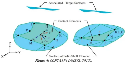
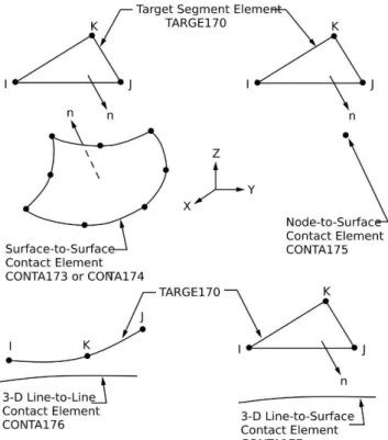
In the numerical modeling of the node, the contact effect between the connecting plate and the diagonals under tension or compression was considered. The contact element used in the modeling is the CONTA174, Figure 4, which represents the contact and the sliding between a target surface (TARGE170, Figure 5) and a deformable surface, defined by this element. In the present modeling, the connecting plate was used as the target surface and the diagonal areas involved in the contact as contact surfaces.
Figure 5: TARGE170 (ANSYS, 2012).
The numerical modeling used the material with a nonlinear stress-strain relationship, with a bilinear diagram and with the following mechanical properties: modulus of elasticity equal to 200 GPa, Poisson coefficient equal to 0.3, yield strength of the hollow sections equal to 300 MPa, yield strength of plate equal to 250 MPa and minimum weld metal tensile strength equal to 485 MPa. The stress-strain diagram was considered with elastic perfectly plastic material, Figure 6.
Figure 6: Schematic representation of the diagram bilinear stress-strain relationship used in the analyses
For the definition of the mesh, the use of the APDL language allows to grant elements the desired size and shape, enabling the comparison between models and the refinement in regions of stress concentration.
Ana Amélia Mazon et al.
Numerical analysis of truss systems with stiffened flattened end-bars
Figure 7: Representation of mesh. (a) Chord-plate-weld. (b) Stiffened-end diagonal.
The chord ends received displacement restrictions in the three directions (x, y and z). For the application of the boundary and loading conditions at the free diagonals ends, the nodes located in the last line of elements were rotated, with the arrangement of the x-axis in the longitudinal direction of the diagonals. The free diagonals ends received displacement restrictions in the directions y and z, referenced perpendicular to the longitudinal direction of the diagonal. Figure 8 shows the schematic of the boundaries conditions, as well as the axial loading direction applied.
Figure 8: General scheme of boundary conditions of the model and axial loading.
In order to simulate the bolt used in the connection, a coupling of the nodes corresponding to the first line of finite elements was performed in the boundaries of the holes. Figure 9 (a) illustrates the coupling of the nodes in the numerical model.
The loading was applied to the nodes belonging to the lines at the diagonals free, non-flat ends. One of the diagonals was requested by an axial compression load and the other, by an axial tension load, both of equal intensity. Figure 9 (b) and Figure 9 (c) show the loading application in the numerical model, identifying the diagonals under tension or compression.
2.1.2 Numerical results of the connecting node
The geometry and composition of the plane truss will be defined by the numerical results of the connecting node. The hollow sections of the chord and the size and thickness of the connecting plate will be varied, so as to evaluate a condition in which these two elements present superior resistance to the stiffened flattened-end diagonals, the focus of the study. Therefore, a situation is sought where the failure mode of the structure occurs on the diagonals stiffened flattened-ends.
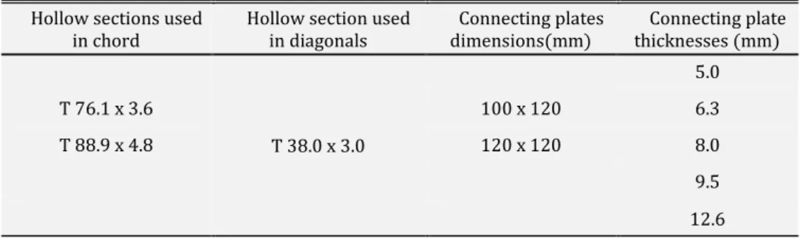
For the evaluation of the connecting performance by means of numerical analysis, parametric studies were performed, in which two circular hollow sections in different structural steel were considered for the chord and a third section for the diagonals. For the connecting plate, there are two dimensions with a variation of five thicknesses. Table 1 describes the characteristics considered for the elements.
The length of the flattening of diagonals ends, adopted equal to 100 mm, the length of the chord, adopted equal to 1000 mm, the diameter of the plate holes and the diagonals stiffened flattened-ends, equal to 17.5 mm, the angle of 45° between the diagonals and the plate and the applied loading of the same intensity on the diagonals under tension or compression, equal to 48 kN were kept constant in all analyses performed.
The materials characteristics of the hollow sections, the connecting plate and the weld were the same as mentioned above.
Table 1: Description of connecting components.
Hollow sections used in chord
Hollow section used in diagonals
Connecting plates dimensions(mm)
Connecting plate thicknesses (mm)
T 38.0 x 3.0
5.0
T 76.1 x 3.6 100 x 120 6.3
T 88.9 x 4.8 120 x 120 8.0
9.5
12.6
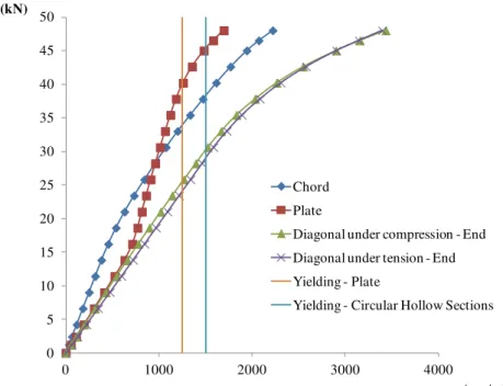
Figure 10 shows, for each element (diagonals, chord and plate), the first node in which the yielding stress is observed in all the performed numerical analyses. On the diagonals, this point is located on the lateral stiffener of the bar flattened end, in the transition from the circular cross-section to the stiffened flattening section, as shown in Figure 10 (a). In the hollow section of the chord the node is located in the region under compression by the connecting plate near the weld, Figure 10 (b).
Ana Amélia Mazon et al.
Numerical analysis of truss systems with stiffened flattened end-bars
Figure 10: First node in which the yielding stress is observed: (a) stiffened flattened-end diagonals, (b) chord, (c) connecting plate.
According to the obtained numerical results, the connection applied as reference for the composition of the plane truss was the connection of the model with circular hollow sections with external diameter of 88.9 mm and thickness of 4.8 mm in the chord, circular hollow section with external diameter of 38.0 mm and thickness of 3.0 mm on the diagonals and connecting plate with dimensions 120 x 120 mm and 8.0 mm thickness. In this model, the failure mode occurs in the stiffened flattened-end that allows the analysis of the influence of the new typology in a plane truss with the form of connection studied in the model.
0 5 10 15 20 25 30 35 40 45 50
0 1000 2000 3000 4000
P (kN)
ɛ (µm/m) Chord
Plate
Diagonal under compression - End Diagonal under tension - End Yielding - Plate
Yielding - Circular Hollow Sections
Figure 11: Load graph of the diagonal under compression versus von Mises strain.
The occurrence of the yielding stress on the lateral stiffener of the bar flattened end of the diagonals is observed at approximately 30 kN. In the chord and plate, the begin of the yielding stress corresponds to the loads of 38 kN and 40 kN, respectively. It is verified that the use of the larger hollow sections (diameter and thickness) and the square-shaped plate with a thickness of 8.0 mm meets the purpose of the study, since the failure occurs at the diagonals flattened ends.
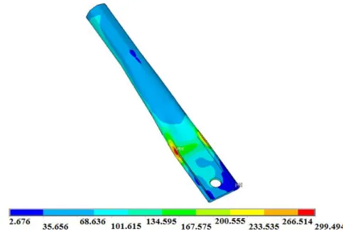
Figures 12, 13 and 14 present the results obtained for the von Mises stress distribution in the chord, in the diagonal under compression, and in the connecting plate, respectively, for the load of 30 kN, which corresponds to the occurrence of the yielding stress in the diagonal.
Ana Amélia Mazon et al.
Numerical analysis of truss systems with stiffened flattened end-bars
Figure 13: von Mises stress distribution (MPa) of the diagonal under compression for the load of 30 kN.
Figure 14: von Mises stress distribution (MPa) of the connecting plate for the load of 30 kN.
2.2 Numerical analysis of truss with stiffened flattened-ends
Numerical studies of the connecting node defined the stiffening of the flattened diagonals ends and the numerical model development of the plan truss. The numerical results of the plane truss were calibrated with the experimental results from Mazon (2016), that performed an experimental analysis of a plane truss in which the diagonals have stiffened flattened-ends and the geometry meets the composition directed by the numerical study of the connecting node.
2.2.1 Numerical model of the plane truss
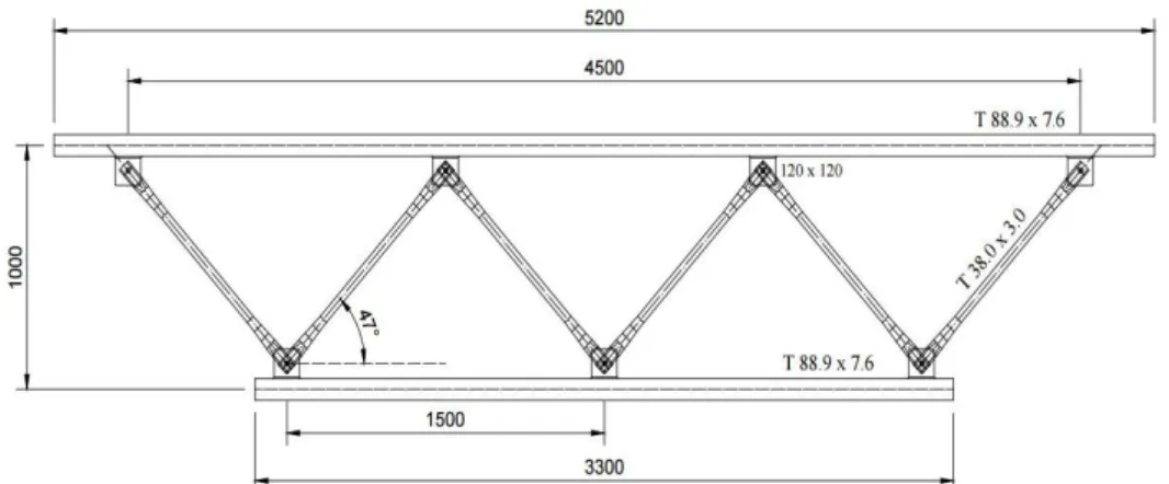
The height of the truss, measured from the centerlines between the chords is 1000 mm. The total length of the upper and lower chords is respectively, 5200 mm and 3300 mm. The total length of the flattened-end diagonals is 1150 mm, and the distance between the centers of holes is 1090 mm. The angle between the diagonals and the chords modified by the eccentricity between the axis of the hollow section of the chord and the center of the hole of the connecting plate is 47°. Figure 15 shows the described geometry.
Figure 15: Plane truss geometry. Dimensions in milimeters.
In order to facilitate the identification of the elements in the studied truss, the nomenclature indicated in Figure 16 will be used.
Figure 16: Identification of truss elements: Lower Chord (LC), Upper Chord (UC), Diagonals (D1, D2, D3, D4, D5 and D6) and Connecting Plates (P1, P2, P3, P4, P5, P6 and P7).
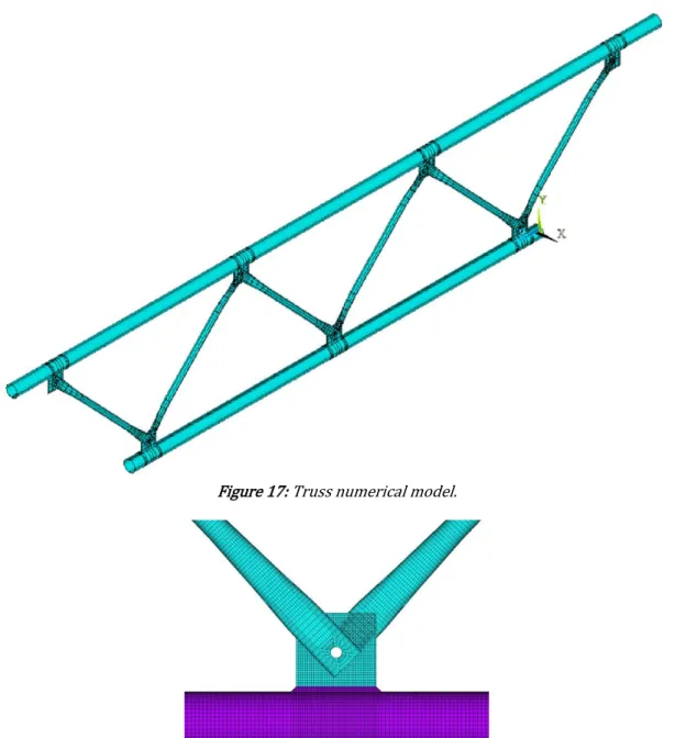
Among the main geometric variables defined in the APDL file for the numerical model, are the dimensions of the truss, such as total height, angles between chords and diagonals, total length of lower and upper chords, free length of chord ends, total length and distance between the holes of the diagonals and the distance between centers of holes of the connecting plates. Also included are the dimensions and thicknesses of the chords, diagonals, connecting plates and welds, and the distance between the sections of the diagonals stiffened flattened-ends. Variables were used to control the line division for the meshes definition in terms of the number of elements, that is, more or less refined.
Ana Amélia Mazon et al.
Numerical analysis of truss systems with stiffened flattened end-bars
Figure 17: Truss numerical model.
Figure 18: Details of the numerical model discretized of the central connecting node of the lower chord.
The shell finite element, the contact finite elements between the diagonals ends and the connecting plates, the type of analysis, the typology of the mesh used in the chords, diagonals, connecting plates and weld, and the coupling between the connecting elements were considered as presented in the numerical studies of the connecting node.
For the boundary and loading conditions, it was taken into account the load application in the two central nodes of the upper chord of the truss and the structure support at the upper chords ends.
For the truss support regions located in the lower part of the two ends of the upper chord, it was defined that, in order not to cause an excessive stress concentration, simulated supports were aligned in relation to the longitudinal axis of the chord, as shown in Figure 19 (a). The supports received displacement restrictions in the cross-section (x) and longitudinal (z) directions with respect to the truss plan, being that in the truss work point (PT) constraints were imposed in the cross section (x), vertical (and) and longitudinal (z). The ends of the lower chord received displacement restrictions in the direction perpendicular to the truss (x), Figure 19 (b).
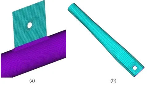
Figure 19: Boundary condition. (a) One of the supports of the truss at the upper chord. (b)End of the lower chord of the truss. (c) Load application on the central nodes of the upper chord.
2.2.2 Numerical analysis results of the plane truss
As in the preliminary analyses of the connecting node, the numerical results of the plane truss indicate that the first node in which the yielding stress is observed on the diagonals under compression D2 and D5 and the diagonals under tension D1 and D6 is located in the lateral region of the bar stiffened flattened end, in the transition of the circular cross-section to the section of the stiffened flattening, as indicated in Figure 10 (a).
The point of greatest stress concentration, evaluating the hollow sections of the lower and upper chords, is located in the regions under tension by the connecting plates P1 and P3, located at the ends of the lower chord, producing the same effect in both points due to the symmetry of the structure.
In the connection plates, it can be observed, as expected, that the most requested region is that of contact between the bolt and the hole. The strain measurement point was considered as shown on the connection node, Figura 10 (c).
Figure 20 shows the numerical results in the graph of total load, P, versus von Mises strain at the first node in which the yielding stress is observed in each of the plane truss components described, in addition to the strain relative to the yield stress in the plate and in the circular hollow sections of 1250 μm / m and 1500 μm / m, respectively, represented by the two vertical lines. The analyses presented are for a load applied to each of the two central nodes of the upper chord equal to 36 kN, that is, a total load, P, of 72 kN. It is observed that the yielding stress first occurs at the end of the diagonal under tension and later at the end of the diagonal under compression.
10 20 30 40 50 60 70 80 P (kN)
Lower chord Plate
Diagonal under compression Diagonal under tension Yielding - Plate
Ana Amélia Mazon et al.
Numerical analysis of truss systems with stiffened flattened end-bars
The behavior of the most loaded diagonals under compression D2 and D5 was observed in the numerical analysis of the plane truss, which showed, at first, the occurrence of the yielding stress in lateral edge of the stiffened flattened bar end, and as the load increased, the occurrence of the yielding stress could be observed half the bar length, in the region under compression, due to the lateral deflection that occurs because of the buckling of these elements, leading to the loss of the structure load capacity.
The graph of load versus von Mises strain of Figure 21 shows the results of the most loaded diagonals under compression D2 and D5 at three points located in specific regions, one in the lateral stiffener of the stiffened flattened bar end, and two others localized half the bar length, one in the region under compression and the other in the region under tension, due to buckling.
Figure 22 shows the von Mises stress distribution on the diagonal under compression for the load of 64 kN, which corresponds to the occurrence of the yielding stress at the point located half the diagonal length, and in the region under compression, due to the deflection derived from the buckling effect.
Through the numerical analysis it was possible to observe that the truss behavior led to a mechanism of the diagonals composed by the stiffened flattening of the ends. The occurrence of the yielding stress has been detected first at the ends of the diagonals under tension D1 and D6 and the diagonals under compression D2 and D5. With continuity of loading, the stress was redistributed and it was noticeable the occurrence of the yielding stress half the longitudinal length of the diagonals under compression D2 and D5 in the region under compression as a function of lateral deflection by the buckling of the bar, characterizing the failure of the structure.
0 10 20 30 40 50 60 70 80
0 1000 2000 3000 4000
P (kN)
ɛ (µm/m)
Diagonal under compression (End)
Diagonal under compression (Region under compression) Diagonal under compression (Region under tension) Yielding
Figure 21: Graph of load versus von Mises strain of diagonal under compression.
3 NUMERICAL MODEL VALIDATION
For the numerical model validation, the results obtained through numerical analysis were compared to experimental results presented in Mazon (2016). With respect to the instrumentation used in the experimental study of the full-scale truss model, unidirectional resistance strain gages were installed on the diagonals under compression D2 and D5, positioned half the longitudinal length, one in the region under tension and the other in the region under compression of the bar because of the lateral deflection derived from the buckling of the bars.
For the comparison with the experimental results, the numerical results of the plane truss are presented considering the mechanical properties of the diagonal circular hollow sections obtained through the material characterization tests by Mazon (2016), with the yield strength equal to 385 MPa and the ultimate stress of 545 MPa, and the nominal values of the constituent steels of the hollow sections of the chords and of the connecting plates, being the yield strength equal to 350 MPa and 250 MPa of the chords and plates, respectively. The minimum weld metal tensile strength is equal to 485 MPa. The material used in the numerical modeling was the one with tension versus non-linear deformation relationship, with bilinear diagram.
The results obtained by the numerical model are identified by FE in the graphs. The maximum load in the numerical and experimental analyses reached 84 kN and 86.5 kN, respectively. On the whole, the two analyses presented the same behavior.
Figure 23 (a) shows the lateral displacements obtained by the numerical model in which the deflection of the most loaded diagonals under compression D2 and D5 is observed. Figure 23 (b) shows the diagonal under compression D5 after the test. It can be seen that the numerical model represents the deformed shape of the diagonal as a result of the buckling representing its real behavior and, therefore, the failure mode of the truss.
Figure 23: Lateral displacements of the diagonal under compression. (a) Numerical model for the load of 84 kN. (b) View of the diagonal under compression after the experimental trial (Mazon, 2016).
The graph of Figure 24 shows the numerical and experimental results curves represented by the load versus
Ana Amélia Mazon et al.
Numerical analysis of truss systems with stiffened flattened end-bars
0 10 20 30 40 50 60 70 80 90
-3000 -2000 -1000 0 1000 2000 3000
P (kN) ɛ (µm/m) E11 E12 E13 E14 E11 e E13 - FE E12 e E14 - FE
Figure 24: Diagonals strain.
Comparing the experimental strain obtained by the strain gages E11 to E14 with the numerical results, one can observe a good correlation between the results, proving the efficiency of the numerical model to represent the real behavior of the truss component, the hollow diagonals with stiffened flattened-ends.
The numerical and experimental curves present the same tendency with similarity in the strain values throughout the trajectory, obtaining experimental and numerical results with the same order of magnitude. Thus, the numerical model indicates a correct prediction of ultimate load, behavior and failure mode of diagonals.
Table 2 shows the evolution of the stress distribution on the diagonal under compression, D5. It should be noted that in the numerical model, the occurrence of the yielding stress is observed in the diagonal mid-point and presents a tendency towards the bar ends.
In conclusion, the similarity of numerical and experimental results in terms of strain and displacements is evidenced, confirming the efficiency of the numerical model to represent the overall behavior of the structure.
Table 2: Evolution of stress distribution in diagonal under compression (D5).
Lo
ad (kN) 81 82 84
D ia gon al u nd er com p re ss io n, D 5 vo n Mis es st re ss crit erio n (M P a)
4 THEORETICAL PROPOSAL
ABNT NBR 16239: 2013 considers that the sizing of bars under compression load must be carried out in accordance with the requirements of ABNT NBR 8800: 2008. However, it presents a different buckling curve for determining the reduction factor associated with the axial compression load for tubular profiles.
The Brazilian standard ABNT NBR 8800: 2008 provides the expression for the computation of the axial compression strength of calculation given by
1 , a y g Rd c
f
QA
N
(1)Where, χ is the reduction factor associated with the compression strength; Q is the total reduction factor associated with local buckling (Annex F of the standard); Ag is the gross cross-sectional area of the bar; fy is the steel yield strength; γa1 is the resistance factor equal to 1.1.
The reduced slenderness ratio, λ0, is given by:
e y g
N
f
QA
0
(2)The elastic buckling axial force, Ne, is obtained by the expression
2 2KL
EI
N
e
(3)The reduction factor associated to the compression strength, χ, is provided by NBR 16239:2013 through the expression:
2.24 1 48 . 4 01
1
(4)The studies on isolated hollow flattened-ends bar under compression, and in structures composed of these elements, demonstrated the possibility of a significant reduction of the normal compression strength as a function of the variation of the moment of inertia in the bar flattened ends. This fact must be evaluated in order to determine the real behavior of these elements and to guarantee structural safety.
It is important to be noted that the constituent diagonals of the studied plane truss have stiffened flattened-ends, which causes an eccentricity in the load applied to the bars, as shown in Figure 25. The eccentric load causes combined compression and bending on the bar.
Figure 25: Detail of eccentric compression load applied in the diagonal circular hollow sections with stiffened flattened-ends.
ABNT NBR 8800: 2008 presents the procedure to determine resistant bending moment of calculation for circular tubular sections. The section of the diagonal hollow section is compact and the bending moment stress calculation is given by:
Ana Amélia Mazon et al.
Numerical analysis of truss systems with stiffened flattened end-bars
ABNT NBR 8800: 2008 will be considered. The limitation provided by the following expressions of interaction must be obeyed:
, ,
, ,
0
F
0.2 :
8
1.
9
or
Sd Sd x Sd y SdRd Rd x Rd y Rd
M
M
N
N
N
N
M
M
(6), ,
, ,
0.2 :
1.0
For
2
Sd Sd x Sd y Sd
Rd Rd x Rd y Rd
M
M
N
N
N
N
M
M
(7)Where NSd is the design axial load of tension or compression, whatever is applicable; NRd is the design axial strength of tension or compression, whatever is applicable; Mx,Sd and My,Sd are the design bending moments, respectively with respect to the x and y axes of the cross section; Mx,Rd and My,Rd are the design moments strengths, respectively with respect to the x and y axes of the cross section.
5 ANALYSIS OF THE TUBULAR DIAGONALS UNDER COMPRESSION
The analysis of compression strength was based on the geometry of the circular hollow section diagonals with stiffened flattened ends that compose the studied plane truss. The length of the diagonal, L, from center of bores is 1090 mm and the buckling coefficient, K, corresponds to the unit that considers the bar with pinned ends. Table 3 shows the dimensions and geometric and mechanical properties of the structural circular hollow section with external diameter of 38.0 mm and thickness of 3.0 mm used in the diagonals.
Table 3: Dimensions and geometric and mechanical properties of the circular hollow section T 38.0 x 3.0.
External diameter of hollow section
D (mm)
38.0
Wall thickness of hollow section t (mm) 3.0 Crosssection area of hollow section A (cm2) 3.31
Moment of Inertia I (cm4) 5.13 Radius of gyration r (cm) 1.25 Steel yield strength fy (MPa) 385 Steel shear strength fu (MPa) 545 Modulus of elasticity E (MPa) 200000 Modulus of plastic strength Z (cm3) 3.71
The axial compression strength of the diagonals under compression, Nc,Rd, determined according to Brazilian standard ABNT NBR 16239: 2013 is presented in Table 4. The value of Nc corresponds to the nominal axial load (Nc,Rdmultiplied by the resistance factor, γa1, equal to 1.1).
Table 4: Axial compressive strength according to the Brazilian standard ABNT NBR 16239:2013.
Ne
(kN) Q λ0 χ
Nc,Rd (kN)
Nc (kN)
85.23 1 1.22 0.574 66.5 73.2
Thus, the bending moment is given by the product between axial load and the sum of the geometric imperfection and the eccentricity. By estimating an initial geometric imperfection of L / 300, and knowing the axial compression strength Nc (Table 4) and the bending plastic moment of the cross section, we obtain an axial load Py of 38.6 kN by means of equation 6.
In order to compare the theoretical and numerical results, the Py load value was on the diagonals under compression was evaluated in the numerical model, identified by Py,num. Since the external loading is transferred to the diagonals by means of the bolts used for the connection between the truss tubular elements, the compression load in the region of the diagonal holes in the longitudinal direction of such elements will be evaluated. The numerical result, Py,num, which corresponds to the sum of the axial compression load at all nodes of the first line of finite elements in the boundaries of the holes, is equal to 34.3 kN. It is actually the numerical eccentric load that causes a compression stress equal to 385 MPa in the region under compression as a result of the buckling, half the length of the diagonals.
Table 5 presents the theoretical results, Py, e numerical, Py,num, of the eccentric axial load applied to the diagonal. It is worth emphasizing the similarity in the values found, that evidence the efficiency of the numerical model in representing the real behavior of the tubular diagonals under compression with stiffened flattened ends. The difference presented can be explained by the lack of consideration in the numerical model of structural imperfections. The similarity of the results highlights the correct consideration of the theoretical condition for the evaluation of the loading eccentricity effect provided by the Brazilian standard ABNT NBR 8800: 2008 for bars subjected to the combined effects of axial load and bending moment.
Table 5: Theoretical and numerical values of axial load applied to the diagonal, Py.
Py (kN)
Py,num
(kN) Py,num /Py
38.6 34.3 0.9
According to the good correlation among the numerical, experimental and theoretical results considered, the influence of the axial load eccentricity due to the stiffened flattening of the bar ends is made clear in the behavior of diagonals under compression with external diameter of 38 mm and thickness of 3 mm.
6 CONCLUSIONS
In circular hollow section truss structures, bonding systems formed by the association of flat plates, bolts and bars are common, in which the flattening of the bar ends are sometimes necessary. They are low cost systems and are easy to manufacture and assembly, however, they present structural problems such as the collapse of the connection and the inadequacy of the structural calculation hypothesis, which do not represent the real behavior of the structure composed of flattened-end bars.
This paper focused on a numerical study of the behavior of a tubular plane truss with an emphasis on a new typology of flattening for the diagonals that comprise the structure, that is, the stiffened flattening. The connecting system uses connecting plates welded to the chords, in which the diagonals are joined by means of a single bolt.
The numerical analysis using finite elements was developed in two stages through ANSYS software, with the generation of an APDL language file. Initially a numerical study of the bonding node was carried out, which directed the modeling of the plane truss. The numerical results of the behavior of the plane truss composed of stiffened flattened ends diagonals were calibrated with experimental results of Mazon (2016).
Ana Amélia Mazon et al.
Numerical analysis of truss systems with stiffened flattened end-bars
in the diagonals ends, though during the loading the stress was redistributed, meaning, therefore, that the stress state was not the critical factor of the structure collapse. As the load application wet on, we observed the buckling of the diagonals under compression, characterizing the failure of the structure.
The numerical result was compared to the theoretical result, considering the eccentricity effect of the axial compression load applied in the diagonal by means of the interaction expression according to Brazilian standard NBR 8800: 2008 for bars subjected to the combined effects of axial load and bending moment, considering the nominal values. Similarity was observed in the obtained results, highlighting the correct consideration of the loading eccentricity by the described theoretical formulation.
The bonding system involving stiffened flattened-ends of circular hollow section diagonals simplifies the structural design of plane and multi-planar trusses, due to cost reduction in manufacturing and transportation, and quick and practical assembly.
Acknowledgments
The authors want to express their gratitude to CNPq, to CAPES, to FAPEMIG and to BRAAÇO.
References
ABNT (2008). NBR 8800:2008: design of steel and composite structures for buildings. Associação Brasileira de Normas Técnicas - ABNT, Rio de Janeiro, Brasil.
ABNT (2013). NBR 16239:2013: design of steel and composite structures for buildings using hollow sections. Associação Brasileira de Normas Técnicas - ABNT, Rio de Janeiro, Brasil.
Andrade, S. A. L., Vellasco, P. C. G. S., Silva, J. G. S., Lima, L. R. O., D’Este, A. V. (2005). Tubular space trusses with simple and reinforced end-flattened nodes - an overview and experiments. Journal of Constructional Steel Research, 61, p. 1025–1050.
ANSYS (2012). Incorporated programmers manual for ANSYS.
Araújo, A. H. M., Sarmanho, A. M., Batista, E. M., Requena, J. A. V., Fakury, R. H., Pimenta, R. J. (2016). Projeto de Estruturas de Edificações com Perfis Tubulares de Aço. Rona Editora LTDA, Belo Horizonte, Brasil, 598p.
Ballerini, M., Piazza, M., Bozzo, M., and Occhi, F. (1995). The Flowdrill system for the bolted connection of steel hollow sections. Costruzioni Metalliche, vol.2, nº 5, p.25-43.
Bezerra, L. M., Freitas, C. A. S., Matias, W. T., Nagato, Y., (2009). Increasing load capacity of steel space trusses with end-flattened connections. Journal of Constructional Steel Research, 65, p.2197-2206.
Collins, I. M. (1984). An investigation into the collapse behaviour of double-layer grids. International Conference on Space Structures, 3., Guildford, UK, Sept. 1984, Proceedings. London, New York, Elsevier Applied Science, p.400-405.
Dale, K. P., Grundy P., Zhao X. L., (2003). Testing of flattened-end tube stubs. Proceedings of the 10th international symposium on tubular structures. Madrid, Spain, September, p.189-196.
D’Este, A. V. (1998). Comportamento de estruturas espaciais tubulares padronizadas. Dissertação de mestrado. Pontifícia Universidade Católica do Rio de Janeiro. <http://www.puc-rio.br/index.html/>
Dundu. M. (2014). Effect of flattening circular hollow sections in truss and dome structures. Thin-Walled Structures 80:57-65.
Eimanis, A. M. (1993). Load capacity of innovative tubular x-joints. Masters thesis. Melbourne: Australia: Monash University.
El-Sheikh, A. (1996). Experimental study of behaviour of new space truss system. Journal of Structural Engineering, vol.122, nº 8, p.845-853, Aug.
Freitas, C. A. S., Bezerra, L. M., Araujo, R. M., Araújo, G. M. (2013). Experimental and numerical investigation of the space-truss with reinforce of the stamped connection. ICSDEC 2012 © ASCE 2013.
Freitas, C. A. S., Bezerra, L. M., Araújo, R. M., Sousa, E. C., Araújo, G. M., Bezerra, E. A. (2017). New experimental results of the research on reinforced node in space truss. Advanced Steel Construction, vol.13, nº1, p.30-44.
Gonçalves, R. M., Fakury, R. H., Magalhães, J. R. M. (1996). Performance of tubular steel sections subjected to compression: theorical and experimental analysis. International Coloquium on Structural Stability, 5, Rio de Janeiro, August 5-7, 1996. Stability problems in designing, construction and rehabilitation of metal structures: Proceedings. COPPE/UFRJ. p.439-449.
Gonçalves, R. M., Ribeiro, L. F. R. (1996). Analysis of the behaviour and numerical simulation of nodes that are characteristic of spatial tubular structures. Jornadas Sudamericanas de Ingenieria Estructural, 27, Tucumán, Argentina, 18-22 septiembre. Memórias. Tucumán, ASAIE/Laboratório de Estructuras/FCET/UNT. vol.4, p.507-518.
Grundy, P.,Foo, J. E. K. (1991). Performance of flattened tube connections. In: Proceedings of the 4th international symposium on tubular structures, Delft: The Netherlands.
Hanaor, A. et. al. (2000). Member buckling with joint instability - Design application. International Journal of Space Structures, vol.15, nº 3 e 4, p.205–213.
Landolfo, R., Mazzolani, F., Ventrella, E. (1993). Qualification analysis of a new structural system. International Conference on Space Structures, 4., Guildford, UK. Proceedings. London, Thomas Telford. vol.1, p.693-702.
Liew, J. Y. R., Punniyakotty, N. M., Shanmugam, N. E. (1997). Advanced analysis and design of spatial structures. Journal of Constructional Steel Research, vol.42, nº1, p.21-48.
Madi, U. R. (1984). Idealising the members behaviour in the analysis of pin-jointed spatial structures. International Conference on Space Structures, 3, Guildford, UK, Sept. Proceedings. London, New York, Elsevier Applied Science. p.462-467.
Magalhães, J. R. M. (1996). Sobre o projeto e a construção de estruturas metálicas espaciais. Dissertação de mestrado. Escola de Engenharia de São Carlos. Universidade de São Paulo. <http://www.eesc.usp.br/portaleesc/>
Maiola, C. H. (1999). Análise teórica e experimental de treliças metálicas espaciais constituídas por barras com extremidades estampadas. Dissertação de mestrado. Escola de Engenharia de São Carlos. Universidade de São Paulo. <http://www.eesc.usp.br/portaleesc/>
Ana Amélia Mazon et al.
Numerical analysis of truss systems with stiffened flattened end-bars
Malite, M., Maiola, C. H., Gonçalves, R. M., Souza, A. C. (2001). Experimental Analysis of the Structural Performance of Space Trusses Commonly Used in Brazil. International Journal of Space Structures, vol.16, nº 4, p.253-260.
Marsh, C. (2000). Some observations on designing double layer grids. International Journal of Space Structures, vol.15, nº3, p.225-231.
Mazon, A. A. O. (2016). Análise de sistemas treliçados com barras de extremidades achatadas enrijecidas. Tese de doutorado. Universidade Federal de Ouro Preto. <http://www.propec.ufop.br/>
Milani, N. K., Grundy, P. (1997). Behaviour of innovative tubular KT-joints under variable repeated loading. In: Proceedings of the 7th international offshore and polar engineering conference, Honolulu: USA.
Minchillo, D. G. V. (2011). Estudo de ligações pinadas com chapa de topo para aplicações em estruturas metálicas treliçadas tubulares planas. Tese de doutorado. Universidade Estadual de Campinas. <http://www.unicamp.br/unicamp/>
Nobre, D. S., Lima, L. R. O., Vellasco, P. C. G. S., Neves, L. F. C, Silva, A. T. (2015). Evaluation of CHS tubular KK joints. Latin American Journal of Solids and Structures, vol.12, p.2143-2158.
Nunes, G. V. (2012). Análise numérica paramétrica de ligações tipo “T”, “K” e “KT” compostas por perfis tubulares de seção retangular e circular. Dissertação de mestrado. Universidade Federal de Ouro Preto. <http://www.propec.ufop.br/>
Posocco, F. (1997). Il grigliato doppiostrato com celle esagonali. Costruzione Metalliche, nº3, p.35-48. Maggio-giugno.
Requena, J. A. V., Santos, A. L. E. F. (2007). Dimensionamento de ligações em barras tubulares de estruturas metálicas planas. 44p. Coleção técnico-científica V&M do Brasil.
Requena, J. A. V., Vieira, R. C., Júnior, N. O. P. (2008). CHS multi-planar trusses analyses. Theoretical and Experimental Analyses for use as purlins. Eurosteel, Graz, Austria, p. 1767-1772.
Sadic, O. M., Abatan, A. O. (1993). Stability analysis of space truss systems under random element imperfections. International Conference on Space Structures, 4., Guildford, U.K. Proceedings. London, Thomas Telford. vol.1, p.108-115.
Sampaio, T. S. (2004). Análise numérica, via MEF, de ligações em treliças metálicas espaciais. Dissertação de mestrado. Escola de Engenharia de São Carlos. Universidade de São Paulo. <http://www.eesc.usp.br/portaleesc/>
Schmidt, L. C., Morgan, P. R. (1982). Ultimate load of testing of space trusses. Journal of the Structural Division, vol.118, nº6, p.1324-1335, June.
Schmidt, L. C., Morgan, P. R., Clarkson, J. A. (1976). Space trusses with brittle-type strut buckling. Journal of the Structural Division, v.102, n.ST7, p.1479-1492, July.
Silva, K. C. (1999). Análise teórico-experimental de barras comprimidas em estruturas metálicas espaciais. Dissertação de mestrado. Universidade Federal de Ouro Preto. <http://www.propec.ufop.br/>
Smith, E. A. (1984). Space truss nonlinear analysis. Journal of Structural Engineering, vol.110, nº 4, p.688–705, Apr.
Souza, A. S. C. (2003). Análise teórica e experimental de treliças espaciais. Tese de doutorado. Escola de Engenharia de São Carlos. Universidade de São Paulo. <http://www.eesc.usp.br/portaleesc/>
Souza, A. S. C., Gonçalves, R. M., Maiola, C. H., Malite, M. (2002). Theoretical Analysis of the Structural Performance of Space Trusses Commonly Used in Brazil. International Journal of Space Structures, vol.18, nº 3, p.167-179.
Vendrame, A. M. (1999). Contribuição ao estudo das cúpulas treliçadas utilizando elementos tubulares em aço. Dissertação de mestrado. Escola de Engenharia de São Carlos. Universidade de São Paulo. <http://www.eesc.usp.br/portaleesc/>