1.Anna University Regional Campus – Department of Aeronautical Engineering – Tirunelveli – Tamil Nadu – India. 2.Anna University Regional Campus – Department of Computer Science and Engineering – Tirunelveli – Tamil Nadu – India.
Correspondence author: Bruce Ralphin Rose John | Anna University Regional Campus – Department of Aeronautical Engineering | Nagercoil Road | Tirunelveli, Tamil Nadu 627007 – India | Email: bruceralphin@gmail.com
received: Oct. 28, 2016 | Accepted: Aug. 01, 2017 Section Editor:Marcello A Faraco de Medeiros
ABSTrACT: The elasto-fl exible wing morphing is an advanced methodology to achieve higher lift-to-drag (L/D) ratio for the subsonic wing confi gurations at the given fl ow conditions. The present article describes mechanisms of continuous morphing of a swept back wing for achieving effective delay in the critical Mach number (Mcr) distribution over the wing surface with higher L/D ratio. Firstly, typical wing sweep angles of a Jet transport airplane ranging from 25° to 32° are considered for the present investigation towards sweep morphing. Then, the planform morphing is done by increasing the value of mean aerodynamic chord by 2.5% to 7.5% from its baseline value. A novel computational simulation technique is utilized to observe the value of Mcr over the wing at each 0.5% incremental chord values. The computational fl uid dynamic analysis of a 3-D doubly tapered wing model is done at 0° angle of attack and free stream Mach number about 0.85. A NACA 6-series supercritical airfoil is selected for the wing design that resembles the wing confi guration of an A300-B4 airplane. The outcome of the investigation has revealed reduced drag benefi ts near the transonic regime through the two-way wing morphing strategy and the results are presented with applications.
KEyWordS: Morphing wing, Optimal design,Sweep angle, Critical Mach number, CFD.
INTRODUCTION
Th e overall drag reduction and enhanced fuel effi ciency are the two key elements that determine the objective of the research of an aerodynamicist over the past few decades. Airplane design parameters optimization is generally accepted as a multidisciplinary activity because of its infl uence on one another. As an example, a typical wing confi guration (low/mid/high) determines where the landing gear and power plant must be located if all other factors remains the same. Hence, plenty of experiments have been done in the past to customize the airplane performance by optimizing few geometrical parameters of the wing structure without imposing any other changes in the overall design (Chattopadyay et al. 2012). Among the various geometrical parameters, change of Aspect Ratio (AR) during the fl ight is found to be a competent technique to achieve superior fl ight performance. Hence, the concept of shape morphing is originated based on the theme of “change of baseline wing confi guration by a smart structure”.
In the fi eld of aeronautics, conventional shape morphing techniques were based on the spanwise variable twist and camber in small scales. However, it was implemented only for the supersonic mission aircraft s because of the additional weight physically added to the vehicle together with the energy consumption. Th e weight penalty caused by the actuation systems is reduced greatly
Computational Investigation on the Effects
of Two-Way Wing Morphing Strategy in
the Critical Mach Number
Bruce Ralphin Rose John1, Baby Usha Sivathanu1, Bibal Benifa John Vijaya2
Bruce Ralphin Rose J; Baby Usha S; Bibal Benifa JV(2018) Computational Investigation on the Effects of Two-Way Wing Morphing Strategy in the Critical Mach Number. J Aerosp Tecnol Manag, 10: e1318. doi: 10.5028/jatm.v10.825
how to cite
Bruce Ralphin Rose J https://orcid.org/0000-0002-1581-5144
Baby Usha S https://orcid.org/0000-0003-0896-179X
with the aid of state-of-the-art Shape Memory Alloy (SMA) actuated structures in the recent years (Sofla et al. 2010). Hence, the shape morphing technology is playing a vital role in the design of current Unmanned Aerial Vehicles (UAVs) and small scale subsonic airplane configurations. However, only handful of low-speed UAVs are fabricated and flight tested until date under the concept of shape morphing process. Other morphing strategies are still in the conceptual design phase because the aeroelastic characteristics associated with morphing process are not yet revealed. Therefore, the large scale morphing is at infancy level in the airplane design process because it requires extensive database in the preliminary design process itself that is prepared by computational as well as wind tunnel testing methods (Béguin and Breitsamter 2014).
The Morphing Laminar Wing (MLW) concept has received significant attention in the recent years because of maximum friction drag reduction through active extrados. Especially at the subsonic speeds, the active MLW concept offers more than 10% L/D increment and it was proved through wind tunnel testing by Institute for Aerospace Research of the National Research Council Canada (IAR-NRC) (Coutu et al. 2010). In contrast, passive morphing techniques are preferred for the lightweight structures that should be prepared with small geometry-based flexibility constraints. Therefore, the challenge associated with the active shape morphing is to design a structure which is capable of withstanding the prescribed limit loads and its ability to change the shape according to the mission requirements. The development in smart materials research overcame the barriers in the active morphing technology to cultivate more shape morphing prototypes (Sofla et al. 2010). Hence, the present investigation is focused on the two-way shape morphing that leads to slight changes in AR and planform area to enhance the performance of a typical Jet transport airplane for a given mission profile. A novel computational simulation technique is utilized based on partially coupled Fluid-Structure Interaction (FSI) strategy to observe the value of Mcr over the wing at each 0.5% incremental chord values (Rose et al. 2014). The partially coupled FSI analysis with turbulence modelling is a new effort to study the complicated flow behaviour by cost-effective computing methods. It is a well known fact that the fully coupled FSI analysis for morphing process requires powerful computing facilities and it occurs only in the detailed design phase of an airplane.
MORPHING CONCEPTS
The shape morphing concepts proposed by the Dassault Aviation (DA), France makes it clear that the SMA actuated systems are more efficient for the shape control of small aerodynamic surfaces (Berton 2006). In addition, SMA is not convenient for the large structural configurations, especially with the higher displacements caused by air loads. Structural integrity should be maintained in the shape morphing process irrespective of the missions and structural materials used for the vehicle. Large scale wing geometric morphing is achieved by wing sweeping and optimization of planform area whereas the small changes are attained using deployable slats and flaps (Chattopadyay et al. 2012). Few other shape morphing techniques include profile thickness optimization, chord or spanwise camber morphing and twisting (Neal 2006). In this context, the objectives of present article are listed as follows:
• A two-way passive shape morphing strategy that leads to slight changes in AR and planform area is to be done to enhance the performance of a typical Jet transport airplane for a given mission profile.
• The influence of wing sweep morphing on the aerodynamic performance of a flight vehicle in terms of critical Mach number (Mcr ) is to be evaluated.
• Next, the influence of wing chord morphing on the critical Mach number (Mcr ) of a flight vehicle is to be evaluated.
• Finally, the influence of passive morphing on the CL and CD characteristics near the transonic boundary will be observed to prepare a tailored design in the early design phase itself.
Reynolds Average Navier Stokes (RANS) flow simulations. Fluent consists of fully validated physical modelling potential to provide fast, ideal results across the wide range of CFD applications. The reliability of ANSYS Fluent is proved already by various case studies such as turbomachinery blade development, combustion process analysis and aeroacoustics (ANSys… c2017). Subsequently, the effect of wing planform morphing is studied by increasing the percentage of chord from 2.5% C to 7.5% C from its baseline value. Both the large scale passive morphing strategies are evaluated against the optimum aerodynamic performance at the given Angle of Attack (AoA). The key merits of a shape morphing process can be listed as follows:
• Improved aerodynamic efficiency (lift-to-drag ratio) and expanded flight envelope;
• Reduction in specific fuel consumption;
• Easy to replace the conventional controls;
• Improved airplane performance and stability.
MATERIALS AND METHODS
The 3AS (Active Aeroelastic Aircraft Structures) research program developed various active aeroelastic concepts in Europe with adaptive smart structures (Schweiger and Suleman 2003). The functional requirement of a smart structure is to withstand the aerodynamic forces in the course of morphing process without any kind of permanent deformations. Hence, the necessity to authorize the magnitude of aerodynamic forces while implementing the morphing concepts especially near the transonic boundaries. Earlier, variable sweep wings are utilized for military transport airplanes at low subsonic speeds to have better roll controls (Cooper 2006). However, it becomes too difficult to select the suitable actuators and pneumatic devices if the aerodynamic forces remain unknown in the process of planform morphing. The Mach number increment is another serious concern due to the elastic deformation of wing and its influence on aircraft performance. Therefore, to enhance the wing shape morphing advantages, the smart structures used for airplane applications are made of SMA and piezoelectric materials.
In the present CFD analysis, the NACA 63-209 (National Advisory Committee for Aeronautics) supercritical airfoil is used to model the doubly tapered wing configuration. Therefore, for a chord length of 10 cm, the NACA 63-209 has maximum thickness about 9 mm and the position of maximum thickness is fixed at 3 cm from the leading edge of the airfoil. The mean camber line is the line of the airfoil that is equidistant from the top and bottom curves of the airfoil and it is prepared based on these known parameters (Coutu et al. 2010). For each 0.5% incremental chord values, the pressure coefficient (Cp) and Mach number distributions are computed using CFD flow analysis tool to ensure the Mcrboundary in the shape morphing process at the time of cruising flight segment. A partially coupled FSI strategy is used in the present investigation based on the algorithm proposed in Rose et al. (2014). Since the methodology utilized for sweep and chord morphing process is already demonstrated in the published work, it is not included at this point in the present article.
MODELLING OF SWEPT WING GEOMETRY
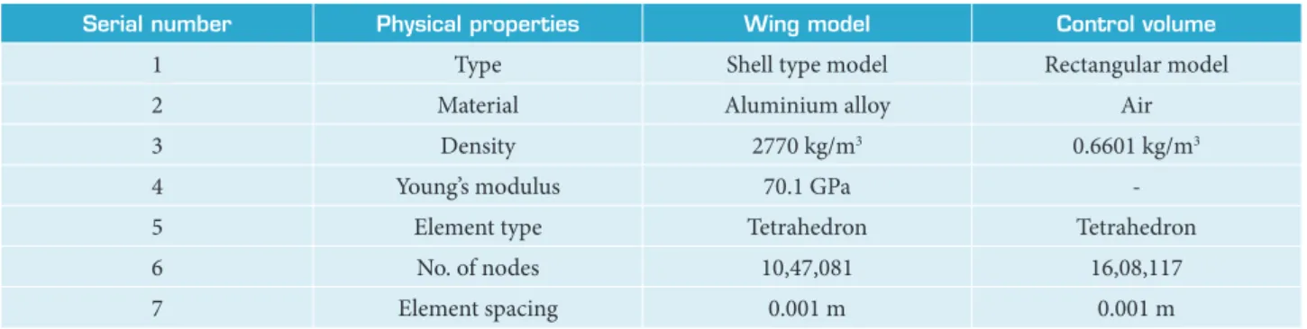
An elliptically generated boundary-fitted control volume that is wrapped around the scaled wing model is prepared for the flow field analysis with the following dimensions: height = 0.2 m, width = 1.0 m and spanwise extrusion = 2.5 m. The wing model is then subtracted from the control volume and the total volume of the wing model is immersed inside the control volume. However, the face connected at the root chord of the wing model is attached with a wall of the control volume. The control volume is assumed to be the boundary and the wing model is named as a surface. The physical properties of the wing model together with the control volume are listed in Table 1.
Figure 1. Doubly tapered wing model with control volume.
Serial number Physical properties Wing model Control volume
1 Type Shell type model Rectangular model
2 Material Aluminium alloy Air
3 Density 2770 kg/m3 0.6601 kg/m3
4 Young’s modulus 70.1 GPa
-5 Element type Tetrahedron Tetrahedron
6 No. of nodes 10,47,081 16,08,117
7 Element spacing 0.001 m 0.001 m
Table 1. Physical properties of the wing and control volume.
GRID GENERATION AND BOUNDARY CONDITION
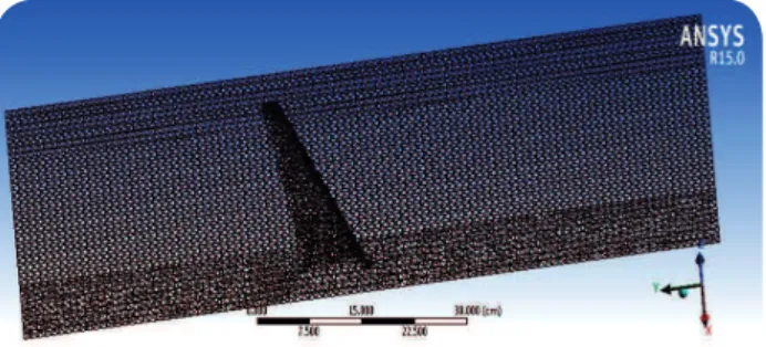
as surrounding walls. Th e upper and lower faces of the wing model are taken as fl uid-solid interfaces and the fl ow fi eld around the wing model is obviously turbulence in nature. Th e Spallart-Allmaras (SA) viscous model is used for the turbulence modelling process and the y+ value on the intermediate grid is maintained as 1 < y + < 30. Th e 1-equation model is applied for the turbulent fl ow analysis with density based 3-D implicit formulation (Barbarino et al. 2011). Th e eff ects of turbulence modelling are studied separately by comparing the SA model analysis results with k-epsilon model results. Th e fl ow is also assumed to be steady, and viscous (Sutherland) in nature.
Figure 2. Meshed view of the wing model with control volume.
object name Mesh
State Solved
defaults
Physics preference CFD
Solver preference Fluent
Sizing
Use advanced size function On: proximity and curvature
Relevance center Fine
Initial size seed Active assembly
Smoothing High
Transition Fast
Curvature normal angle Default (18.0°) Num cells across gap Default (3)
Proximity min size Default (1.5073e-002 cm)
Max face size 0.1 cm
Max size 0.1 cm
Growth rate Default (1.850)
Minimum edge length 0.23777 cm
infl ation
Use automatic infl ation None
Infl ation option Smooth transition
Transition ratio 0.272
Maximum layers 5
Growth rate 1.2
Infl ation algorithm Pre
View advanced options No
Patch conforming options
Triangle surface mesher Program controlled defeaturing
Pinch tolerance Default (1.3566e-002 cm)
Generate pinch on refresh No
The numerical values of the boundary condition are assumed as follows: the inlet/outlet gauge pressure is 21.73 kPa, Mach number = 0.85, Re = 8.4 × 10⁵. The density and temperature values are assigned according to the ISA conditions at 11 km altitude. In the course of FSI analysis, the pressure loads computed through flow analysis will be transferred to the structural module and then the deformations and stresses are computed. Here, the CFD module alone presented for observing the Cpdistributions in the morphing process before transferring the variables to the structural domain. If the flow variables are transferred to the structural domain then it becomes a computational aeroelastic investigation that captures the flow-induced stresses and vibration characteristics. The structural behaviour under various pressure loads at different AoA is not included herewith because of the scope of present article.
WING SWEEP MORPHING ANALYSIS
The one face of doubly tapered wing model which is attached to a side of the control volume face is assumed to be a fixed support in the flow analysis. The imported pressure load from the fluid flow solver is directly applied on the fluid-solid interfaces of the geometry. Earlier, Vortex Panel Method (VPM) and Conformal Mapping techniques were used to compute the pressure loads caused by various aerodynamic shapes theoretically (Pettit et al. 2001). Spalart Allmaras (SA) viscous model is chosen for the viscous flow analysis with the prescribed inlet and outlet boundary conditions. The drag convergence criterion is set about 0.0001 before initializing the iterative process and the number of iterations is fixed at 1000 to obtain the Coefficient of Drag (CD) convergence history. Here, Cartesian coordinate system is used with the direction specification method and solution initialisation of reference frame is set to be relative to cell zone (Liew et al. 2003). Residual monitor convergence is set for continuity, energy, and X, Y, Z components of velocities respectively.
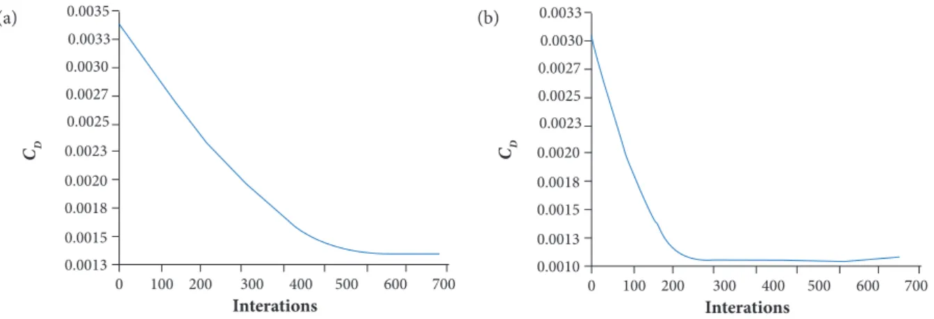
Figure 3.CD convergence plots for 28° (a) and 32° (b) sweep angles.
The flow analysis is done in the FLUENT solver for the doubly tapered wing at various degrees of wing sweep angle morphing at static conditions for 0° AoA. Initially, the Coefficient of lift (CL) and CD convergence trends are observed to evaluate the requirements such as grid spacing, grid independency and skewness. The unstructured surface grid with the number of nodes specified in Table 1 offers the solution convergence with sufficient accuracy over the sweep angles from 25° to 32°. As an example, among the 8 sweep angle magnitudes, two indicative CD convergence trends are presented in Fig. 3. The generic form of CD curve has a greater importance, and it is essentially linear for most of the practical range of the iterations. The solution is fully converged and the value of CD decreases at higher Λc/4 . During the initial simulation with smooth mesh transition module, the residual error convergence is obtained about 10-4 or below, and the points are steady and imbalance is kept below 1%. The mesh independency study is done at four mesh refinement levels (x, x/4, x/2, 2x) to ensure the consistency of the solution against the mesh quality. The solutions corresponding to x/2 refinement level is found to be satisfactory and further the results are independent of grid size.
0 100
0.0013 0.0015 0.0018 0.0020 0.0023 0.0025 0.0027 0.0030 0.0033 0.0035
200 300
Interations CD
400 500 600 700 0 100
0.0010 0.0013 0.0015 0.0018 0.0020 0.0023 0.0025 0.0027 0.0030 0.0033
200 300
Interations CD
400 500 600 700
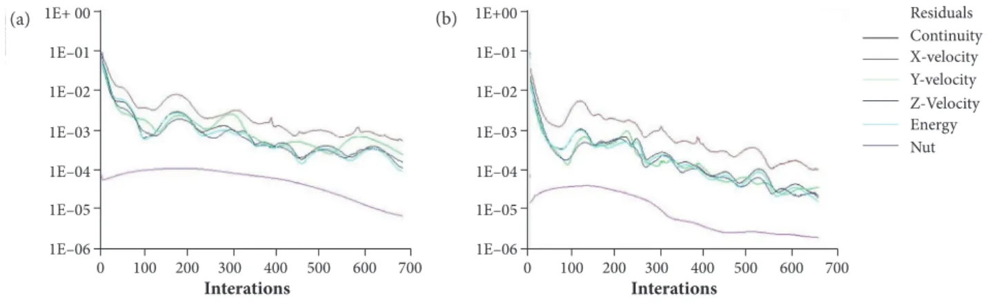
The results obtained for the variation of CD with iterations at different wing sweep angles (Λc/4 ) are analysed to validate the convergence properties. From the drag curve, it is observed that the incremental Λc/4 reduces the CD magnitude significantly without affecting the lateral stability of the wing configuration (Rose and Jinu 2015). The CD magnitude corresponding to Λc/4= 28° is about 0.00135 and for Λc/4= 32°it is only about 0.0011. Similar trends have also been observed for the CL convergence and it is not discussed at this point, since the article is focused on the drag reduction near Mcr through morphing strategies. The solution residuals are also observed at various Λc/4 and the residual plots corresponding to the two cases (Λc/4 = 28°and Λc/4= 32°) are presented in Fig. 4. In the sweep morphing analysis, the difference between the iterated value and the exact solution (Residuals) is in the range of 10-3 to 10-4 (Shili et al. 2008).
At lower sweep angles Λc/4 ≤ 25°, when air molecules within the boundary layer do not have adequate energy to reach the trailing edge of the airfoil and tends to move away from the surface by creating a wake region. As the AR begins to decrease, the flow separation is delayed significantly to overcome the adverse pressure gradient particularly in the high subsonic Mach number range. A novel methodology established at the NASA Langley Research Centre (NLRC) to resolve the wing spanwise lift distribution is to shift the wing pivot outside of the fuselage. However, outboard pivot concept is preferable only at the high Λc/4values for the variable sweep airplane wings (Ozgen et al. 2010). In addition to this, variable sweep wings pose serious problems such as stability and handling issues in the course of other missions except cruising flight at high AoA.
MACH NUMBER AND PRESSURES AFTER WING SWEEP MORPHING
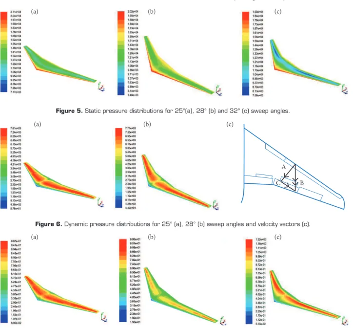
Conventionally, reducing the airfoil thickness ratio is the only mechanism to increase the Mcr at high subsonic speeds and later it was achieved through swept back wings. Mcr of an unswept wing (Mcr , Λ = 0) is fully based on the local airfoil thickness and oncoming free stream velocity components. Nevertheless, Mcr and pressure distributions over a swept wing (Mcr , Λ) depends on the velocity component perpendicular to the Leading Edge (LE) (Abdulrahim et al. 2004). As the sweep angle increases, the chord wise resultant velocity component also increases higher than the velocity vector perpendicular to the wing LE. Hence, static pressure drop occurs according to the law of conservation with respect to the incremental sweep angles. The magnitudes of static pressure computed through the flow analysis at three different sweep positions (25°, 28° and 32°) are presented in Fig. 5. The application of sweep morphing technology in the commercial airplanes is not still employed because of the mechanical complications associated with heavy structures (Icardi and Ferrero 2009). Hence, the inboard and outboard pivot concepts can be utilized to attain the maximum benefits of sweep morphing at an affordable cost with the current technology. The contours of static pressure distribution for various degrees of wing sweep angle of the doubly tapered wing design have confirmed static pressure drop at higher Λc/4 values. The pressure contours shown in Fig. 5 depicts the pressure drop in the mid-chord region because of the velocity vector normal to the LE is less than the chord wise resultant. In the same fashion, the dynamic pressure magnitude that results from the fluid motion is exactly opposite to the static pressure distribution and it is highlighted in Fig. 6.
Figure 4. Residuals plots for 28° (a) and 32° (b) sweep angles. 0 100
1E+00
1E–01
Residuals Continuity X-velocity Y-velocity Z-Velocity Energy Nut 1E–02
1E–03
1E–04
1E–05
1E–06
200 300
Interations
400 500 600 700 0 100
1E+ 00
1E–01
1E–02
1E–03
1E–04
1E–05
1E–06
200 300
Interations
400 500 600 700
As an example, dynamic pressures corresponding to 25°and 28° sweep angles only mentioned at this point as an indicative purpose. When Λc/4 increases, AC becomes shorter than AB and sweep morphing helps to increase the sonic boundary by increasing the airspeed. The maximum value of static pressure is observed at LE of the wing and the dynamic pressure is least possible at the LE as expected. Since the dynamic pressure is a function of Mach number and static pressure according to the expression q = 1/2γps M2
∞, the velocity component AB increases at higher Λc/4 values at 0° AoA. As the wing is reactive only to the component perpendicular to the LE, it determines the overall pressure and Mach number distributions in the process of sweep morphing. The onset of peak compressibility effects can be reduced through this morphing strategy with outboard pivot mechanism at the critical conditions of high speed flows (Elzey et al. 2005). The Mach number distribution at different Λc/4(25°, 28° and 32°) is displayed in Fig. 7 and shows the contribution of velocity component AB in the Mcr , Λ properties. Besides, the Mach contours highlight the maximum permissible airspeed at various sweep angles before the chord wise component become sonic. In brief, if the velocity vector AB increases, then the vector AC decreases, and vice versa. The reduction in vector AC in turn offers the higher Mcr , Λ at the given Mach number.
Figure 5. Static pressure distributions for 25°(a), 28° (b) and 32° (c) sweep angles.
Figure 6. Dynamic pressure distributions for 25° (a), 28° (b) sweep angles and velocity vectors (c).
Figure 7. Mach number distributions for 25°(a), 28° (b) and 32° (c) sweep angles. A
B C (a)
(a) (a)
(b)
(b) (b)
(c)
RESULTS AND DISCUSSION
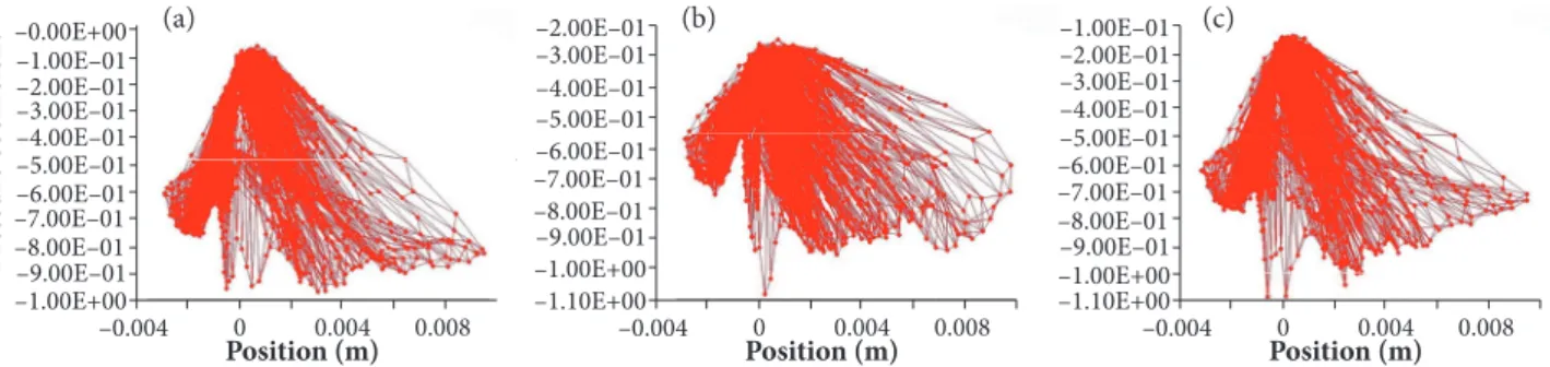
The Cp is inversely proportional to the pressure that results from the fluid motion, i.e., dynamic pressure. Hence, in the sweep morphing analysis it is observed that the magnitude of Cp continually decreases at higher sweep angles that reduce the overall induced drag near the sonic speeds. The Cp distribution versusx/c positions at various sweep angles is displayed in Fig. 8 with the relative pressure throughout the surface of doubly tapered wing. Here, every point in the chord wise location of the wing has its own unique Cpmagnitude conferring to the characteristics of the flow field.
–0.004 –1.10E+00 –1.00E+00 –9.00E–01 –8.00E–01 –7.00E–01 –6.00E–01 –5.00E–01 –4.00E–01 –3.00E–01 –2.00E–01 –1.00E–01 0.004 0.008 Position (m) 0 –0.004 –1.10E+00 –1.00E+00 –9.00E–01 –8.00E–01 –7.00E–01 –6.00E–01 –5.00E–01 –4.00E–01 –3.00E–01 –2.00E–01 0.004 0.008 Position (m) 0 –0.004 –1.00E+00 –9.00E–01 –8.00E–01 –7.00E–01 –6.00E–01 –5.00E–01 –4.00E–01 –3.00E–01 –2.00E–01 0.004 0.008 Position (m) P ress ur e c o effi ci en t 0 –1.00E–01 –0.00E+00
Figure 8.Cp distribution vs.x/c positions at 25° (a), 28° (b) and 32° (c) sweep angles.
The reduction in Cp that is obtained at high Mach numbers through the full scale sweep morphing process helps to minimize the occurrence of wave drag (Vos et al. 2007). Sweeping reduces the quantity of air flowing parallel to the chord line and it influences the overall lift produced by the wing though it is not a serious concern at high speeds. However, the airplanes equipped with swept wings are usually having the extended flaps to counter the loss of lift through wing sweep. Hence, wing chord morphing is another mechanism to customize an airplane’s Mcr characteristics particularly for the large-sized airplanes with increased speed capabilities. Instead of changing the local thickness of the airfoil or modifying the camber, the sweep morphing process itself helps to alter the entire Cp distribution over the airfoil to enhance the aerodynamic efficiency at high subsonic speeds.
Wing Chord MorPhing AnAlySiS
The wing chord morphing for the transport jets is still in the conceptual stage because of the complications associated with the actuator systems design, aerodynamic moments and weight penalties. Therefore, simplified novel methods are used by the researchers to overcome the aerodynamic and structural design problems sequentially. The proposed chord morphing strategy can be employed with the help of existing flap control systems and LE slats that are commonly exist in the modern airplanes (Heinze and Karpel 2006). The flap deflection also adjusts the CL drop that happens because of the wing sweeping without any major changes in the airplane AoA. The CFD flow analysis is done with the similar doubly tapered wing model (with NACA 63-209) for various chord dimensions at M = 0.85. The incremental Mean Aerodynamic Chord (MAC) is assumed for three different cases such as 2.5%C, 5%C, and 7.5%C at 0° AoA. Each chord dimension is obtained by increasing the MAC by 0.5% from the standard baseline wing dimensions.
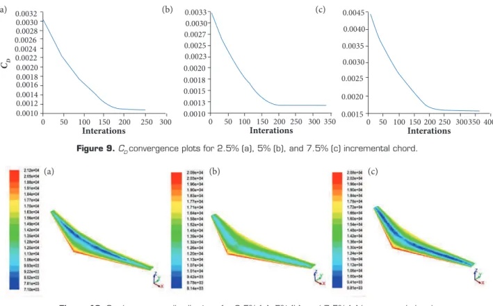
A refined tetrahedral grid is generated for both the control volume and the wing model based on the results obtained through the grid independency study as similar to Fig. 2. The operating conditions and convergence requirements also remain unchanged for the chord morphing analysis and the outlet boundary is set as pressure far-field. As an example, among the various chord dimensions, three indicative CD convergence trends are presented in Fig. 9. The wave drag contribution of the wing-fuselage combination and the aeroelastic characteristics of multisurface wing geometry are neglected at this point because it is not within the scope of this article. CD convergence plots show the incremental drag pertaining to the chord morphing process as expected and note that the Λc/4 value is maintained at 25°.
From the CD convergence plots, the value of CD increases gradually from 0.0011 to 0.0016 for various percentages of wing chord dimensions. Drag increments corresponding to each 0.5% MAC addition in the baseline configuration have been computed with
complete solution convergence. Solution residuals are monitored continuously and it is fully converged with the residuals in the range of 10-3 to 10-4 analogous to the sweep morphing case. Interestingly, the residual plots at higher chord values have shown a delay in the solution convergence for about few hundred iterations because of the compressibility effects at sonic speeds.
0 50 0.0010 0.0013 0.0015 0.0018 0.0020 0.0023 0.0025 0.0027 0.0030 0.0033
100 150
Interations CD
200 250 300 350 0 50 0.0015 0.0020 0.0025 0.0030 0.0035 0.0040 0.0045
100 150
Interations
200 250 300350 400 0 50
0.0010 0.0012 0.0014 0.0016 0.0020 0.0018 0.0022 0.0024 0.0026 0.0028 0.0030 0.0032
100 150
Interations
200 250 300
Figure 9.CD convergence plots for 2.5% (a), 5% (b), and 7.5% (c) incremental chord.
Figure 10. Static pressure distributions for 2.5% (a), 5% (b), and 7.5% (c) incremental chord.
MACH NUMBER AND PRESSURES AFTER WING CHORD MORPHING
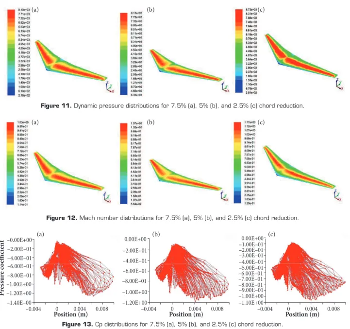
The local static pressure becomes less than the ambient pressure due to the compressibility effects and velocity somewhere on the aerofoil exceeds the free stream velocity. As it is known, according to the ISA conditions, the ambient static pressure at 11 km altitude is about 2.2616 × 10⁴ Pa. The static pressures computed for various percentages of chord morphing analysis are highlighted in Fig. 10. As the Mach number exceeds from M = 0.7, the difference between ambient (Pa) and local static pressures (P) begins to diverge (i.e., P < Pa). Therefore, the incremental chord morphing attains the Mcr earlier than the baseline configuration. Alternatively, when the chord dimension is reduced through telescopic control surfaces (Barrett 2004), the dynamic pressure and relative velocity components increase as shown in Fig. 11.
The drop in overall CL caused by an effective increment or reduction in the chord dimension can be adjusted by flying at higher Mach numbers (Abbott and von Doenhoff 1959). Accelerating the airplane to high speeds with sweep morphing helps to reduce the acceleration of the chordwise component of airflow, thus flying with higher Mcr , Λ. Therefore, the chordwise component of velocity AC increases with incremental chord values and vice versa. On the other hand, the relative velocity component increases with the chord morphing process if it is done with the extensive/retractable trailing edge control surfaces. At present, highly slender airfoils are extensively used for the large airplanes cruising at high subsonic speeds up to M = 0.87. Since, dynamic pressure (q) is a function of Mach number, significant reduction of “q” helps to accelerate the relative velocity component AB over the wing surface as highlighted in Fig. 12.
Similarly, when the sonic condition is reached on the airfoil surface because of the chordwise component of velocity, the corresponding Cp is known as critical pressure coefficient (Cp cri) and it occurs at the point of maximum velocity.For airfoils with more than 12% thickness, Cp cri is attained when the subsonic M = 0.7. However, for the supercritical airfoils this limit can be extended (a)
(a)
(b)
(b)
(c)
up to M = 0.87 with different flow control techniques. The Cp distribution computed for various percentage chord dimensions through partially coupled FSI analysis (Rose et al. 2014) is displayed in Fig. 13. Though, Cp distribution is observed for each 0.5% chord reduction, merely the results related to few specific intervals are presented herewith to emphasize their behaviour at Mcr.
The Cp distributions at each 0.5% incremental chord have been revealed the advantage of telescopic trailing and leading edge controls in the wing chord morphing strategy. The results presented in Fig. 13 are consistent with the dynamic pressure distributions obtained in Fig. 11 in terms of magnitudes at different chordwise positions. From the two-way large scale morphing analysis, it is concluded that the wing sweeping is beneficial within a prescribed margin to delay the Mcr value for supercritical airfoils. Similarly, the chord morphing requires a reduced planform to achieve higher cruising speeds near the transonic regime. The Cp distributions obtained at various percentage chord reductions can also be utilized to optimize the wing divergence characteristics at high speeds. However, a detailed adaptive grid clustering algorithm or/and a deforming mesh strategy is required for the full scale chord morphing analysis because of the rapid changes in the physical flow properties.
Figure 11. Dynamic pressure distributions for 7.5% (a), 5% (b), and 2.5% (c) chord reduction.
Figure 12. Mach number distributions for 7.5% (a), 5% (b), and 2.5% (c) chord reduction.
–0.004 –1.10E+00 –1.00E+00 –9.00E–01 –8.00E–01 –7.00E–01 –6.00E–01 –5.00E–01 –4.00E–01 –3.00E–01 –2.00E–01 –1.00E–01 0.004 0.008 Position (m) 0 0.00E+00 –0.004 –1.20E+00 –1.00E+00 –8.00E–01 –6.00E–01 –4.00E–01 0.00E+00 0.004 0.008 Position (m) 0 –2.00E–01 –0.004 –1.40E–00 –1.20E+00 –1.00E+00 –8.00E–01 –6.00E–01 –4.00E–01 0.004 0.008 Position (m) P ress ur e c o e ffi ci e n t 0 –2.00E–01 –0.00E+00
CONCLUSIONS
The doubly tapered wing section designed with a supercritical airfoil is used for the two-way wing morphing analysis to optimize the Mcr at high subsonic speeds. The results obtained from the wing sweep and chord morphing analyses are compared with each other in terms of drag convergence, Mach numbers and Cpdistributions. Each degree of sweep angle from 25° to
32° is investigated at 0° AoA to evaluate the influence of chordwise and relative components of flow velocity in the Mcr. The complexities associated with the thickness and camber morphing is succeeded through this large scale sweep morphing with respect to the outboard pivot point. The net reduction in the overall CL produced by the two-way morphing process is balanced
through the additional speed envelope provided by the morphed wing configuration. In addition, the proposed methodology can be
used with existing actuator systems and mechanical linkages in the main wing, thus resulting in a weight advantage as compared with other techniques. From the 3-D CFD simulation results, the maximum and minimum Cp locations are clearly observed at
different chordwise locations to evaluate the influence of flow separation. The presented work can be optimized further with the
help of a fully coupled CFD solver simulation to attain the best combination of sweep and percentage chord for a given airplane wing without any compromise in the overall L/D ratio before the Mcr limits.
AUTHOR’S CONTRIBUTION
Conceptualization, Bruce Ralphin Rose J and Baby Usha S; Methodology, Bruce Ralphin Rose J and Bibal Benifa JV; Investigation,
Bruce Ralphin Rose J; Baby Usha S and Bibal Benifa JV; Writing – Original Draft, Bruce Ralphin Rose J and Baby Usha S; Writing – Review & Editing, Bruce Ralphin Rose J and Baby Usha S; Resources, Baby Usha S and Bibal Benifa JV; Supervision, Bruce Ralphin Rose J.
REFERENCES
Abbott IH, von Doenhoff AE (1959) Theory of wing sections. New York: Dover Publications.
Abdulrahim A, Garcia H, Lind R (2004) Flight characteristics of shaping the membrane wing of a micro air vehicle. Journal of Aircraft 42(1):131-137.
ANSys Fluent. C2017. [accessed 2017 May 21]. http://www.ansys.com/Products/Fluids/ANSYS-Fluent.
Barbarino S, Bilgen O, Ajaj RM, Friswell MI, Inman DJ (2011) A review of morphing aircraft. Journal of Intelligent Material Systems and Structures 22.
Barrett R (2004) Adaptive aero structures: the first decade of flight on uninhabited aerial vehicles. Smart Structures and Materials 2004: Industrial and Commercial Applications of Smart Structures Technologies. doi: 10.1117/12.536681
Béguin B, Breitsamter C (2014) Effects of membrane pre-stress on the aerodynamic characteristics of an elasto-flexible morphing wing. Aerospace Science and Technology 37:138-150. doi: 10.1016/j.ast.2014.05.005
Berton B (2006) Shape memory alloys application: trailing edge shape control. Multifunctional Structures/Integration of Sensors and Antennas Meeting Proceedings RTO-MP-AVT-141, Paper 13; Neuilly-sur-Seine, France: RTO. p. 13-1–13-16.
Chattopadyay NC, Jony B, Acharya A (2012) An analysis on wing morphing. Proceedings of the Global Engineering, Science and Technology Conference; Dhaka, Bangladesh.
Cooper JE (2006) Adaptive Stiffness Structures for Air Vehicle Drag Reduction. Multifunctional Structures/Integration of Sensors and Antennas, Meeting Proceedings RTO-MP-AVT-141, Paper 15; Neuilly-sur-Seine, France: RTO. p. 15-1–15-12.
Coutu C, Brailovski V, Terriault P (2010) Optimized design of an active extrados structure for an experimental morphing laminar wing. Aerospace Science and Technology 14:451-458. doi: 10.1016/j.ast.2010.01.009
Elzey DM, Sofla AYN, Wadley HNG (2005) A shape memory-based multifunctional structural actuator panel. International Journal of Solids Structures 42(7):1943-1955. doi: 10.1016/j.ijsolstr.2004.05.034
Icardi U, Ferrero L (2009) Preliminary study of an adaptive wing with shape memory alloy torsion actuators. Materials and Design 30(1):4200-4210. doi: 10.1016/j.matdes.2009.04.045
Liew KM, He XQ, Meguid SA (2004) Optimal shape control of functionally graded smart plates using genetic algorithms. Computational Mechanics 33(4):245-253. doi: 10.1007/s00466-003-0525-1
Neal III DA (2006) Design, development, and analysis of a morphing aircraft model for wind tunnel experimentation (M.S. Thesis). Blacksburg, Virginia: Virginia Polytechnic Institute and State University.
Ozgen S, Yaman Y, Sahin M, Seber G, Unlusoy L, Sakarya E, Insuyu T (2010) Morphing air vehicle concepts. Proceedings of the International Workshop on Unmanned Vehicles – UVW. p. 46-51.
Pettit GW, Robertshaw HH, Inman DJ (2001) Morphing wings for unmanned aircraft, Smart Materials Bulletin 11:7-12. Doi:10.1016/ s1471-3918(01)80076-9
Rose BR, Jinu GR (2015) Influence of aeroelastic control reversal problem in the airplane lateral stability modes. Proceedings of the Institution of Mechanical Engineers, Part G: Journal of Aerospace Engineering 229(3):517-533. doi: 10.1177/0954410014537241
Rose BR, Jinu GR, Manivel M (2014) Partly coupled fluid structure interaction analysis of an aircraft wing at subsonic speeds. International Journal of Mechanical & Mechatronics Engineering 14(3):22-29.
Schweiger J, Suleman A (2003) The European Research Project – Active Aeroelastic Structures, CEAS, Int Forum on Aeroelasticity and Structural Dynamics.
Shili L, Wenjie G, Shujun L (2008) Optimal design of compliant trailing edge for shape changing. Chinese Journal of Aeronautics 21(2):187-192. doi: 10.1016/s1000-9361(08)60024-2
Sofla AYN, Meguid SA, Tan KT, Yeo WK (2010) Shape morphing of aircraft wing: Status and challenges. Materials and Design 31:1284-1292. doi: 10.1016/j.matdes.2009.09.011
Supekar AH (2007) Design, analysis and development of a morphable wing structure for unmanned aerial vehicle performance augmentation (M.S. Thesis) Arlington: The University of Texas, 2007.