E
NERGY AND
E
NVIRONMENT
Volume 2, Issue 4, 2011 pp.723-738
Journal homepage: www.IJEE.IEEFoundation.org
Optimizations of a model external combustion engine for
maximum work output with generalized radiative heat
transfer law
Kang Ma
1,2, Lingen Chen
1, Fengrui Sun
11 College of Naval Architecture and Power, Naval University of Engineering, Wuhan 430033, P. R.
China.
2 First Proving Ground, Naval Test Base, Huludao 125001, P. R. China.
Abstract
The generalized radiative heat transfer law [
q
∝
∆
( )
T
n ] is introduced into a model external combustionengine with a movable piston, and effects of heat transfer laws on the optimizations of the engine for maximum work output are investigated in this paper. Numerical examples for the optimizations with
linear phenomenological (n= −1), Newton’s (n=1), square (n=2), cubic (n=3) and radiative (n=4)
heat transfer laws are provided, respectively, and the obtained results are compared with each other. The results show that work output and efficiency of the optimal fully cyclic operation and optimal semi-cyclic operation decrease with the increase of heat conductance, and the work output, compression ratio and efficiency of the optimal semi-cyclic operation are larger than those of optimal fully cyclic operation. Although all of the curves of volume versus time of the optimal fully cyclic operation and the
Euler-Lagrange (E−L) arcs of the optimal semi-cyclic operation are nearly sinusoidal and consist of three
stages with the five heat transfer laws, the curves with different heat transfer laws are different.
Copyright © 2011 International Energy and Environment Foundation - All rights reserved.
Keywords: Finite time thermodynamics; Generalized radiative heat transfer law; Maximum work output; External combustion engine.
1. Introduction
An important problem in Finite Time Thermodynamics (FTT) or Entropy Generation Minimization (EGM) [1-10] is how to deal with the time dependence of process variables and parameters, i.e., how the dynamics of a system evolve during a process. In this case, the process evolves along an undetermined path, but may be subject to some constraints and bounds such as initial and final conditions. In order to determine performance limits for such systems, one has to find the thermodynamic path which extremalizes a given performance measure, which leads to an optimal configuration problem. The optimal control theory or Euler-Lagrange formalism can be applied to solve such problem.
class of irreversible internal combustion engines [20] and adiabatic internal combustion engine [21-24]. In solving such problems, due to that the only controllable variable is the volume of the cylinder which can be adjusted by moving the piston, the aim of such problems is to determine the optimal piston motions for extremalizing a given performance measure. Once the optimal piston motions have been determined, there are in fact several ways of achieving these pathways of which we point out just two: one solution to transform the optimized paths is the use of an electrical coupling [3], another completely different mechanical way is applying a contoured plate to guide the piston on the desired path.
Besides the objects studied in Refs. [11-24], the irreversible expansion process of ideal gas inside a heated cylinder with a moveable piston is also a classic object in the analysis of the optimal piston
motions. Band et al. [25, 26] first established the model of the irreversible expansion process, and further
investigated the optimal configurations of the process for maximizing the work with Newton’s heat
transfer law [q∝ ∆( )T ]. The obtained results showed that the optimal expansion consists of, at most,
three stages. In addition, the optimal configurations of the expansion subject to eight different constraints, including constrained rate of change of volume, unconstrained final volume, constrained final energy and final volume, constrained final energy and unconstrained final volume, consideration of piston friction, consideration of piston mass, consideration of gas mass and unconstrained total time,
were discussed respectively. Band et al. [27] further applied the results obtained in Refs. [25, 26] to a
model external combustion engine with Newton’s heat transfer law, and found that the optimal motion of the engine contains fully cyclic operation and semi-cyclic operation, and once the initial steady-state temperature is ensured, the optimal motion is changed into the fully cyclic operation from the
semi-cyclic operation. Salamon et al. [28] and Aizenbud and Band [29] further investigated the optimal
configurations of the expansion process for maximizing power output [28] and the optimal configurations for maximizing work output with fixed power output [29] with Newton’s heat transfer
law. Aizenbud et al. [30] further applied the results obtained in Refs. [25, 26] to a model internal
combustion engine with Newton’s heat transfer law. In all of the investigations [11-30], the heat transfer between the working fluid in the cylinder and the environment obeys the Newton’s heat transfer law. Thus, such investigations can be expanded by introducing different heat transfer laws into the optimal
configurations problems, such as the linear phenomenological heat transfer law [ 1
( )
q∝ ∆T− ], the
radiative heat transfer law [ 4
( )
q∝ ∆T ], the generalized radiative heat transfer law [ ( n)
q∝ ∆T ], the
generalized convective heat transfer law [ ( )m
q∝ ∆T ], the complex generalized heat transfer law
[ ( ( n))m
q∝ ∆T ] and the convective-radiative heat transfer law [ 4
( )
q∝ ∆ + ∆T T ]. Effects of heat transfer law on the optimal piston motions for different engines has been investigated, including the Otto cycle engine [31, 32], the Diesel cycle engine [33, 34], the irreversible light-driven engine [35], the irreversible heat engine with distributed working fluid [36] and a class of irreversible internal combustion engines [37]. Different heat transfer laws has also been introduced into the optimal configurations problems of
the irreversible expansion process of ideal gas inside a heated cylinder with a moveable piston. Chen et
al.[38], Song et al.[39] and Chen et al.[40] determined the optimal expansion when the heat transfer
between the working fluid and the external heat bath obeys, respectively, the linear phenomenological [38], the generalized radiative [39] and convective-radiative [40] heat transfer laws. In Ref. [39], the first-order approximate analytical solutions about the Euler-Lagrange arcs were obtained by means of
Taylor series expansion with the square, cubic and radiative heat transfer laws when the total time tm is
very short. Ma et al. [41] repeated the investigations on the optimal configurations of expansion process
with the generalized radiative heat transfer law by means of elimination method, and derived the exact analytical solutions of the intermediate Euler-Lagrange arc with square and cubic heat transfer laws.
Song et al.[42] further introduced the linear phenomenological heat transfer law into the model external
combustion engine, and studied the effects of heat transfer laws on the optimal motion. Chen et al.[43]
applied the results obtained in Ref. [38] to the model internal combustion engine with the linear phenomenological heat transfer law.
In this paper, based on Refs. [26, 27, 41, 42], the generalized radiative heat transfer law [q∝ ∆(Tn)]
[44-49] is introduced into a model external combustion engine with a movable piston, and effects of heat transfer laws on the optimizations of the engine for maximum work output are investigated in this paper.
Numerical examples for the optimizations with linear phenomenological (n= −1), Newton’s (n=1),
square (n=2), cubic (n=3) and radiative (n=4) heat transfer laws are provided, respectively, and the
2. Optimal Solutions
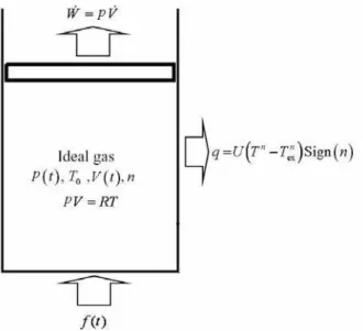
The model external combustion engine with a movable piston is shown in Figure 1. The gas inside the
cylinder is only 1 mol, and is coupled to an external heat bath at a constant temperature Tex. A heat
source heats the gas uniformly with the rate of output f t( ), which is an arbitrary given function of time.
The heat transfer between the gas and the external heat bath is assumed to obey the generalized radiative
heat transfer law [q∝ ∆(Tn)], where q is the heat flux across the cylinder walls with heat conductance
U , T is the gas temperature. As done in Refs. [25-30, 38-43], it is assumed that the wall conducts heat
very fast and all parts of the cylinder heat up regardless of the position of the piston. Therefore, the heat
conductance U of cylinder wall can be taken to be a constant. Furthermore, it is assumed that the inertia
of the gas and the piston is negligible and there is no friction associated with the movement of the piston.
Figure 1. Schematic diagram of the model: a mole of ideal gas inside a cylinder is pumped by a given heating function f t( ) and is coupled to heat bath
For the system, the following equation can be obtained by using the first law of thermodynamics
( ) ( ) ( ) [ n( ) exn] ( )
E t& = f t −W t& −U T t −T Sign n (1)
where E& is the rate of change of internal energy of the gas, W t&( ) is the power of expansion against the piston, and Sign n( ) is a sign function, Sign n( )=1 if n>0 and Sign n( )= −1 if n<0. One wishes to
maximize the power output, i.e. maximize the work output per cycle with fixed f t( ), initial volume V0
of the gas, final volume Vm of the gas, initial internal energy of the gas E0, and total time tm allowed for the cycle.
The results of Ref. [41] showed that the optimal control for the expansion of a heated working fluid with the generalized radiative heat transfer law consists of, at most, three stages: (1) an initial instantaneous
adiabat; (2) an intermediate Euler-Lagrange arc, i.e. E−L arc; and (3) a final instantaneous adiabat.
Stage (1) is the initial adiabat from V(0) to '
(0)
V at t=0. The equation is
/
' '
(0) (0)[ (0) / (0)] R CV
E =E V V − (2)
where '
(0)
E is the final value of internal energy of the initial instantaneous adiabat.
Stage (2) is the Euler-Lagrange arc (E−L arc) and proceeds from the initial '
(0)
V and '
(0)
E at t=0
until time t=tm. Based on Ref. [41], the E−L arc can be determined using the following equations:
( ) ( () )( )n+1( )( ) ( ) ( ) ( ) ( ) ( )Vn n+1( )( ) ( ) ( )
n 1 n
n n n n
V V
n 1 UE' 0 Sign n C E' 0
E t E t F t 0
n 1 UE' 0 Sign n C F 0 n 1 UE' 0 Sign n C F 0
+ − − − =
( )
( )
( )
( )
V( )
( )
( )
( )
n C R t V V 0F t U E t C Sign n
E t C
V t V' 0 exp dt
E' 0 R E t
− ⎧ ⎫
− ⎡ ⎤
⎡ ⎤ ⎪ ⎣ ⎦ ⎪
= ⎢ ⎥ ⎨ ⎬
⎢ ⎥ ⎪ ⎪
⎣ ⎦ ⎩
∫
⎭ (4)where CV is molar heat capacity, R is the universal gas constant, and
( )
( )
Sign( )
exnF t = f t + n UT .
The E−L arcs for different heat transfer laws are different, and the corresponding solving methods are
different as well. For the cases of n= −1, n=1, n=2 and n=3, the analytical solutions about the E−L
arcs can be derived by solving Eqs. (3) and (4); while n≥4, since the analytical solution of E t
( )
cannotbe derived by solving Eq. (3), the solution about the E−L arc should be determined by using the
numerical techniques.
Stage (3) is the final adiabat from V t( )m to Vm at t=tm
/
( )[ / ( )] R CV
m m m m
E =E t V V t − (5)
where V t( )m and E t( )m can be obtained from Equations of E−L arcs at time tm.
3. Applications to the optimization of the model external engine
Optimal configurations of expansion process of a heated working fluid in the piston cylinder for maximizing work output with the generalized radiative heat transfer law have been determined in Refs. [39, 41], and the obtained results can be further applied to the investigations of optimal configurations for maximizing power output, investigations of optimal configurations for maximizing work output with fixed power output, optimizations of the model external combustion engine and optimizations of the model internal combustion engine with the generalized radiative heat transfer law. Based on Refs. [27, 41, 42], optimal operations of a model external combustion engine for maximizing work output with fixed the total time tm and heating function f t( ) are investigated in this section.
According to Refs. [27, 42], optimal operation of the model external combustion engine contains fully cyclic operation and semi-cyclic operation. It is assumed that the engine is changed to fully cyclic
operation from time ti. The solution for the fully cyclic operation can be obtained from the equations of
E−L arc with the condition that at time t= +ti tm, V t( ) and E t( ) return to their initial values. Since
( )
F t is assumed to be periodic with period tm, the exponential of the right-hand side of Eq. (4) should
vanish at t= +ti tm, and then the initial value of internal energy at time ti for fully cyclic operation, E t( )i ,
can be obtained. The constraint E t( )i =E t(i +tm) reduces the number of degrees of freedom available in
controlling the system operation. As a result, the optimal fully cyclic operation contains no adiabats. At the very start of engine operation, the temperature of the working fluid equals to the external
temperature, Tex. It will therefore require a number of cycles (semi-cyclic operation) before the initial
temperature reaches the initial steady-state temperature for fully cyclic operation. In the semi-cyclic operation, only V t( )i =V t(i+tm) is satisfied, and the temperature of the working fluid is not periodic. The optimal semi-cyclic operation consists of three stages: (1) an initial instantaneous adiabat; (2) an
intermediate E−L arc; and (3) a final instantaneous adiabat.
The methods to determine the optimal final value of internal energy of the initial instantaneous adiabat, '(0)
E , for different heat transfer laws (different values of n) are different. For the cases of n= −1, n=1,
n=2 and n=3, the analytical solutions about the E−L arcs can be derived by solving Eq. (3). Then, as
done in Refs. [27, 42], the optimal staging problem for maximum expansion work W becomes a
one-dimensional optimization problem. To determine the optimal E'(0), taking the derivation of W with
respect to E'(0) and setting it equal to zero ( '
( )
dW dE 0 =0), one can get [41]
( )
[
]
{
( )}
( ) ( ) m t n V 0 m ' 'd U Sign n E t C dt dE
+ =0
dE 0 dE 0
⎡ ⎤ ⎣ ⎦
∫
(6)
While for the case of n≥4, since the analytical solution of E t
( )
cannot be derived by solving Eq. (3),the optimal E'(0) should be determined by using the numerical techniques.
Once the initial temperature (E t( ) /i CV) is ensured, the optimal motion is changed into the fully cyclic
(regardless of the form of the heating function). The cyclic nature of the solution forces the elimination of the adiabatic arcs.
The work output W per cycle in the time internal ( ,t ti i+tm) is
( )
( ) ( ) ( ) ( )
i m i m
i i
t t t t n
i i m n
t t
V
USign n
W F t dt E t E t t E t dt C
+ +
=
∫
+ − + −∫
(7)The irreversible efficiency of the process η is defined as
/ p
W E
η = (8)
where Ep is the energy pumped into the system, 0 ( )
m
t
f t dt
∫
.The optimal operations of the engine for different heat transfer laws are as following.
3.1 Optimal operation with n= −1 [42]
When n= −1, the heat transfer obeys linear phenomenological heat transfer law used in irreversible
thermodynamics [44].
Firstly, the analytical solution of optimal internal energy E t
( )
with respect to F t( )
and E t( )i can beobtained by substituting n= −1 into Eq. (3)
( )
[
2 ( )]
2 ( ) ( ) ( )
V i
V i i
UC E t E t
UC F t F t E t
=
− − (9)
Secondly, the exponential of the right-hand side Eq. (4) should vanish at t= +ti tm, yields the condition
2 1 2
( ) 2 / {[ i m ( ) / ] ( )}
i
t t
i V m i
t
E t = UC
∫
+ F t dt t −F t (10)There are two solutions of Eq. (10), a positive one and a minus one, and the positive one should be held.
Finally, the value of E'(0) for the optimal semi-cyclic operation can be determined using Eq. (6) by
means of numerical techniques.
Since the values of E t( )i for the optimal fully cyclic operation and E'(0) for the optimal semi-cyclic
operation are determined, the optimal fully cyclic operation and the optimal semi-cyclic operation can be determined using Eqs. (4) and (9).
3.2 Optimal operation with n=1 [27]
When n=1, the heat transfer obeys Newton’s heat transfer law.
Firstly, the analytical solution of optimal internal energy E t
( )
with respect to F t( )
and E t( )i can beobtained by substituting n=1 into Eq. (3)
( ) ( )[ ( ) / ( )]1 2
i i
E t =E t F t F t (11)
Secondly, the exponential of the right-hand side Eq. (4) should vanish at t= +ti tm. One has
1 2 1 2
( ) = ( ) i m ( )
i
t t
/ /
V
i i t
m
C
E t F t F t dt
URt
+
∫
(12)Finally, the value of E'(0) for the optimal semi-cyclic operation can be determined using Eq. (6) by
means of numerical techniques.
Since the values of E t( )i for the optimal fully cyclic operation and E'(0) for the optimal semi-cyclic
operation are determined, the optimal fully cyclic operation and the optimal semi-cyclic operation can be determined using Eq. (4) and Eq. (11).
3.3 Optimal operation with n=2
When n=2, the heat transfer is applicable to radiation propagated along a one-dimensional transmission
line, and the heat transfer coefficient in this case is equal to 2 2
/(6 )
k h
π , where h is the Planck’s constant
Firstly, the analytical solution of optimal internal energy E t
( )
with respect to F t( )
and E t( )i can beobtained by substituting n=2 into Eq. (3)
( )
2 1 2 23 12 2 1 34 16
AU A U B B
E t = + + (13)
where
3 2 2
1 ( ) /i ( )i V ( )i
A =E t ⎡⎣UE t +C F t ⎤⎦ (14)
2 3 3 2 4 2 4 2 3 1 3
1 [27 1 V ( ) 2 1 3 3 27 1 V ( ) 4 1 V ( ) ]
B = A C F t + A U + A C F t + A C U F t (15)
Secondly, the exponential of the right-hand side Eq. (4) should vanish at t= +ti tm. One has
( )
( )
( )
2i m
i
t t V
t
F t U E t C
dt=0 E t
+ − ⎡⎣ ⎤⎦
∫
(16)The value of E t( )i for the optimal fully cyclic operation can be determined using Eq. (16) by means of
numerical techniques.
Finally, the value of E'(0) for the optimal semi-cyclic operation can be determined using Eq. (6) by
means of numerical techniques. Since the values of E t( )i for the optimal fully cyclic operation and E'(0)
for the optimal semi-cyclic operation are determined, the optimal fully cyclic operation and the optimal semi-cyclic operation can be determined using Eq. (4) and Eq. (13).
3.4 Optimal operation with n=3
When n=3, the heat transfer is applicable to radiation propagated along a two-dimensional surface [44].
Firstly, the analytical solution of optimal internal energy E t
( )
with respect to F t( )
and E t( )i can beobtained by substituting n=3 into Eq. (3)
3 3
2 2 2 2 1 3 1 2 2 2 2 2 2 1 3
2 1 3 2 1 3
2 2
3 3
1 2 2
2 2 3 1 3 1 3 1 2
2 2 2
2 ( ) 2 2 ( ) 2
1 1
( ) [ ( ) ] [2 ( )
2 ( 3 4 ) 9 2 2 ( 3 4 ) 9
2
]
[ 2 ( ) ( 3 4 ) ( 2 9 ) ]
V V
V
A C F t B A U A C F t B
E t A U A U
B B
A U
A U AC F t B B
= − + + + + − +
− +
(17)
where
4
2 3 3
( )
2 ( ) ( )
i
i V i
E t A
UE t C F t =
+ (18)
3 3 2 3 9 3 6 6 4 2
2 9 2 V ( ) 3 16 2 V ( ) 27 2 V ( )
B = − A C U F t + A C F t + A C U F t (19)
Secondly, the exponential of the right-hand side Eq. (4) should vanish at t= +ti tm. One has
( )
( )
( )
3i m
i
t t V
t
F t U E t C
dt=0 E t
+ − ⎡⎣ ⎤⎦
∫
(20)The value of E t( )i for the optimal fully cyclic operation can be determined using Eq. (20) by means of
numerical techniques.
Finally, the value of E'(0) for the optimal semi-cyclic operation can be determined using Eq. (6) by
means of numerical techniques.
Since the values of E t( )i for the optimal fully cyclic operation and E'(0) for the optimal semi-cyclic
operation are determined, the optimal fully cyclic operation and the optimal semi-cyclic operation can be determined using Eq. (4) and Eq. (17).
3.5 Optimal operation with n=4
When n=4, the heat transfer obeys radiative heat transfer law if all the bodies are black, and the heat
5 4 5
5 4
4 4 4 4
3 ( ) ( )
( ) ( ) ( ) 0
3 ( ) ( ) 3 ( ) ( )
i V i
i V i i V i
UE t C E t
E t E t F t
UE t C F t UE t C F t
− − =
+ + (21)
The analytical solution of E t
( )
with respect to F t( )
and E t( )i cannot be obtained because Eq. (21)cannot be solved directly.
Secondly, the exponential of the right-hand side Eq. (4) should vanish at t= +ti tm. One has
( )
( )
( )
4i m
i
t t V
t
F t U E t C
dt=0 E t
+ − ⎡⎣ ⎤⎦
∫
(22)The value of E t( )i for the optimal fully cyclic operation can be determined using Eqs. (21)-(22) by
means of numerical techniques.
Finally, because the analytical solution of E t
( )
cannot be obtained, the value of E' 0( ) cannot bedetermined using the equation dW d '(0)E =0, which is used for the cases of n= −1, n=1, n=2 and
n=3. In order to find the optimal value of E' 0
( )
, the method of exhaustion is adopted. All possiblevalues of E' 0
( )
are chosen to calculate the corresponding values of objective function W . Then, theoptimal value of E' 0
( )
to maximize the objective function can be determined.Since the values of E t( )i for the optimal fully cyclic operation and E'(0) for the optimal semi-cyclic
operation are determined, the optimal fully cyclic operation and the optimal semi-cyclic operation can be determined using Eq. (4) and Eq. (21).
4. Numerical examples
Now, numerical examples for the optimal piston motion of a model external combustion engine for maximizing work output with the generalized radiative heat transfer law are provided. In the calculations,
3 3
(0) m 1 10
V =V = × − m , E(0)=3780J, Tex=300K, CV =3 / 2R , tm =2s and 60
( ) [sin( )]
f t =A ωt , where
204720 / s
A= J and ω=2 / 4π rad/ s are set.
4.1 Numerical example for n= −1
Table 1 lists the values of the state variables, the maximum work output W and the corresponding
efficiency η for the optimal fully cyclic operation and the optimal semi-cyclic operation. It can be seen
from Table 1 that with the increase of heat conductance U , the energy leaking into the bath from the gas
increases, so both the maximum work output W and the corresponding efficiency η for two optimal
operations decrease progressively. The compression ratio γ , work output W and corresponding
efficiency η for the optimal semi-cyclic operation are larger than those for the optimal fully cyclic
operation. This is because that in the optimal semi-cyclic operation, only V t( )i =V t(i+tm) is satisfied, while in the optimal fully cyclic operation, both V t( )i =V t(i+tm) and E t( )i =E t(i+tm) are satisfied. This means that in the optimal semi-cyclic operation, relaxing system constraint and weakening the
assumptions on system operations, yields larger work output W and corresponding efficiency η;
whereas in the optimal fully cyclic operation, adding constraints and tightening the assumptions, yields
smaller work output W and corresponding efficiency η.
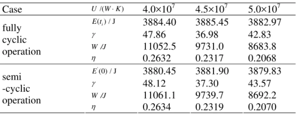
Table 1. Parameters versus U for case of n=-1
Case U /(W K⋅ ) 4.0×10⁷ 4.5×10⁷ 5.0×10⁷
( ) / Ji
E t 3884.40 3885.45 3882.97
γ 47.86 36.98 42.83
W /J 11052.5 9731.0 8683.8 fully
cyclic
operation η
0.2632 0.2317 0.2068
'
(0) / J
E 3880.45 3881.90 3879.83
γ 48.12 37.30 43.57
W /J 11061.1 9739.7 8692.2
semi -cyclic
operation η
Figures 2 and 3 show, respectively, optimal volume versus time of the optimal fully cyclic operation and the optimal semi-cyclic operation. Figures 4 and 5 show, respectively, optimal cycles of the optimal fully cyclic operation and the optimal semi-cyclic operation.
It can be seen from Figure 2 that piston motion for the optimal fully cyclic operation is nearly sinusoidal, and consists of three stages: (1) an initial compression process; (2) an intermediate expansion process; and (3) final compression process. The time spent on the intermediate expansion process is
approximately 0.5s, which is shorter than those on the two compression processes. In addition, with the
increase of heat conductance U, the maximum volume of the working fluid during the expansion
process increases progressively. This is because that with the increase of heat conductance U , the energy
leaking into the bath from the gas increases, the ability of heat-work conversion of the engine is weakened. Therefore, to cover the decrement of the ability of heat-work conversion, the maximum volume of the working fluid during the expansion process should increase.
Figure 2. Optimal volume versus time of the
optimal fully cyclic operation when n=-1
Figure 3. Optimal volume versus time of the
optimal semi-cyclic operation when n=-1
Figure 4. Optimal cycle of the optimal fully cyclic
operation when n=-1
Figure 5. Optimal cycle of the optimal semi-cyclic
operation when n=-1
It can be seen from Figure 3 that the optimal semi-cyclic operation consists of three stages: (1) an initial
instantaneous adiabat; (2) an intermediate E−L arc; and (3) a final instantaneous adiabat. The piston
motion during the intermediate E−L arc for the optimal semi-cyclic operation is similar with that for
optimal fully cyclic operation. In addition, with the increase of heat conductance U , the maximum
volume of the working fluid during E−L arc increases progressively.
It can be seen from Figures 4 and 5 that with the increase of heat conductance U , the energy leaking into
the bath from the gas increases, so the maximum internal energy decrease progressively. In addition, in the semi-cyclic operation, only V t( )i =V t(i+tm) is satisfied, and the temperature of the working fluid is
not periodic. Once the initial steady-state temperature (E t( ) /i CV ) is ensured, the optimal motion is
4.2 Numerical example for n=1
Table 2 lists the values of the state variables, the maximum work output W and the corresponding
efficiency η for the optimal fully cyclic operation and the optimal semi-cyclic operation. It can be seen
that with the increase of heat conductance U , the maximum work output W and the corresponding
efficiency η for two optimal operations decrease progressively. In addition, the compression ratio γ,
work output W and corresponding efficiency η for the optimal semi-cyclic operation are larger than
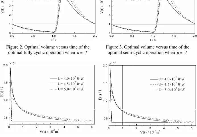
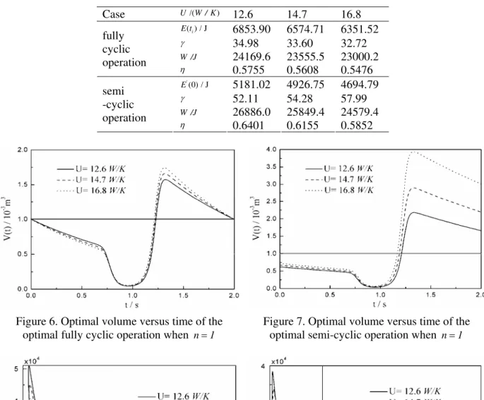
those for the optimal fully cyclic operation. Figures 6 and 7 show, respectively, optimal volume versus time of the optimal fully cyclic operation and the optimal semi-cyclic operation. Figures 8 and 9 show, respectively, optimal cycles of the optimal fully cyclic operation and the optimal semi-cyclic operation.
The similar characteristics as those for the case of n=-1 can be seen from Figures 6-9.
Table 2. Parameters versus U for case of n=1
Case U /(W / K) 12.6 14.7 16.8
( ) / Ji
E t 6853.90 6574.71 6351.52
γ 34.98 33.60 32.72
W /J 24169.6 23555.5 23000.2 fully
cyclic
operation η
0.5755 0.5608 0.5476
'
(0) / J
E 5181.02 4926.75 4694.79
γ 52.11 54.28 57.99
W /J 26886.0 25849.4 24579.4
semi -cyclic operation
η 0.6401 0.6155 0.5852
Figure 6. Optimal volume versus time of the
optimal fully cyclic operation when n=1
Figure 7. Optimal volume versus time of the
optimal semi-cyclic operation when n=1
Figure 8. Optimal cycle of the optimal fully cyclic
operation when n=1
Figure 9. Optimal cycle of the optimal semi-cyclic
4.3 Numerical example for n=2
Table 3 lists the values of the state variables, the maximum work output W and the corresponding
efficiency η for the optimal fully cyclic operation and the optimal semi-cyclic operation. It can be seen
that with the increase of heat conductance U , the maximum work output W and the corresponding
efficiency η for two optimal operations decrease progressively. In addition, the compression ratio γ,
work output W and corresponding efficiency η for the optimal semi-cyclic operation are larger than
those for the optimal fully cyclic operation.
Figures 10 and 11 show, respectively, optimal volume versus time of the optimal fully cyclic operation and the optimal semi-cyclic operation. Figures 12 and 13 show, respectively, optimal cycles of the optimal fully cyclic operation and the optimal semi-cyclic operation. The similar characteristics as those
for the case of n=-1 can be seen from Figures 10-13.
Table 3. Parameters versus U for case of n=2
Case 2
/( )
U W / K 0.04 0.05 0.06
( ) / Ji
E t 6118.66 5784.51 5543.27
γ 24.55 28.26 32.00
W /J 14228.1 13734.9 13291.3 fully
cyclic
operation η
0.3388 0.3270 0.3165
'(0) / J
E 5493.19 5321.19 5183.24
γ 39.39 42.79 46.30
W /J 16085.2 15185.6 14464.5
semi -cyclic
operation η
0.3830 0.3616 0.3444
Figure 10. Optimal volume versus time of the
optimal fully cyclic operation when n=2
Figure 11. Optimal volume versus time of the
optimal semi-cyclic operation when n=2
Figure 12. Optimal cycle of the optimal fully
cyclic operation when n=2
Figure 13. Optimal cycle of the optimal semi-cyclic
4.4 Numerical example for n=3
Table 4 lists the values of the state variables, the maximum work output W and the corresponding
efficiency η for the optimal fully cyclic operation and the optimal semi-cyclic operation. It can be seen
that with the increase of heat conductance U , the maximum work output W and the corresponding
efficiency η for two optimal operations decrease progressively. In addition, the compression ratio γ,
work output W and corresponding efficiency η for the optimal semi-cyclic operation are larger than
those for the optimal fully cyclic operation. Figures 14 and 15 show, respectively, optimal volume versus time of the optimal fully cyclic operation and the optimal semi-cyclic operation. Figures 16 and 17 show, respectively, optimal cycles of the optimal fully cyclic operation and the optimal semi-cyclic operation.
The similar characteristics as those for the case of n=-1 can be seen from Figures 14-17.
Table 4. Parameters versus U for case of n=3
Case 3
/( )
U W / K 2.0×10⁻⁴ 2.5×10⁻⁴ 3.0×10⁻⁴
( ) / Ji
E t 5050.35 4862.91 4726.51
γ 57.63 70.08 82.4395
W /J 9230.6 8839.3 8492.15 fully
cyclic
operation η
0.2198 0.2105 0.2022
'
(0) / J
E 4911.15 4760.40 4647.22
γ 74.91 87.67 100.24
W /J 9853.4 9285.6 8868.0 semi
-cyclic
operation η
0.2346 0.2211 0.2111
Figure 14. Optimal volume versus time of the
optimal fully cyclic operation when n=3
Figure 15. Optimal volume versus time of the
optimal semi-cyclic operation when n=3
Figure 16. Optimal cycle of the optimal fully
cyclic operation when n=3
Figure 17. Optimal cycle of the optimal semi-cyclic
4.5 Numerical example for n=4
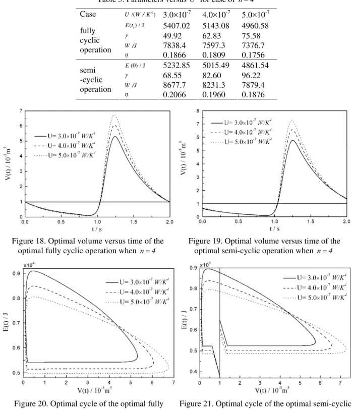
Table 5 lists the values of the state variables, the maximum work output W and the corresponding
efficiency η for the optimal fully cyclic operation and the optimal semi-cyclic operation. It can be seen
that with the increase of heat conductance U , the maximum work output W and the corresponding
efficiency η for two optimal operations decrease progressively. In addition, the compression ratio γ,
work output W and corresponding efficiency η for the optimal semi-cyclic operation are larger than
those for the optimal fully cyclic operation. Figures 18 and 19 show, respectively, optimal volume versus time of the optimal fully cyclic operation and the optimal semi-cyclic operation. Figures 20 and 21 show, respectively, optimal cycles of the optimal fully cyclic operation and the optimal semi-cyclic operation.
The similar characteristics as those for the case of n=-1 can be seen from Figures 18-21.
Table 5. Parameters versus U for case of n=4
Case 4
/( )
U W / K 3.0×10⁻⁷ 4.0×10⁻⁷ 5.0×10⁻⁷
( ) / Ji
E t 5407.02 5143.08 4960.58
γ 49.92 62.83 75.58
W /J 7838.4 7597.3 7376.7 fully
cyclic
operation η
0.1866 0.1809 0.1756
'
(0) / J
E 5232.85 5015.49 4861.54
γ 68.55 82.60 96.22
W /J 8677.7 8231.3 7879.4 semi
-cyclic
operation η
0.2066 0.1960 0.1876
Figure 18. Optimal volume versus time of the
optimal fully cyclic operation when n=4
Figure 19. Optimal volume versus time of the
optimal semi-cyclic operation when n=4
Figure 20. Optimal cycle of the optimal fully
cyclic operation when n=4
Figure 21. Optimal cycle of the optimal semi-cyclic
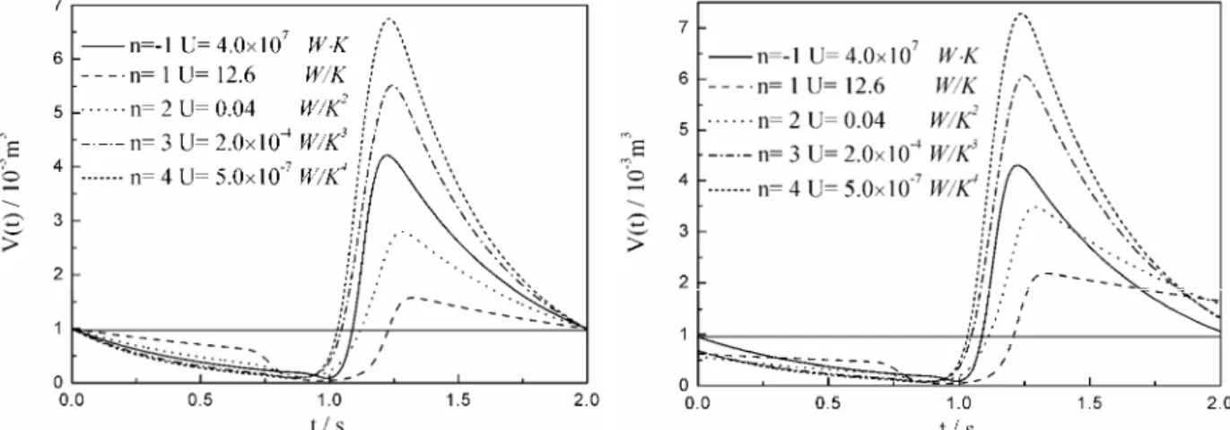
4.6 Comparisons between optimal operations with special heat transfer laws
Figures 22 and 23 show, respectively, optimal volume versus time of the optimal fully cyclic operation and the optimal semi-cyclic operation for five special heat transfer laws. Figures 24 and 25 show, respectively, optimal cycles of the optimal fully cyclic operation and the optimal semi-cyclic operation for five special heat transfer laws. It can be seen from Figures 22-25 that although all of the curves of
volume versus time of the optimal fully cyclic operation and the E−L arcs of the optimal semi-cyclic
operation are nearly sinusoidal and consist of three stages with the five heat transfer laws, the curves with different heat transfer laws are different. The differences for the optimal operations with different
heat transfer laws are as follows: (1) in the optimal fully cyclic operation and E−L arcs of the optimal
semi-cyclic operation, the time spent on the three stages is different, which means that the times corresponding to the maximum volume and minimum volume with different heat transfer laws are different; (2) the maximum volume, minimum volume and maximum internal energy of the working fluid along a cycle with different heat transfer laws are different; (3) in the optimal semi-cyclic operation,
the final value of volume V'(0)and internal energy E'(0) of the initial instantaneous adiabat are different.
Figure 22. Optimal volume versus time of the optimal fully cyclic operation with different heat
transfer laws
Figure 23. Optimal volume versus time of the optimal semi-cyclic operation with different heat
transfer laws
Figure 24. Optimal cycle of the optimal fully cyclic operation with different heat transfer laws
Figure 25. Optimal cycle of the optimal semi-cyclic operation with different heat transfer laws
5. Conclusion
The generalized radiative heat transfer law [q∝ ∆(Tn)] is introduced into a model external combustion
engine with a movable piston, and effects of heat transfer laws on the optimizations of the engine for maximum work output are investigated in this paper. Numerical examples for the optimizations with
heat transfer laws are provided, respectively, and the obtained results are compared with each other. The results show that work output and efficiency of the optimal fully cyclic operation and optimal semi-cyclic operation decrease with the increase of heat conductance, and the work output, compression ratio and efficiency of the optimal semi-cyclic operation are larger than those of optimal fully cyclic operation.
Although all of the curves of volume versus time of the optimal fully cyclic operation and the E−L arcs
of the optimal semi-cyclic operation are nearly sinusoidal and consist of three parts with the five heat transfer laws, the curves with different heat transfer laws are different.
The generalized radiative heat transfer law is introduced into the model external combustion engine in this paper, and the results include the results obtained in the previous work [27, 42], enrich the theory of finite time thermodynamics, and make it more systemic and perfect.
Acknowledgements
This paper is supported by The National Natural Science Foundation of P. R. China (Project No. 10905093), The Program for New Century Excellent Talents in University of P. R. China (Project No. NCET-04-1006) and The Foundation for the Author of National Excellent Doctoral Dissertation of P. R. China (Project No. 200136).
References
[1] Bejan A. Entropy Generation through Heat and Fluid Flow. New York: Wiley, 1982.
[2] Andresen B, Salamon P and Berry R S. Thermodynamics in finite time. Phys. Today, 1984 (Sept.):
62-70.
[3] Sieniutycz S, Salamon P. Advances in Thermodynamics. Volume 4: Finite Time Thermodynamics
and Thermoeconomics. New York: Taylor & Francis, 1990.
[4] De Vos A. Endoreversible Thermodynamics of Solar Energy Conversion. Oxford: Oxford
University, 1992.
[5] Chen L, Wu C, Sun F. Finite time thermodynamic optimization or entropy generation
minimization of energy systems. J. Non-Equilib. Thermodyn., 1999, 24(4): 327-359.
[6] Bejan A. Thermodynamic optimization alternatives: minimization of physical size subject to fixed
power. Int. J. Energy Research, 1999, 23(13): 1111-1121.
[7] Chen L, Sun F. Advances in Finite Time Thermodynamics: Analysis and Optimization. New
York: Nova Science Publishers, 2004.
[8] Chen L. Finite Time Thermodynamic Analysis of Irreversible Progresses and Cycles. Beijing:
High Education Press, 2005(in Chinese).
[9] Sieniutycz S, Jezowski J. Energy Optimization in Process Systems. Elsevier, Oxford, UK, 2009.
[10] Feidt M. Thermodynamics applied to reverse cycle machines, a review. Int. J. Refrigeration, 2010,
33(7): 1327-1342.
[11] Mozurkewich M, Berry R S. Finite-time thermodynamics: Engine performance improved by
optimized piston motion. Proc. Natl. Acad. Sci. USA, 1981, 78(4): 1986-1988.
[12] Mozurkewich M, Berry R S. Optimal paths for thermodynamic systems. The ideal Otto cycle. J.
Appl. Phys., 1982, 53(1): 34-42.
[13] Hoffmann K H, Watowich S J, Berry R S. Optimal paths for thermodynamic systems. The ideal
Diesel cycle. J. Appl. Phys., 1985, 58(6): 2125-2134.
[14] Blaudeck P, Hoffmann K H. Optimization of the power output for the compression and power
stroke of the Diesel engine. Proceedings of the International Conference ECOS’95, Volume 2: 754. Istanbul, Turkey, 1995.
[15] Mozurkewich M, Berry R S. Optimization of a heat engine based on a dissipative system. J. Appl.
Phys., 1983, 54(7): 3651-3661.
[16] Watowich S J, Hoffmann K H, Berry R S. Intrinsically irreversible light-driven engine. J. Appl.
Phys., 1985, 58 (3): 2893-2901.
[17] Watowich S J, Hoffmann K H, Berry R S. Optimal path for a bimolecular, light-driven engine. IL
Nuovo Cimento B, 1989, 104B(2): 131-147.
[18] Orlov V N, Berry R S. Power output from an irreversible heat engine with a non-uniform working
fluid. Phys. Rev. A, 1990, 42(6): 7230-7235.
[19] Orlov V N, Berry R S. Analytical and numerical estimates of efficiency for an irreversible heat
[20] Orlov V N, Berry R S. Power and efficiency limits for internal combustion engines via methods of finite time thermodynamics. J. Appl. Phys., 1993, 74(4): 4317-4322.
[21] Teh K Y, Edwards C F. Optimizing piston velocity profile for maximum work output from an IC
engine. Proceedings of IMECE2006, IMECE2006-13622, 2006 ASME International Mechanical Engineering Congress and Exposition, November 5-10, 2006, Chicago, Illinois, USA.
[22] Teh K Y, Edwards C F. An optimal control approach to minimizing entropy generation in an
adiabatic IC engine with fixed compression ratio. Proceedings of IMECE2006, IMECE2006-13581, 2006 ASME International Mechanical Engineering Congress and Exposition, November 5-10, 2006, Chicago, Illinois, USA.
[23] Teh K Y. Thermodynamics of Efficient, Simple-Cycle Combustion Engines. Ph. D. Thesis, USA:
Stanford University, 2007.
[24] Teh K Y, Edwards C F. An optimal control approach to minimizing entropy generation in an
adiabatic internal combustion engine. Trans. ASME J. Dyn. Syst. Meas. Control, 2008, 130(4): 41008.
[25] Band Y B, Kafri O, Salamon P. Maximum work production from a heated gas in a cylinder with
piston. Chem. Phys. Lett., 1980, 72(1): 127-130.
[26] Band Y B, Kafri O, Salamon P. Finite time thermodynamics: Optimal expansion of a heated
working fluid. J. Appl. Phys., 1982, 53(1): 8-28.
[27] Band Y B, Kafri O, Salamon P. Optimization of a model external combustion engine. J. Appl.
Phys., 1982, 53(1): 29-33.
[28] Salamon P, Band Y B, Kafri O. Maximum power from a cycling working fluid. J. Appl. Phys.,
1982, 53(1): 197-202.
[29] Aizenbud B M, Band Y B. Power considerations in the operation of a piston fitted inside a
cylinder containing a dynamically heated working fluid. J. Appl. Phys., 1981, 52(6): 3742-3744.
[30] Aizenbud B M, Band Y B, Kafri O. Optimization of a model internal combustion engine. J. Appl.
Phys., 1982, 53(3): 1277-1282.
[31] Xia S, Chen L, Sun F. Optimal path of piston motion for Otto cycle with linear phenomenological
heat transfer law. Sci. China Ser. G: Phys., Mech. Astron., 2009, 52(5): 708-719.
[32] Ge Y, Chen L, Sun F. Optimal paths of piston motion of irreversible Otto cycle heat engines for
minimum entropy generation. Sci. China, Phys. Mech. Astron., 2010, 40(9): 1115-1129 (in Chinese).
[33] Burzler M J, Hoffmann K H. Optimal piston paths for Diesel engines. Chapter 7, in:
‘Thermodynamics of Energy Conversion and Transport’, (Sienuitycz S and de Vos A, Eds.), New York: Springer, 2000.
[34] Burzler J M. Performance Optima for Endoreversible Systems. Ph. D. Thesis, University of
Chemnitz, Germany, 2002.
[35] Ma K, Chen L, Sun F. Optimal paths for a light-driven engine with linear phenomenological heat
transfer law. Sci. China, Chem., 2010, 53(4): 917-926.
[36] Xia S, Chen L, Sun F. Maximum power output of a class of irreversible non-regeneration heat
engines with a non-uniform working fluid and linear phenomenological heat transfer law. Sci. China Ser. G: Phys., Mech. Astron., 2009, 52(12): 1961-1970.
[37] Chen L, Xia S, Sun F. Performance limits for a class of irreversible internal combustion engines.
Energy and Fuels, 2010, 24(1): 295-301.
[38] Chen L, Sun F, Wu C. Optimal expansion of a heated working fluid with phenomenological heat
transfer. Energy Convers. Manage., 1998, 39(3/4): 149-156.
[39] Song H, Chen L, Sun F. Optimal expansion of a heated working fluid for maximum work output
with generalized radiative heat transfer law. J. Appl. Phys., 2007, 102(9): 094901.
[40] Chen L, Song H, Sun F, Wu C. Optimal expansion of a heated working fluid with
convective-radiative heat transfer law. Int. J. Ambient Energy, 2010, 31(2): 81-90.
[41] Ma K, Chen L, Sun F. A new solving method for optimal expansion of a heated working fluid with
generalized radiative heat transfer law. Chin. J. Mech. Eng., 2010, 46(6): 149-157 (in Chinese).
[42] Song H, Chen L, Sun F. Optimization of a model external combustion engine with linear
phenomenological heat transfer law. J. Energy Inst., 2009, 82(3):180-183.
[43] Chen L, Song H, Sun F, Wu C. Optimization of a model internal combustion engine with linear
[44] de Vos A. Efficiency of some heat engines at maximum power conditions. Am. J. Phys., 1985, 53(6): 570-573.
[45] de Vos A. Reflections on the power delivered by endoreversible engines. J. Phys. D: Appl. Phys.,
1987, 20(2): 232-236.
[46] Chen L, Yan Z. The effect of heat transfer law on the performance of a two-heat-source
endoreversible cycle. J. Chem. Phys., 1989, 90(7): 3740-3743.
[47] Gordon J M. Observations on efficiency of heat engines operating at maximum power. Am. J.
Phys., 1990, 58(4): 370-375.
[48] Chen L, Sun F, Wu C. Effect of heat transfer law on the performance of a generalized irreversible
Carnot engine. J. Phys. D: Appl. Phys., 1999, 32(2): 99-105.
[49] Zhu X, Chen L, Sun F, Wu C. The ecological optimization of a generalized irreversible Carnot
engine with a generalized heat transfer law. Int. J. Ambient Energy, 2003, 24(4): 189-194.
Kang Ma received his BS Degree in 2004 and MS Degree in 2007 from the Academy of Military
Transportation, P R China, and received his PhD Degree in 2010 in power engineering and engineering thermophysics from the Naval University of Engineering, P R China. His work covers topics in finite time thermodynamics and technology support for propulsion plants. Dr Ma is the author or co-author of 26 peer-refereed articles (five in English journals).
Lingen Chen received all his degrees (BS, 1983; MS, 1986, PhD, 1998) in power engineering and
engineering thermophysics from the Naval University of Engineering, P R China. His work covers a diversity of topics in engineering thermodynamics, constructal theory, turbomachinery, reliability engineering, and technology support for propulsion plants. He has been the Director of the Department of Nuclear Energy Science and Engineering, the Director of the Department of Power Engineering and the Superintendent of the Postgraduate School. Now, he is the Dean of the College of Naval Architecture and Power, Naval University of Engineering, P R China. Professor Chen is the author or co-author of over 1100 peer-refereed articles (over 490 in English journals) and nine books (two in English).
E-mail address: [email protected]; [email protected], Fax: 83638709 Tel: 0086-27-83615046
Fengrui Sun received his BS degree in 1958 in Power Engineering from the Harbing University of