www.atmos-chem-phys.net/12/4259/2012/ doi:10.5194/acp-12-4259-2012
© Author(s) 2012. CC Attribution 3.0 License.
Chemistry
and Physics
Gas transport in firn: multiple-tracer characterisation and model
intercomparison for NEEM, Northern Greenland
C. Buizert1, P. Martinerie2, V. V. Petrenko3,*, J. P. Severinghaus4, C. M. Trudinger5, E. Witrant6, J. L. Rosen7, A. J. Orsi4, M. Rubino1,5, D. M. Etheridge1,5, L. P. Steele5, C. Hogan8, J. C. Laube8, W. T. Sturges8, V. A. Levchenko9, A. M. Smith9, I. Levin10, T. J. Conway11, E. J. Dlugokencky11, P. M. Lang11, K. Kawamura12, T. M. Jenk1,
J. W. C. White3, T. Sowers13, J. Schwander14, and T. Blunier1
1Centre for Ice and Climate, Niels Bohr Institute, University of Copenhagen, Juliane Maries vej 30,
2100 Copenhagen Ø, Denmark
2Laboratoire de Glaciologie et G´eophysique de l’Environnement, CNRS, Universit´e Joseph Fourier-Grenoble, BP 96, 38 402
Saint Martin d’H`eres, France
3Institute of Arctic and Alpine Research, University of Colorado, Boulder, CO 80309, USA 4Scripps Institution of Oceanography, Univ. of California, San Diego, La Jolla, CA 92093, USA
5Centre for Australian Weather and Climate Research/ CSIRO Marine and Atmospheric Research, Aspendale,
Victoria, Australia
6Grenoble Image Parole Signal Automatique, Universit´e Joseph Fourier/CNRS, Grenoble, France 7Department of Geosciences, Oregon State University, Corvallis, OR 97331-5506, USA
8School of Environmental Sciences, University of East Anglia, Norwich, NR4 7TJ, UK
9Australian Nuclear Science and Technology Organisation, Locked Bag 2001, Kirrawee DC NSW 2232, Australia 10Institut f¨ur Umweltphysik, University of Heidelberg, INF 229, 69120 Heidelberg, Germany
11NOAA Earth System Research Laboratory, Boulder, Colorado, USA
12National Institute of Polar Research, 10-3 Midorichou, Tachikawa, Tokyo 190-8518, Japan
13The Earth and Environmental Systems Institute, Penn State University, 317B EESB Building, University Park,
PA 16802, USA
14Climate and Environmental Physics, Physics Institute, University of Bern, Sidlerstrasse 5, 3012 Bern, Switzerland *current address: Earth and Environmental Sciences, University of Rochester, Rochester, NY 14627, USA
Correspondence to:C. Buizert ([email protected])
Received: 2 May 2011 – Published in Atmos. Chem. Phys. Discuss.: 26 May 2011 Revised: 10 April 2012 – Accepted: 23 April 2012 – Published: 14 May 2012
Abstract.Air was sampled from the porous firn layer at the NEEM site in Northern Greenland. We use an ensemble of ten reference tracers of known atmospheric history to char-acterise the transport properties of the site. By analysing un-certainties in both data and the reference gas atmospheric histories, we can objectively assign weights to each of the gases used for the depth-diffusivity reconstruction. We de-fine an objective root mean square criterion that is minimised in the model tuning procedure. Each tracer constrains the firn profile differently through its unique atmospheric history and free air diffusivity, making our multiple-tracer characterisa-tion method a clear improvement over the commonly used
differences in the way the models handle advective transport. Furthermore, diffusive fractionation of isotopes in the firn is poorly constrained by the models, which has consequences for attempts to reconstruct the isotopic composition of trace gases back in time using firn air and ice core records.
1 Introduction
The compacted snow (firn) found in the accumulation zone of the major ice sheets acts as a unique archive of old air, preserving a continuous record of atmospheric composition from the present up to a century back in time (Battle et al., 1996). Sampling of this archive has allowed for reconstruc-tion of the recent atmospheric history of many trace gas species (e.g. Butler et al., 1999; Sturrock et al., 2002; Ay-din et al., 2004; Montzka et al., 2004; Assonov et al., 2007; Martinerie et al., 2009) and their isotopologues (e.g. Francey et al., 1999; Ferretti et al., 2005; Bernard et al., 2006). Be-cause of its temporal range it naturally bridges the age gap between direct atmospheric observations and the ice core record (Etheridge et al., 1998). Firn air analysis has some significant advantages over the ice core technique. First, firn air can be sampled directly using a pumping line (Schwan-der et al., 1993), making an ice extraction step unneces-sary. Second, large sample sizes can be obtained making this method very suited for studying, e.g. recent changes in the isotopic composition of trace gases (Sugawara et al., 2003; R¨ockmann et al., 2003; Ishijima et al., 2007). Third, because bubble occlusion introduces additional smoothing, firn air records can achieve higher temporal resolution than ice cores (Trudinger et al., 2004).
Another important motivation for studying firn air is the interpretation of ice core records. All air found in glacial ice has first traversed the firn, and has thus been affected by its transport properties and the bubble close-off process. Some of the most commonly described artifacts of firn air transport are: gravitational fractionation (Craig et al., 1988; Schwan-der, 1989), thermal fractionation in the presence of tempera-ture gradients (Severinghaus et al., 2001), diffusive smooth-ing of rapid atmospheric variations (Spahni et al., 2003), molecular size fractionation during bubble close-off (Huber et al., 2006; Severinghaus and Battle, 2006), diffusive iso-topic fractionation (Trudinger et al., 1997) and1age, the fi-nite age difference between gas bubbles and their surround-ing ice (Schwander et al., 1997). In certain cases the pecu-liarities of firn air transport actually give rise to new proxies, e.g. for temperature (Severinghaus and Brook, 1999; Landais et al., 2004; Dreyfus et al., 2010) and local summer insola-tion (Kawamura et al., 2007).
Diffusion is the dominant mechanism by which variations in atmospheric composition are transferred into the firn. The effective diffusivity decreases with depth as the pore space decreases; unfortunately, diffusivities measured on small firn samples do not adequately describe the behaviour of the
whole firn (Fabre et al., 2000). Consequently, the diffusiv-ity profile with depth needs to be reconstructed for each firn air site independently through an inverse method (Romme-laere et al., 1997; Trudinger et al., 2002; Sugawara et al., 2003). The procedure consists of forcing a firn air transport model with the atmospheric history of a selected reference gas, often CO2, and subsequently optimising the fit to
mea-sured mixing ratios in the firn by adjusting (“tuning”) the effective diffusivity profile.
With few exceptions, the firn air modeling studies found in literature tune their effective diffusivity profile to a single tracer. For the NEEM firn air site in Northern Greenland we have chosen to tune the effective diffusivity to an ensemble of ten tracers, namely CO2, CH4, SF6, 11, 12,
CFC-113, HFC-134a, CH3CCl3,14CO2andδ15N2. The studies by
Trudinger et al. (1997, 2002, 2004) also use a wide variety of tracers, including halocarbons, greenhouse gases and ra-diocarbon (114CO2), to characterise firn air transport. The
main difference with these works is that we show how multi-ple tracers can be combined in a methodical tuning process. By systematically analysing all the uncertainties, both in the data and in the atmospheric histories of the references gases, we assign a unique weight to each data point in the tuning procedure. Using these uncertainty estimates we define an objective root mean square deviation (RMSD) criterion that is minimised in the tuning. We introduce tracers that have not previously been used in firn air studies, and provide at-mospheric reconstructions for these species with realistic un-certainty estimates.
Our approach has several advantages. A central difficulty in reconstructing the diffusivity profile is that the problem is under-determined, with (infinitely) many solutions optimis-ing the fit (Rommelaere et al., 1997). By addoptimis-ing more tracers, each with a unique atmospheric history, the diffusivity profile is constrained more strongly. The final reconstructed profile is a trade-off between the demands of the different tracers. Second, many trace gases of interest, such as halocarbons, have a free air diffusivity that differs from CO2by up to a
fac-tor of 2. It is not a priori clear whether a profile tuned to CO2
alone provides a good solution for these gases. The tracers in this study have a wide range of free air diffusivities, where the fastest tracer (CH4) has a free air diffusivity that is three
times that of the slowest one (CFC-113). Third, when using ten tracers the available dataset is much larger, with several data points at each sampling depth. This makes the final re-sult more robust, i.e. less susceptible to effects of outliers and analytical biases. Finally, our method is less sensitive to errors in the reconstructed atmospheric history of individual reference gases. Our analysis shows that uncertainties in the atmospheric reconstruction are the largest source of potential error.
of forthcoming publications in this ACP special issue will be based on the diffusivity reconstructions presented here.
We further present a model intercomparison between six state of the art one-dimensional firn air transport models. All the models are tuned to the same dataset, using the same physical firn parameters, such as porosity, free-air diffusion coefficients, etc. To diagnose model performance we intro-duce four synthetic scenarios that are designed to probe spe-cific aspects of the model physics.
For many sections in this work more information is avail-able in the Supplement. Because of the vast amount of mate-rial we have chosen to structure it the same as this work for easy referencing. Sections marked with an asterisk (∗) in this work have a corresponding section in the Supplement where additional information can be found. The Supplement also includes all the firn air data and atmospheric reconstructions used in this study.
2 Methods
2.1 NEEM 2008 firn air campaign∗
The firn air used in this study was sampled during 14–30 July 2008 from two boreholes near the NEEM deep ice core drilling site, Northern Greenland (77.45◦N 51.06◦W). The sampling site was 1.5 km outside of the main camp and cho-sen to avoid contamination by going upwind of the prevailing wind direction. The two boreholes, S2 and S3, were sepa-rated by 64 m. Firn air was sampled by drilling through the firn layers to the desired depth, and lowering the firn air sam-pling device into the borehole. The device consists of a purge and sample line, running through an inflatable bladder to seal off the firn air from the overlying atmosphere during sam-pling. S2 was sampled using the firn air system of the Uni-versity of Bern (Schwander et al., 1993); S3 with the US firn air system (Battle et al., 1996). For this reason the boreholes are referred to as the “EU” and “US” holes, respectively. The CO2mixing ratio was monitored on the purge line with
LICOR (US site) and MAIHAK (EU site) CO2analysers to
assess whether the firn air being pumped had been purged of modern air prior to sampling.
2.2 Physical characterisation of NEEM firn air site∗
The annual mean site temperature is−28.9◦C, as obtained from borehole thermometry on the EU hole; an isothermal firn column is used for this modeling exercise. Atmospheric pressure is 745 hPa. We use the assumption commonly made in firn air modeling that the firn density profile is in steady state, and that the site has been climatically stable over the study period. For the firn density profileρ(z)we use an em-pirical fit to the NEEM main ice core density measurements averaged over 0.55 m segments (Fig. 1a). For each of the three stages of the densification process (grain boundary slid-ing, sintering and bubble compression; Arnaud et al., 2000)
LIZ
DZ
CZ
0 10 20 30 40 50 60 70 80
0 0.1 0.2 0.3
lock−in depth close−off depth
Depth (m)
0.4 0.5 0.6 0.7 0.8 0.9
0 2 4 6 8
s op
scl
ρ
(g cm
−3
)
δ
15
N 2
(‰)
porosity
×10−2
a
b
Fig. 1. (a)Firn densityρ(left axis), and the open and closed poros-itysop andscl, respectively (right axis). Black dots show firn
den-sity measurements in 0.55 m segments, the red line is the fit used in this study. Density data were kindly provided by S. J. Johnsen (per-sonal communication, 2009)(b)Gravitational enrichment as shown byδ15N2, corrected for thermal effects (Severinghaus et al., 2001).
The blue line shows the barometric slope1Mg(z−4.5)/RT, where we use1M=1×10⁻³ kg mol−1. Convective zone (CZ), diffu-sive zone (DZ) and lock-in zone (LIZ) are indicated by changes in shading.
we use a combination of quadratic and exponential functions to fit the data, keeping the derivative continuous over the tran-sitions between the stages. The fit is generated on a 1z=
0.2 m grid, which is the spatial resolution used in this study. Following the temperature relationship given by Schwander et al. (1997), a solid ice densityρice=0.9206 g cm−3is used.
We use an accumulation rate of A=0.216 m yr−1 ice
equivalent, as derived from the 2007 NEEM S1 shallow core (D. Dahl-Jensen, personal communication, 2010). Since the model runs cover the period 1800–2008 CE, we used the av-erage rate over the same period as a best estimate. This long-term average is slightly lower than our best estimate for the current day accumulation of 0.227 m yr−1.
The total porositys=1−ρ/ρiceis divided into open and
closed porosity (sop,scl) using the parameterisation of
Gou-jon et al. (2003):
scl=0.37 s
s
sco
−7.6
(1) wherescois the mean close-off porosity. The deepest point
77.75 m. The depth of total pore closure (sop=0) was
de-termined experimentally in the field by drilling the EU hole to a depth ofz=83 m, and subsequently raising the blad-der in 0.5 m steps. The deepest point at which air could be pulled was z=79 m, though the flow was insufficient for sampling. To be consistent with this observation we use sco=9.708×10⁻²in Eq. (1), which leads to total pore
clo-sure (sop=0) at depthz=78.8 m, as shown in Fig. 1a.
Traditionally, the firn column is divided into three zones, based on the gravitational enrichment with depth (Sowers et al., 1992). For NEEM theδ15N2together with the zonal
division is shown in Fig. 1b. Using the barometric line fitting method (Kawamura et al., 2006), we obtain a convective zone (CZ) thickness of 4.5 m. The zone below is called the diffu-sive zone (DZ), as diffusion dominates the transport at these depths. The lock-in depth is defined as the depth at which gravitational enrichment stops, which happens atz=63 m. Below we find the lock-in zone (LIZ), where advection with the ice matrix dominates the transport. This is also the region where the majority of the bubble occlusion occurs, as can be seen from thesclcurve.
2.3 Gas measurements∗
A total of 345 samples were taken from the boreholes, with atmospheric samples taken at three occasions during the sampling period. Different flask types were used (SilcoCan, stainless steel flasks and glass flasks); for the tracers used in this study no effect of flask type could be found in data com-parison. We use firn air data from six different laboratories; an overview is given in Table 1.
For CH4and SF6, data from IUP were corrected for known
calibration offsets to place all data on the NOAA scales used in the atmospheric reconstructions; corrections were always smaller than 3 ppb and 0.06 ppt, respectively. After the cal-ibration correction no systematic offsets were observed be-tween the different laboratories. As discussed in Sect. 2.6, there are significant offsets between the two boreholes, and data from the holes are not combined but treated separately. The114CO2data and atmospheric reconstruction were both
converted to a (mass conserving) ppm scale to allow14CO2
to be modeled like a regular tracer. Wherever multiple data points were available for a certain depth, they were averaged in the following order: first replicate measurements from one laboratory were averaged, then the resulting values from the different labs were averaged. In this way one composite dataset was created that contains 204 data points for the 10 tracers on the EU hole, and 77 data points for the 4 tracers on the US hole. Theδ15N2profile is the same for both holes,
and a combination of EU and US depths are used in the final dataset. This gives a final dataset of 260 data points.
2.4 Atmospheric histories of reference tracers∗
A best-estimate atmospheric history was reconstructed for each of the reference tracers used in the tuning. Additionally, we reconstructed aδ13CO2history which was used to
con-vert the114CO2history to a ppm scale (Stuiver and Polach,
1977). All the atmospheric histories start in the year 1800 and have monthly resolution. We use 2008.54 (mid July) as the decimal sampling date in the models. Four different types of data were used in the reconstructions:
1. Direct atmospheric measurements from sampling net-works or archived air. Northern hemisphere high lati-tude stations (i.e. Alert, Summit and Barrow) are used whenever available. When using data from other sta-tions a correction should be made to account for the latitudinal gradient; this is done whenever the gradi-ent could be reliably determined. We used station data from the NOAA-ESRL network for CO2, CH4, SF6and
HFC-134a (Conway et al., 1994; Dlugokencky et al., 1994; Geller et al., 1997; Montzka et al., 1996); from ALE/GAGE/AGAGE for CFC-11, CFC-12, CFC-113 and CH3CCl3(Prinn et al., 2000, 2005; Cunnold et al.,
1997; Fraser et al., 1996); from CSIRO for δ13CO2
(Francey et al., 2003). All ALE/GAGE/AGAGE data were converted to the latest NOAA calibration scales that are also used in the firn air analysis; all δ13CO2
data are kept on the CSIRO calibration scale. Further-more, we used the SIO Mauna Loa record for CO2
between 1958–1985 CE (Keeling et al., 2009), and the Cape Grim air archive forδ13CO2between 1978–
1991 (Francey et al., 1999). The 14CO2 history
be-tween 1963–1993 is based on Fruholmen, Norway, for its proximity to Greenland (Nydal and L¨ovseth, 1996); data from other stations were used to complete time coverage (Manning and Melhuish, 1994; Levin and Kromer, 2004; Levin et al., 2008).
2. High resolution firn air/ice core measurements from the high accumulation Law Dome sites, Antarctica. The re-constructions of CO2before 1958, and CH4before 1983
are based on Etheridge et al. (1996, 1998) and MacFar-ling Meure et al. (2006);δ13CO2before 1976 is based
on Francey et al. (1999).
3. Dendrochronologically-dated tree-ring measurements of radiocarbon. The reconstruction of atmospheric
14CO
2before 1955 is based on Reimer et al. (2004).
4. Emission-based estimates using a 2-D atmospheric transport model that includes latitudinal source and sink distribution (Martinerie et al. (2009) and references therein). This has been used to complete time coverage for SF6 and halocarbons before the onset of direct
Table 1.Overview of firn air data used in this study. Acronyms rep-resent: the School of Environmental Sciences at the University of East Anglia (UEA; Laube et al., 2010), NOAA Earth System Re-search Laboratory, Boulder CO (NOAA; Conway et al., 1994; Dlu-gokencky et al., 1994), the Institut f¨ur Umweltphysik at the Uni-versity of Heidelberg (IUP; Levin et al., 2010, 2011), the Com-monwealth Scientific and Industrial Research Organisation, Ma-rine and Atmospheric Research (CSIRO; Francey et al., 2003), the Australian Nuclear Science and Technology Organisation (ANSTO; Smith et al., 1999), and Scripps Institution of Oceanography at the University of California, San Diego in collaboration with the Na-tional Institute of Polar Research, Japan (SIO/NIPR; Severinghaus et al., 2003).
Tracer EU borehole US borehole
CO2 NOAA, CSIRO, IUP NOAA, IUP
CH4 NOAA, CSIRO NOAA, IUP
SF6 NOAA, IUP, UEA NOAA, IUP
CFC-11 UEA –
CFC-12 UEA –
CFC-113 UEA –
HFC-134a UEA –
CH3CCl3 UEA –
114CO2 ANSTO –
δ15N2 SIO/NIPR SIO/NIPR
δ86Kr∗ SIO/NIPR SIO/NIPR
∗Used for gravitational correction only
2.5 Gravitational correction
The gravitational fractionation of gases in the firn column is well established both theoretically and experimentally (Craig et al., 1988; Schwander, 1989; Sowers et al., 1992). Before the modeling, all data were corrected for the effect of gravity:
[X]corr(z)=
[X]meas(z)
1M(δgrav(z)/1000+1)
(2) where[X]corr ([X]meas) is the gravity corrected (measured)
mixing ratio of gas species X,1M=MX−Mairis the
mo-lar mass difference between gas X and air, andδgrav(z)is the
gravitational fractionation per unit mass difference at depth z(Supplement). Theδgrav(z)values are based on
measure-ments ofδ86Kr (86Kr/82kr) with depth, and corrected for the effect of thermal fractionation (Severinghaus et al., 2001). The rationale for using Kr rather than N2, is that its free-air
diffusivity is closer to that of most of the tracers we use, so it should represent the disequilibrium effects on gravitational fractionation more accurately. The models are run with ei-ther the molecular weight of all gases set equal to that of air (M=Mair) or gravity set to zero (g=0). This
empiri-cal gravitational correction ensures that the effect of gravity is included correctly, and could potentially also be used to correct for mass-dependent sampling artifacts (Severinghaus and Battle, 2006).
330 340 350 360
370 EU borehole
US borehole
LIZ
DZ
62 64 66 68 70
1400 1500 1600 1700 1800
Depth (m)
CO
2
(ppm)
CH
4
(ppb)
a
b
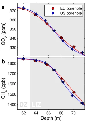
Fig. 2.Comparison of(a)CO2and(b)CH4data in the lock-in zone of the two boreholes. Data from three laboratories are averaged; the 1σuncertainty bar is a combination of analytical and sampling uncertainties as specified in Sect. 2.7. Curves are modeled profiles using the CIC model, see Sect. 3.3.
2.6 Differences between the EU and US boreholes
Though the boreholes are separated by a mere 64 m, within the lock-in zone we find differences in the mixing ra-tio profiles for CO2, CH4 (Fig. 2) and SF6 (not shown)
that exceed the estimated uncertainty of the combined sampling-measurement procedure (indicated with errorbar, see Sect. 2.7 for details). Note that we cannot make the same comparison for the other gas species since only data from the EU hole are available. The estimated uncertainty on the depth measurements is 5 cm, whereas at certain depths an error of 50–60 cm is required to explain the observed borehole off-set. So although depth measurement errors can certainly con-tribute to the offset, they cannot explain the full magnitude of it. We attribute the differences to lateral inhomogeneity in the firn stratigraphy, possibly originating from surface wind fea-tures that have been preserved in the densification process. Because of these differences we have chosen to model both holes separately.
Furthermore, for SF6we observe a∼0.25 ppt offset in the
5–50 m depth range, contrary to the CO2and CH4profiles
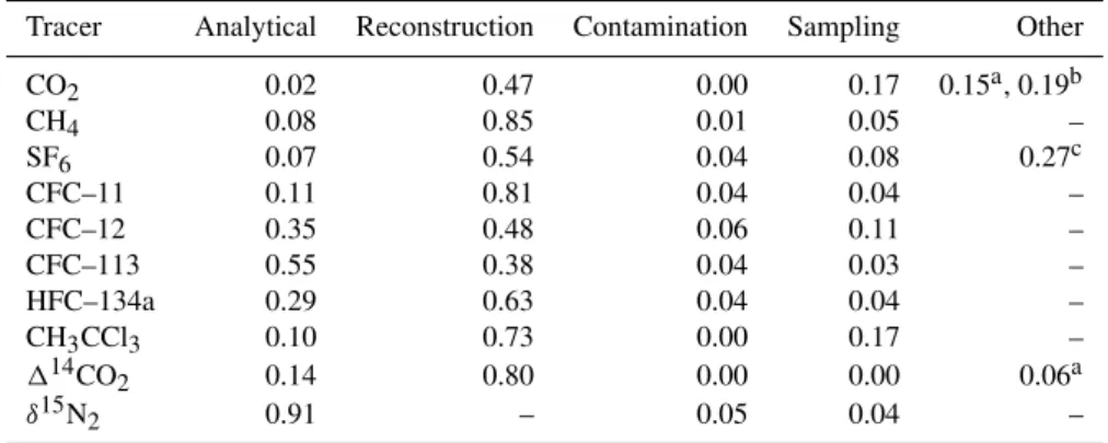
Table 2.Relative contributions to the total uncertainty, averaged over the firn column (EU borehole).
Tracer Analytical Reconstruction Contamination Sampling Other
CO2 0.02 0.47 0.00 0.17 0.15a, 0.19b
CH4 0.08 0.85 0.01 0.05 –
SF6 0.07 0.54 0.04 0.08 0.27c
CFC–11 0.11 0.81 0.04 0.04 –
CFC–12 0.35 0.48 0.06 0.11 –
CFC–113 0.55 0.38 0.04 0.03 –
HFC–134a 0.29 0.63 0.04 0.04 –
CH3CCl3 0.10 0.73 0.00 0.17 –
114CO2 0.14 0.80 0.00 0.00 0.06a
δ15N2 0.91 – 0.05 0.04 –
aIn-situ artifactsbUndersampling of seasonal cyclecEU-US borehole SF 6offset
flask flushing, sample contamination, procedural blanks and bladder outgassing, could all be excluded. Since we found no objective reason to reject data from either hole, we account for the discrepancy by assigning an additional errorbar to the SF6data from both holes in this depth range (see below). 2.7 Full uncertainty estimation∗
Having accurate uncertainty estimates is essential for our multiple-tracer methodology. A unique uncertainty estimate has been assigned to each of the 260 individual data points used in this study based on the following seven potential sources of uncertainty: (1) analytical precision as specified by the laboratories; (2) uncertainty in atmospheric recon-structions; (3) contamination with modern air in the deep-est firn samples; the deep-estimates are based on HFC-134a, SF6
and CFCs, which should be absent in the deepest sam-ples; (4) sampling effects estimated from inter-laboratory and inter-borehole offsets; (5) possibility of in-situ CO2artifacts
(e.g. Tschumi and Stauffer, 2000) and CO2enrichment due
to close-off fractionation (Huber et al., 2006; Severinghaus and Battle, 2006); (6) undersampling of seasonal cycle in the monthly atmospheric reconstruction (CO2only); and (7)
large unexplained EU-US borehole difference in the diffusive zone (SF6only).
The errors are assumed to be independent of each other. The uncertainties in the atmospheric reconstructions are con-verted from a time scale to a depth scale by running them through the CIC firn air model (Sect. 3.2). Details are given in the Supplement. The relative contribution of the seven sources, averaged over the firn column, is given in Table 2. For most tracers the atmospheric reconstruction is the largest contributor to the total uncertainty, followed by the analytical precision.
3 Modeling firn air transport at NEEM
3.1 Tuning of the diffusivity profile∗
How the diffusive transport changes with depth needs to be reconstructed through an inverse method for each firn air site independently. The procedure consists of forcing the trans-port models with the atmospheric history of one or several selected reference tracer(s), and subsequently optimising the fit to the measured mixing ratios in the firn by adjusting the effective diffusivity values at each depth (Rommelaere et al., 1997; Trudinger et al., 2002; Sugawara et al., 2003).
Here we will use diffusion as a generic term for mass trans-fer processes that are driven by a concentration gradient, and well described by Fick’s law. The diffusivity profile we re-construct is composed of two parts:
Molecular diffusionis a microscopic process originating in the thermal motion of the molecules constituting the firn air. The effective molecular diffusion coefficient of gases in the open porosity decreases with depth as the diffusive path be-comes increasingly tortuous due to the densification process (Schwander et al., 1988). The diffusion coefficient of gasX at depthzis given by
DX(z)=sop
D0X
τ (z)=sopγX D0CO
2
τ (z) (3)
whereDX0 is the diffusion coefficient in free air,τ (z)is the tortuosity at depthz, andγX=DX/DCO2 is the ratio of
dif-fusion coefficients (Trudinger et al., 1997). It is clear from Eq. (3) that the molecular diffusivity profiles for the different gas species scale linearly with each other. TheγXused in this
study are based on measurements by Matsunaga et al. (1993, 1998, 2002a,b), or a theoretical formula (Chen and Othmer, 1962) for gas species where no experimental data are avail-able (Supplement).
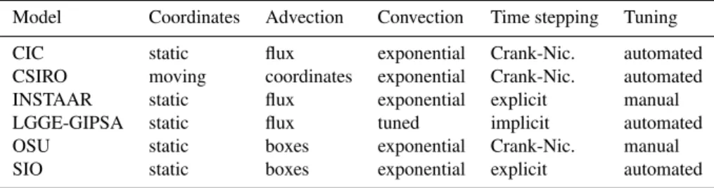
Table 3.Overview of firn air transport models. See text for explanation.
Model Coordinates Advection Convection Time stepping Tuning
CIC static flux exponential Crank-Nic. automated CSIRO moving coordinates exponential Crank-Nic. automated INSTAAR static flux exponential explicit manual LGGE-GIPSA static flux tuned implicit automated OSU static boxes exponential Crank-Nic. manual SIO static boxes exponential explicit automated
of a diffusion coefficientDeddy(z). Unlike molecular
diffu-sion,Deddy is equal for all gases as the process is
macro-scopic in origin. The first contribution toDeddyis convective
mixing in the top few meters due to seasonal temperature gradients and wind pumping (Colbeck, 1989; Severinghaus et al., 2001; Kawamura et al., 2006). Some of the models also include aDeddyterm in the deep firn to represent
disper-sive mass transfer. The classical example of disperdisper-sive mix-ing is Taylor dispersion, where (viscous) shear flow in a cir-cular tube enhances the effective diffusivity of a solute (Aris, 1956). Viscous flow can be induced in the deep firn by low frequency pressure fluctuations at the surface (Schwander, 1989), as well as air expulsion due to pore compaction (Rom-melaere et al., 1997). In soils, viscous flow induced by atmo-spheric pressure fluctuations has been shown to be an im-portant transport mechanism (Massmann and Farrier, 1992). Pore compaction causes a non-uniform velocity distribution between air expelled upwards, and air remaining behind in the pores. This spread in velocities results in additional (dis-persive) mixing.
The extensive uncertainty analysis we introduced in Sect. 2.7 assesses how reliable each data point is, and con-sequently how much weight should be assigned to it in the tuning procedure. This allows us to combine multiple tracers in the tuning, and the final reconstructed diffusivity profile is a trade-off between the constraints placed by the different tracers. All models in this study tuned their effective diffu-sivity profiles to minimise the root mean square deviation
RMSD= 1
N
N
X
i=1
(mi−di)2
σi2
!12
(4)
where thedi are the data for a given borehole (all tracers),
mi are the linearly interpolated modeled values at the same
depths, andσi give the total uncertainties. The indexiruns
over all data points, where N=204 for the EU hole, and N=77 for the US hole.
3.2 Model description∗
Six 1-D firn air transport models are tuned to the NEEM 2008 firn air data in the way outlined above. The models (in alphabetical order) were developed at the Centre for Ice and Climate (CIC), Commonwealth Scientific and Industrial
Research Organisation (CSIRO, Trudinger et al., 1997), In-stitute of Arctic and Alpine Research (INSTAAR), Labora-toire de Glaciologie et G´eophysique de l’Environnement and Grenoble Image Parole Signal Automatique (LGGE-GIPSA, Witrant et al., 2011), Oregon State University (OSU) and the Scripps Institution of Oceanography (SIO, Severinghaus and Battle, 2006).
Table 3 summarises a selection of relevant model charac-teristics. The second column indicates the kind of coordinate system used by each model. The CSIRO model is unique in using a coordinate system that moves downwards with de-scending ice layers (Lagrangian coordinates), giving a down-ward ice velocity wice=0 relative to the reference frame.
The other models use a static (Eulerian) coordinate system where the surface stays at z=0 and the ice layers move down at a finite velocitywice=Aρ/ρice. The choice of
coor-dinate system has consequences for the way advection of air with the ice matrix is handled (third column). In the CSIRO model, the moving coordinate system automatically leads to advective transport without the need to include it explicitly. The models expressed in Eulerian coordinates use either an advective flux as described by Rommelaere et al. (1997), or use boxes of air that are shifted downwards at regular time intervals (Schwander et al., 1993). Convection (fourth col-umn) is handled in two different ways. The LGGE-GIPSA model uses aDeddy term that is tuned by the RMSD
min-imisation algorithm, in combination with zero gravitational fractionation forz <4 m. The other models use the parame-terisation of Kawamura et al. (2006) where aDeddyterm is included that falls off exponentially with depth. The fifth col-umn of Table 3 indicates whether the time stepping used in solving the diffusion equation was either explicit (Euler for-ward), implicit (Euler backward) or mixed implicit-explicit (Crank-Nicolson method). Finally, some of the models were tuned through manual adjustments of the diffusivity profile, while others used an automated control method (e.g. Rom-melaere et al., 1997; Trudinger et al., 2002).
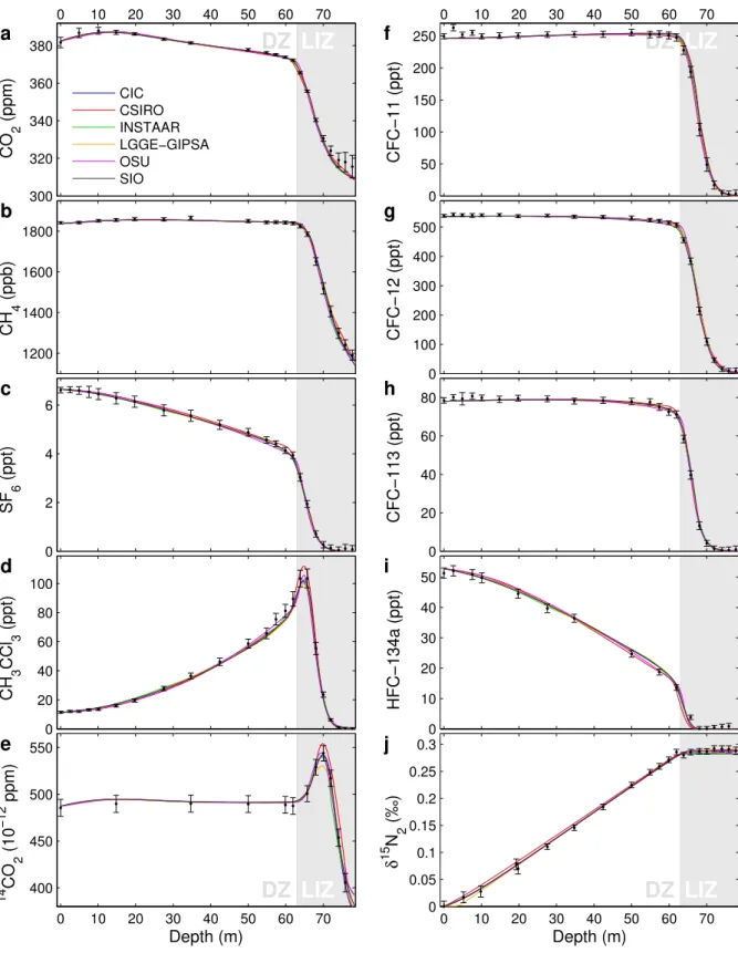
3.3 Fit of modeled profiles to the data∗
LIZ
DZ
0 10 20 30 40 50 60 70
300 320 340 360 380
CIC CSIRO INSTAAR LGGE−GIPSA OSU
SIO
1200 1400 1600 1800
0 2 4 6
0 20 40 60 80 100
LIZ
DZ
0 10 20 30 40 50 60 70
400 450 500 550
Depth (m)
LIZ
DZ
0 10 20 30 40 50 60 70
0 50 100 150 200 250
0 100 200 300 400 500
0 20 40 60 80
0 10 20 30 40 50
LIZ
DZ
0 10 20 30 40 50 60 70
0 0.05 0.1 0.15 0.2 0.25 0.3
Depth (m)
CO
2
(ppm)
CH
4
(ppb)
SF
6
(ppt)
CH
3
CCl
3
(ppt)
14
CO
2
(10
−12
ppm)
CFC−11 (ppt)
CFC−12 (ppt)
CFC−113 (ppt)
HFC−134a (ppt)
δ
15
N 2
(‰)
a
b
c
d
e
f
g
h
i
j
−4 −2 0 2 4
0 10 20
30 CIC RMSD= 0.73
Counts
−4 −2 0 2 4
0 10 20
30 CSIRO RMSD= 0.92
Counts
0 10 20
30 INSTAAR
RMSD= 0.78
Counts
0 10 20
30 LGGE−GIPSA
RMSD= 0.74
Counts
−4 −2 0 2 4
0 10 20
30 OSU
RMSD= 0.92
(Model−data) / σ
Counts
−4 −2 0 2 4
0 10 20
30 SIO
RMSD= 0.80
(Model−data) / σ
Counts
a
b
c
d
e
f
Fig. 4. (a–f)Histogram of(mi−di)/σi for the firn air transport models in this study using the EU borehole data. The black curve gives a Gaussian distribution of widthσ=1, normalised to have equal surface to the histogram. The RMSD is calculated using Eq. (4).
For CO2 (Fig. 3a) we find a pronounced mismatch for
z >70 m which is reproduced consistently by all models and in both boreholes. The atmospheric reconstruction is based on the Law Dome record (Etheridge et al., 1996), and consequently the largest source of uncertainty is the in-terhemispheric CO2 gradient. To explain the observed
mis-match with an error in the atmospheric history would re-quire a 6 ppm interhemispheric gradient in the 1950s, which can be ruled out (Keeling et al., 2010). Also contamination with modern air can be ruled out for these flasks, based on measurements of halocarbons. We cannot, however, ex-clude in-situ production of CO2from, e.g. organic material
or (bi)carbonates found in Greenland ice (e.g. Tschumi and Stauffer, 2000). There might also be a small close-off frac-tionation of CO2, of order 1 ‰ or less, based on its effective
molecular diameter (Huber et al., 2006; Severinghaus and Battle, 2006).
Both CH3CCl3and14CO2(Fig. 3d–e) have a peak within
the LIZ. The peak height and position, which are sensitive to the shape and magnitude of the diffusivity profile, provide an important constraint in the tuning procedure. It is exactly at
these peaks that the divergence between the models is most easily visible. It must be noted, however, that equally large model differences are found for other tracers as well (e.g. CO2and HFC-134a). Furthermore, models that fit the peak
height exactly do not necessarily provide the best overall fit to the data.
To quantitatively assess how well the modeled profiles fit the data, we make a histogram of (mi−di)/σi where the
index i goes over all 204 data points of the EU borehole. Theσi are the unique uncertainties we assigned to each data
LIZ
DZ
0 10 20 30 40 50 60 70
0 0.5 1 1.5
10−9 10−8 10−7 10−6 10−5
CIC CSIRO INSTAAR LGGE−GIPSA OSU
SIO
0 10 20 30 40 50 60 70
0 0.2 0.4 0.6 0.8 1
Depth (m)
a
b
c
D CO2(10
−5
m
2 /s)
D total
(m
2 /s)
D eddy
/
D total
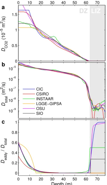
Fig. 5. (a)CO2molecular diffusivity profile with depthDCO2(z)for
the EU borehole.(b)Semi-log plot of the total CO2diffusivity pro-fileDtotal(z)=DCO2(z)+Deddy. (c)Plot ofDeddy(z)/Dtotal(z). Eddy diffusion near the surface corresponds to convective mix-ing; in the LIZ some of the models include dispersive mixing. The CSIRO model has zero eddy diffusivity in the LIZ; the line is not visible as the LGGE-GIPSA model is plotted on top of it.
Two models stand out as having a larger RMSD of 0.92 (CSIRO and OSU). For the CSIRO model this is caused by the absence of a back flow due to pore compression in the transport description (Sect. 4.4.4). For the OSU model we attribute the larger RMSD to the tuning procedure for the molecular diffusivity, which has fewer degrees of freedom than the procedures used by the other models (Supplement). Differences in RMSD give information on the perfor-mance of models, or model configurations, relative to each other; the RMSD as defined by Eq. (4) should not be inter-preted in an absolute sense.
LIZ
DZ
40 50 60 70
400 450 500 550 600
Depth (m)
14
CO
2
(
×
10
−12
ppm)
no LIZ diffusion with LIZ diffusion
Fig. 6.Modeled14CO2profiles both with, and without diffusivity
in the LIZ. Calculations done with the CIC firn air model.
4 Model intercomparison and discussion
4.1 Diffusivity profiles∗
All the models are tuned separately to optimise the fit to the data. Figure 5a shows the reconstructed molecular diffusivity profiles for CO2. The spread between the solutions is caused
by two factors. First, it reflects differences in model physics, which are compensated for by adjustments to the diffusivity profile. Second, it relates to the degree in which the inverse problem of diffusivity reconstruction is under-determined. By using 10 different tracers the problem is more strongly constrained than in the case of using only CO2, but the
solu-tion is not unique.
A second important observation is that all models require a non-vanishing diffusivity on the order of 2×10⁻⁹m2s−1
within the LIZ (see Fig. 5b). This contradicts the notion that diffusivity vanishes completely in the LIZ due to the pres-ence of impermeable layers, which is frequently expressed in the firn air literature (e.g. Battle et al., 1996; Trudinger et al., 2002; Assonov et al., 2005). Our findings confirm a re-cent study at Megadunes, Antarctica, that also reports a finite (eddy) diffusivity in the LIZ (Severinghaus et al., 2010). We believe this result to be robust, since it is reproduced by all six firn air models. In particular, the well reproduced height of the14CO2bomb spike, which falls entirely within the LIZ,
provides strong evidence for finite LIZ diffusion at NEEM; letting diffusivity go to zero leads to a14CO2peak that is too
narrow and overshoots the measured values by∼7σ(Fig. 6). How the LIZ diffusivity is parameterised, however, varies strongly among the models as shown in Fig. 5c. The models use either molecular diffusion, dispersive mixing (eddy dif-fusion) or a mixture of both. To fit theδ15N2data, most
19800 1985 1990 1995 2000 2005 2010 2
4 6 8 10 12 14
Year
z = 63 m
CIC CSIRO INSTAAR LGGE−GIPSA OSU
SIO
18800 1900 1920 1940 1960 1980
1 2 3 4
Year
z = 78 m
Density (
×
10
−2
yr
−1
)
Density (
×
10
−2
yr
−1
)
a
b
Fig. 7. EU borehole modeled CO2 age distribution densities for (a)depthz=63 m (lock-in depth) and(b) depthz=78 m (bot-tom of LIZ). On the horizontal axis are calendar years C.E.; dec-imal sampling year is 2008.54 (i.e. mid July). Age distributions are calculated by applying a surface forcing which is unity for 0.2≤t <0.4 yr, and zero elsewhere.
fractionation. The LGGE-GIPSA model circumvents this problem by using a combination of Fick’s and Darcy’s trans-port to describe almost stagnant transtrans-port in the lower zones (Witrant et al., 2011), which allows for using purely molec-ular diffusion in the LIZ. The SIO model uses the ratio of eddy to molecular diffusion in the LIZ as a tuning parame-ter in the RMSD minimisation, and finds that the fit is op-timised for 27 % eddy diffusion (Supplement). Models that reproduce the observations equally well can have completely different parameterisations, so our analysis does not tell us which scheme is more likely to be correct. These model dif-ferences do have important consequences for the modeling of isotopic ratios, as is discussed in Sect. 4.4.1.
LIZ
DZ
0 10 20 30 40 50 60 70
10−9 10−8 10−7 10−6 10−5
Depth (m)
EU borehole
US borehole
19000 1920 1940 1960 1980 2000
2 4 6 8 10 12
z = 63 m
z = 76 m
Year
a
b
D
total(m
2
s
−1
)
Density (
×
10
−2
yr
−1
)
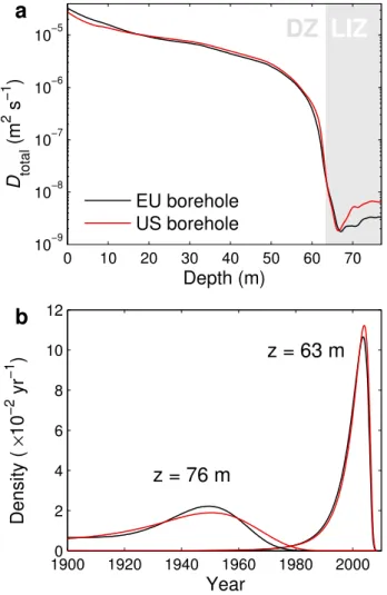
Fig. 8.Comparison between the EU and US boreholes.(a) Semi-log plot of the total CO2diffusivity profileDtotal(z)=DCO2(z)+
Deddy(z) averaged over all six firn models.(b)Age distributions at depthsz=63 m (lock-in depth) andz=76 m (bottom of LIZ) averaged over five firn models. The CSIRO model is excluded in the age distribution comparison as the US age distribution atz=76 m is unreliable (Supplement).
4.2 Gas age distributions∗
Firn air does not have a single age, but rather a distribution of ages (Schwander et al., 1993). The modeled gas age dis-tribution, also referred to as Green’s function, transfer func-tion, response function or age spectrum, provides a complete description of the model transport properties (Rommelaere et al., 1997). Figure 7 compares CO2age distribution
The LIZ lies between the two depths depicted here. From the closed porosity parameterisation (Eq. 1), we find that
∼95 % of the air is trapped in this zone. The gas age dis-tribution found in NEEM ice below the full close-off depth (sop=0) will be intermediate to these two end members,
with a tail of older air trapped already in the DZ. Interest-ingly, at the lock-in depth (z=63 m), estimates of both the age and the distribution width show a spread of around 25 % between models that reproduce the data equally well. Clearly these properties are not as well determined as one would expect based on the similarity between the modeled curves of Fig. 3 alone. On traversing the LIZ toz=78 m the rela-tive spread in modeled ages is reduced; the absolute spread grows slightly to about 5 yr, though. The spread in distribu-tion widths remains large.
For the US borehole the spread in the calculated mean ages atz=63 m is even larger (41 %). This large spread is due to the fact that we have only four tracers on the US borehole, and therefore the mean ages are less strongly constrained by the data.
We can use the gas age distributions to calculate the NEEM modern day1age, i.e. the difference between gas age and ice age below the firn-ice transition. From annual layer counting and matching of reference horizons to the NGRIP GICC05 timescale (Rasmussen et al., 2006), the ice at depth z=63 (78) m is estimated to be 190.6 (252.5)±1 yr old (S. O. Rasmussen, personal communication, 2011). To calcu-late the true1age we would require the gas age in the closed porosity. With the model results of Table 4 we can only cal-culate1ageop, i.e. the difference between ice age and gas age
in the open pores. By averaging results from the six firn air models we find a1ageopof 181±2 and 183±2 yr atz=63
and 78 m, respectively. This shows that the LIZ, ice and air are aging at roughly the same rate with depth. An estimated 4–5 % of the air is already trapped above 63 m, which biases our air age estimate young. This air fraction can introduce an error of at most 8 yr. Based on these considerations, our best estimate of the true1age is 182+−39yr (181+−39yr) for the EU (US) borehole.
4.3 Borehole comparison
Here we compare the reconstructed diffusivity profiles and gas age distributions for the EU and US boreholes. Figure 8a shows the total diffusivity with depth for CO2 on a
semi-log scale, where we have averaged over the solutions from the different firn air models. We observe that the largest di-vergence between the boreholes occurs in the LIZ. Also the gas age distributions show divergence mainly in the LIZ. Fig-ure 8b shows the age distributions at two depths, where again the curves represent an average over model output from the different firn air models. At the lock-in depth (z=63 m) the age distributions of both boreholes are still very similar. Af-ter traversing the LIZ (z=76 m, chosen to be near the final sampling depth on the US hole), we find that the firn air in
Table 4.Mean age, Median age, Full Width at Half Maximum and Spectral Width (1, Eq. (1) in Trudinger et al., 2002) at the lock-in depth (z=63 m) and at the bottom of the LIZ (z=78 m). All values given in years. The 2σ standard deviation divided by the meanµ
gives a measure of the spread in the model results.
Model Mean Median FWHM 1
z=63 m
CIC 9.2 7.4 7.9 4.5
CSIRO 10.3 8.8 9.3 4.2 INSTAAR 8.7 7.0 7.4 4.2 LGGE-GIPSA 11.1 8.1 9.1 6.8
OSU 7.9 6.5 7.0 3.7
SIO 9.0 7.2 7.6 4.5
2σ/µ 0.25 0.22 0.23 0.47
z=78 m
CIC 70.9 69.4 30.1 9.8 CSIRO 67.6 66.0 24.8 8.3 INSTAAR 68.3 66.1 37.1 12.4 LGGE-GIPSA 72.8 70.4 36.8 12.5 OSU 67.5 65.7 33.3 10.8 SIO 69.5 67.7 32.2 10.5 2σ/µ 0.06 0.06 0.28 0.30
the US hole has undergone more diffusive mixing, leading to a broader distribution width. Note that these differences in transport properties appear to have only a minor impact on the1age calculated in Sect. 4.2.
0 10 20 30 40 50 60 70
−0.14 −0.12 −0.1 −0.08 −0.06 −0.04 −0.02 0
CIC CSIRO INSTAAR LGGE−GIPSA OSU
SIO
0 10 20 30 40 50 60 70
10−4 10−3 10−2 10−1 100
LIZ
DZ
0 10 20 30 40 50 60 70
0 0.05 0.1 0.15 0.2 0.25 0.3
Depth (m)
LIZ
DZ
0 10 20 30 40 50 60 70
0 200 400 600 800
Depth (m)
δ
13
CO
2
(‰)
δ
grav(‰)
Amplitude |c|
Age of air (yrs)
a
b
c
d
Fig. 9.Model comparison using the four diagnostic scenarios and diffusivity tuned to the EU borehole data.(a)Scenario I: diffusive frac-tionation for a hypothetical monotonic CO2increase.(b)Scenario II: attenuation of a 15 yr period sinusoidal CO2forcing with depth.(c)
Scenario III: gravitational enrichment for gasXwithD0X=0.025DCO0
2. Data show gravitational enrichment of
15N
2corrected for the effect
of thermal diffusion. See Supplement for details.(d)Scenario IV: mean age of gasY when using advective transport only (DY0=0, i.e. diffusion is absent). With the exception of S-III all scenarios were run with the effect of gravity turned off.
4.4 Synthetic diagnostic scenarios∗
To diagnose model properties further, we developed four synthetic scenarios that probe specific aspects of the model physics. We present the individual scenarios below, and dis-cuss the model differences they reveal.
4.4.1 Scenario I: diffusive fractionation
For gas species whose atmospheric mixing ratios change over time, the disequilibrium in the firn leads to an isotopic fractionation with depth, even in the absence of changes in at-mospheric isotopic composition (Trudinger et al., 1997). As a scenario we use a monotonic CO2increase of∼1 ppm yr−1
without seasonal cycle, chosen to resemble the current an-thropogenic increase (Keeling et al., 2010). The surface iso-topic ratio is kept fixed atδ13CO2=0. Because the13CO2
isotopologue has a lower diffusivity than the12CO2
isotopo-logue, it is transported less efficiently into the firn, leading to a depletion inδ13CO2with depth. Ice core and firn air records
need to be corrected for the effect of diffusive fractionation (DF). For example, the (site specific) corrections for the re-cent anthropogenic increase are∼0.1 ‰ forδ13CO2at DE08,
Law Dome (Francey et al., 1999), and 1.2 ‰ forδ13CH4at
WAIS-Divide (Mischler et al., 2009).
Figure 9a shows the modeled isotopic signal with depth for the different models. Results in the DZ are consistent, how-ever they diverge strongly once the LIZ is reached. Forδ13C of CO2, the observed range between the different model
so-lutions in the deepest firn is 0.05 ‰, which is around 40 % of the total DF signal. For isotopologues of CH4 the DF
disagreement we estimate an uncertainty of 0.5 ‰ for both δ13C and δD of CH4. For δD of CH4 this uncertainty is
smaller than the typical measurement uncertainty, as well as the atmospheric signal observed in the firn (Br¨aunlich et al., 2001; Mischler et al., 2009). However, for bothδ13CO2and
δ13CH4the model disagreement exceeds the typical
instru-mental precision. At this moment we have no objective way of determining which of the models predicts the DF correctly. This additional uncertainty should therefore be recognised when interpreting ice core and firn gas isotopic records of periods with rapid atmospheric variations. Sites with a thick LIZ, combined with a low accumulation rate, allow for re-constructing atmospheric mixing ratios further back in time. However, a thick LIZ also means a larger uncertainty in DF (and thereby isotopic reconstruction) due to the poorly con-strained LIZ transport.
Molecular diffusion leads to DF between isotopologues because their diffusion coefficients are different. Advection, convection and dispersive mass transfer do not discriminate between isotopologues, and consequently do not fraction-ate the gas mixture. The observed model disagreement orig-inates in the way in which LIZ transport is parameterised (Fig. 5c). The CIC and OSU models both change from purely molecular diffusion in the DZ to purely eddy diffusion in the LIZ. Once the molecular diffusion approaches zero (and Deddy≫DX), the DF ceases to increase with depth giving a
horizontal line. The LGGE-GIPSA model, on the other hand, uses molecular diffusion all the way down to the close-off depth, giving a continued fractionation with depth. One way the DF uncertainty could be incorporated in future studies is by testing different parameterisations for LIZ diffusion, or by using transfer functions generated by different models.
The Law Dome-based records ofδ13CO2(Francey et al.,
1999) andδ13CH4(Ferretti et al., 2005) were both corrected
for the effects of DF. The correction should not be affected much by our findings here for several reasons. Most im-portantly, the accumulation rate (and therefore the advective flux) at the Law Dome DE08 and DE08-2 sites is very high. This strongly reduces DF in the LIZ. Furthermore, the LIZ is relatively thin (Trudinger, 2001). The study by Ferretti et al. (2005) combines ice core samples from the aforementioned high accumulation Law Dome sites with firn air measure-ments from the DSSW20K site, which has a rather low accu-mulation rate (∼0.16 m yr−1ice equivalent). After DF
cor-rection the results agree well. Other published firn air and ice core isotopic records that cover the recent anthropogenic in-crease have also been corrected for the effects of DF (e.g. Br¨aunlich et al., 2001; Sugawara et al., 2003; R¨ockmann et al., 2003; Sowers et al., 2005; Bernard et al., 2006; Ishi-jima et al., 2007; Mischler et al., 2009). Until the true nature of LIZ mixing is better understood, there is no way of know-ing whether the DF magnitude calculated in these studies is correct. Our findings imply that the uncertainty in these at-mospheric reconstructions might have been underestimated.
4.4.2 Scenario II: attenuation of a sine wave with depth
Rapid atmospheric variations are attenuated in the firn, and recorded in the ice with a reduced amplitude (Spahni et al., 2003). To compare the firn smoothing effect between the models, we force them with a sinusoidal atmospheric vari-ation in CO2 that has a 15 yr period. Due to diffusion, the
amplitude of the signal decreases with depth in the firn. For mathematical convenience we impose two separate atmo-spheric scenarios:
[C1](t, z=0)=1+sin(2π t /15)
[C2](t, z=0)=1+cos(2π t /15)
wheret is the time in years. Note that both signals are at-tenuated to the same degree, and that theπ/2 phase angle between them is preserved. To get the signal amplitude with depth, we combine them in the following way:
|[C](t, z)| =p([C1](t, z)−1)2+([C2](t, z)−1)2. (5)
The outcome is shown in Fig. 9b. We observe that signal at-tenuation in the LIZ is stronger than in the DZ. This is be-cause transport in the DZ is efficient; the mean CO2age at
the lock-in depth is around 9 yr, which is less than the period of the atmospheric oscillation. The mixing ratios in most of the DZ will be “in phase” with the atmospheric signal, giv-ing little attenuation. By comparison, air in the LIZ is nearly stagnant. It takes around 60 yr to be transported over 15 m, corresponding to 4 periods of the sinusoid. As air of differ-ent ages (i.e. differdiffer-ent phases of the atmospheric cycle) gets mixed, the signal amplitude is reduced.
Within the DZ the models agree well. In the LIZ there are two intervals (65< z <68 m and 74< z <78 m) where the CSIRO model has significantly less attenuation with depth. These intervals correspond to the depths where the recon-structed CSIRO diffusivity goes to zero (Fig. 5b). On the US borehole this effect is even more pronounced (Supplement).
In Sect. 4.1 we touched upon the question of whether or not there is continued diffusion in the LIZ; our diffusivity reconstructions indicate that there is at NEEM. Scenario II shows that this remnant LIZ diffusivity causes very strong attenuation of the atmospheric signal. Therefore, the ques-tion of LIZ diffusivity has important consequences for the temporal resolution at which we can hope to reconstruct at-mospheric variations back in time using ice cores.
4.4.3 Scenario III: balance of transport fluxes
The total gas flux is the sum of the advective, diffusive and convective fluxes. Within the DZ, molecular diffusion over-whelms the other transport mechanisms; in this scenario we bring the different fluxes into balance by considering a hypo-thetical gasXwith a very small diffusion coefficientD0X=
0.025D0CO
2, and a massMX=Mair+1×10
−3kg mol−1. The
gravitational enrichment with depth. This is the only of the four scenarios where gravity is turned on in the model runs.
Figure 9c shows the model output together with the true gravitational enrichment as measured for15N2. In
thermody-namic equilibrium the enrichment is given by the baromet-ric equation:δgrav(z)= [exp(1Mgz/RT )−1] ≈1Mgz/RT
(Sowers et al., 1992). The advective and convective fluxes drive the air column out of equilibrium reducingδgrav(z)
be-low the barometric case. For gasX the diffusive flux is not large enough to oppose the other two, leading to a finalδgrav
which is about half that of15N2. In this way the enrichment
with depth represents the balance between diffusion on one hand, and advection and convection on the other.
The differences in implementation of the convective mix-ing are clearly visible. The LGGE-GIPSA model uses no gravitational enrichment in the top 4 m, followed by a tuned eddy diffusion. The convective mixing in the other mod-els, which all use the parameterisation by Kawamura et al. (2006), penetrates much deeper into the firn. In the DZ there are also clear differences; here the gravitational slope mostly represents the balance between diffusion and advection. The CSIRO has a stronger advection term due to the absence of pore compression back flow (see below); this is reflected in a more reduced slope. A higher advective flux can partially be compensated in the diffusivity tuning by a lower diffusivity, and vice versa. This explains why the diffusivity profile re-constructed through the CSIRO model is slightly lower than those of the other models (see Fig. 5a).
4.4.4 Scenario IV: advective transport
Pore closure traps air in bubbles, which are subsequently ad-vected downwards with the ice matrix. A downward flux of air in the open pores compensates for this removal process in the firn-ice transition. In the last scenario we study hypotheti-cal gasY, which is not subject to diffusion or convection, and is transported into the firn by the advective flux alone. Both eddy and molecular diffusion are set to zero. Its atmospheric history is a linear decrease by 1 ppm yr−1, until it reaches
zero at the final model date. This leads to a mixing ratio of gasY in the firn that equals the age of the air at each depth. The results are shown in Fig. 9d. In the absence of diffusion, most models find an age of around 900 yr at the bottom of the firn column. The CSIRO model stands out with a much lower gas age. Differences in total air flux, and thereby the total air content in mature ice, affect the advective transport. Also, artificial numerical diffusion in the models reduces the calculated gas ages.
There are significant differences in the way advective transport is treated by the models. The key difference is whether or not the model includes an upward air flow rel-ative to descending ice layers to account for compression of open pores (Rommelaere et al., 1997; Sugawara et al., 2003). Note that this term is smaller than|wice|, and that the net air
flow in the open pores is always downwards. The
compres-sion term is neglected in the CSIRO model (Trudinger et al., 1997), which leads to a gas age that equals the ice age (since wair=wice). Note also that the observed difference is not
re-lated to the choice of reference frame (static vs. moving). In the LIZ air transport is dominated by advection, so this is where we expect to see the effect of the back flow most clearly. Indeed we see that in the LIZ the CSIRO model di-verges most strongly from the other models, e.g. in the total reconstructed diffusivity (Fig. 5b) and the diffusive smooth-ing of scenario II (Fig. 9b).
Neglecting the back flow term corresponds to a physical model of the firn where all the air is transported downwards with the ice layers. This would be possible if, e.g. the denser firn layers succeed in completely sealing off the air below (Martinerie et al., 1992; Schwander et al., 1993). In the case such impermeable layers are present in the LIZ, pressure will build up in the pore space below. At some of the Law Dome sites (e.g. DSSW20K) outgassing was observed from freshly drilled boreholes, which could be caused by the venting of such pressurised pores to the atmosphere. However, at these sites the effects of wind pumping could not be excluded as the origin of the observed air flow. At NEEM, no outgassing from pressurised pores was observed. More evidence for the absence of sealing layers comes from the observation of dif-fusive mixing in the LIZ (Sect. 4.1). Finally, the total air con-tent implied by the assumption of fully pressurised pores in the LIZ is incompatible with observed air content in mature ice (Martinerie et al., 1992).
For these reasons we believe that at NEEM the back flow due to pore compression can not be neglected when describ-ing the firn air transport. This makes the assumptions in the CSIRO model invalid, explaining why it obtains a higher RMSD than most other models (Fig. 4). Preliminary tests show that by including the advective back flux in the CSIRO model the RMSD reduces to 0.74.
5 Summary and conclusions
We presented a new multi-tracer method for characterising the firn air transport properties of a site. We applied the method to NEEM, Northern Greenland, by tuning six firn air models to an ensemble of ten tracers. The firn air models used in this study were able to fit the data within a 1-σ nor-mal distribution, meaning that the site can be modeled con-sistently within the estimated uncertainties. Each of the refer-ence tracers constrains the firn profile differently through its unique atmospheric history and free air diffusivity, making our multiple-tracer characterisation method an improvement over the commonly used single-tracer tuning.
held notion that diffusive mixing is absent in the lock-in zone. A comparison between replicate boreholes located 64 m apart suggests that this lock-in zone diffusion is sen-sitive to lateral inhomogeneities in firn stratigraphy. Further-more, we find that despite the fact that the models reproduce the measured profiles equally well, the gas age distributions they calculate can differ substantially. Often-used quantities, such as the mean age and distribution width, differed among the models by up to 25 %. The modern day1age was calcu-lated to be 182+−39yr.
Finally, we introduced four diagnostic scenarios that are designed to probe specific aspects of the model physics, from which we can draw two main conclusions. First, we studied the consequences of the different ways in which the mod-els implement advection, in particular whether they include a back flow term to account for pore compression. Includ-ing the back flow term significantly improves the fit to the data, suggesting this term can not be neglected, as is done in the CSIRO model. Second, we find that the effect of isotopic diffusive fractionation is poorly constrained by the models. Near the close-off depth, the calculated diffusive fractiona-tion differs by 40 % between the models. These differences are related to the way in which lock-in zone diffusion is pa-rameterised. Molecular diffusion leads to continued fraction-ation, whereas dispersive transport (eddy diffusion) does not. Further work is needed to elucidate the true nature of lock-in zone diffusion. Meanwhile, when interpreting firn air and ice core isotopic records, an additional uncertainty needs to be included to account for the model discrepancy found here.
Supplementary material related to this article is
available online at: http://www.atmos-chem-phys.net/12/ 4259/2012/acp-12-4259-2012-supplement.zip.
Acknowledgements. We would like to thank Stephen Montzka, Bradley Hall and Geoff Dutton from NOAA-ESRL for providing halocarbon and SF6 atmospheric data and for their help on gas
calibration scales; Ray Weiss and Ray Wang for their kind help on AGAGE atmospheric data and calibration scales; Paul Krummel for providing NOAA/AGAGE(SIO) concentration ratios for halocarbon species based on flask and in-situ measurements; Bradley Hall for providing IHALACE results prior to their publication. Comments and suggestions by three anonymous referees improved the manuscript considerably. This work ben-efited greatly from numerous data available in public databases, in particular: AGAGE (http://cdiac.ornl.gov/ndps/alegage.html), NOAA ESRL (http://www.esrl.noaa.gov/gmd) and EDGAR (http://www.rivm.nl/edgar). We thank the people involved in the acquiring, analysis, and accessibility of these data. NEEM is directed and organised by the Center for Ice and Climate at the Niels Bohr Institute and US NSF, Office of Polar Programs. It is supported by funding agencies and institutions in Belgium (FNRS-CFB and FWO), Canada (GSC), China (CAS), Denmark
(FIST), France (IPEV, CNRS/INSU, CEA and ANR), Germany (AWI), Iceland (RannIs), Japan (NIPR), Korea (KOPRI), The Netherlands (NWO/ALW), Sweden (VR), Switzerland (SNF), United Kingdom (NERC) and the USA (US NSF, Office of Polar Programs). C. Buizert would like to thank Bruce Vaughn (IN-STAAR, University of Colorado) for his hospitality and support; V. V. Petrenko has been supported by the NOAA Postdoctoral Fellowship in Climate and Global Change and NSF grants 0632222 and 0806387 (White); A. J. Orsi and J. P. Severinghaus were supported by NSF 0806377; UEA acknowledges NERC for awards NE/F021194/1, NE/F015585/1 and a PhD Studentship (Hogan); the CSIRO contributions to this work were partly supported by the Australian Climate Change Science Program, funded jointly by the Department of Climate Change and Energy Efficiency, the Bureau of Meteorology and CSIRO; the French contribution to this study was further supported by CNRS through INSIS/PEPS-automatique and INSU/LEFE programs.
Edited by: R. van de Wal
References
Aris, R.: On the dispersion of a solute in a fluid flowing through a tube, Proc. R. Soc. Lond. A, 235, 67–77, 1956.
Arnaud, L., Barnola, J. M., and Duval, P.: Physical modeling of the densification of snow/firn and ice in the upper part of polar ice sheets, in: Physics of Ice Core Records, edited by Hondoh, T., 285–305, Hokkaido University Press, 2000.
Assonov, S. S., Brenninkmeijer, C. A. M., and Jockel, P.: The O-18 isotope exchange rate between firn air CO2and the firn matrix
at three Antarctic sites, J. Geophys. Res.-Atmos., 110, D18310, doi:10.1029/2005jd005769, 2005.
Assonov, S. S., Brenninkmeijer, C. A. M., J¨ockel, P., Mulvaney, R., Bernard, S., and Chappellaz, J.: Evidence for a CO increase in the SH during the 20th century based on firn air samples from Berkner Island, Antarctica, Atmos. Chem. Phys., 7, 295–308, doi:10.5194/acp-7-295-2007, 2007.
Aydin, M., Saltzman, E. S., De Bruyn, W. J., Montzka, S. A., Butler, J. H., and Battle, M.: Atmospheric variability of methyl chloride during the last 300 years from an Antarctic ice core and firn air, Geophys. Res. Lett., 31, L02109, doi:10.1029/2003gl018750, 2004.
Battle, M., Bender, M., Sowers, T., Tans, P. P., Butler, J. H., Elkins, J. W., Ellis, J. T., Conway, T., Zhang, N., Lang, P., and Clar-ket, A. D.: Atmospheric gas concentrations over the past century measured in air from firn at the South Pole, Nature, 383, 231– 235, doi:10.1038/383231a0, 1996.
Bernard, S., R¨ockmann, T., Kaiser, J., Barnola, J.-M., Fischer, H., Blunier, T., and Chappellaz, J.: Constraints on N2O bud-get changes since pre-industrial time from new firn air and ice core isotope measurements, Atmos. Chem. Phys., 6, 493–503, doi:10.5194/acp-6-493-2006, 2006.