*e-mail: [email protected]
1. Introduction
The demands for lighter weight and power-saving and recyclable parts have increased recently. Magnesium alloys have become alternatives to steel, aluminum and plastics for some products1,2. Extrusion is a bulk-forming process and the most common extrusion process. It works by placing the preheated billet in a container. The billet is pushed out of the extrusion die by a ram. There is a reusable dummy block between the ram and the billet to keep them separated. The major disadvantage of this process is that the force required to extrude the billet is greater than which are needed in the indirect extrusion process.
Direct Extrusion is a common plastic forming method to improve formability and strength of magnesium alloys by reining the microstructures. With regard to the hexagonal close-packed (HCP) structure, the cold-plasticity of magnesium alloy is low3. One of the promising methods for increasing ductility and strength in magnesium alloy is through microstructure reinement. A ine-grained material is harder and stronger because it has a greater total grain boundary area to impede dislocation motion4. Matsuyama et al. used a new processing procedure to extrude a cast Mg-9% Al alloy involving the sequential application of extrusion and equal-channel angular pressing (EX-ECAP)5. Experiments showed that the Mg-9% Al alloy has an initial grain size
of ~50 μm after casting but this was reduced to ~12 μm after extrusion and it was further reduced to ~0.7 μm when the extruded alloy was subjected to ECAP for 2 passes at 473 K. Although the cast alloy exhibits extremely limited ductility and the extruded alloy was only moderately ductile. The EX-ECAP usually includes more than 2 steps, and the material endures intricate diversiication of forming environments including process temperature and may be oxidized. Matsubara et al. used the EX-ECAP to prepare for the ultraine magnesium alloy6,7, but the ECAP process was only used in the lab scale processing and preparation for nanocrystalline material, there exited an unbridgeable gap between the experimentation and applications of industry.
The current research team has engaged in the researches of the extrusion-shear (ES) process which included initial forward extrusion and shearing process subsequently as early as 20088.The authors9,10 have put forward ES extrusion technology which combines the characteristics of direct extrusion and two pass equal channel extrusion. The experiments of ES process and direct extrusion have been performed, and direct extrusion and ES dies suitable for industrial horizontal extruder have been designed and manufactured. ES process can improve workability and strength of magnesium alloys by reining the grain structure. But in the ES process of AZ31 magnesium alloy, it is dificult to produce rods without surface
Crack Propagation Analysis of Magnesium Rod Processed by Extrusion-shear:
Numerical Modeling and Experimental Veriication
Hong Jun Hua, Hao Wanga*, Ding Fei Zhangb, Qingwei Daib,c, Jin Lin Daia, Ming BoYanga
aChongqing University of Technology, Chongqing, 400050, China
bChongqing University, Chongqing, 400045, China
cSchool of Metallurgy and Materials Engineering, Chongqing University of Science and Technology,
Chongqing, 401331, China
Received: July 5, 2015; Revised: July 6, 2015
During extrusion-shear (ES) process, the surface cracks would be formed in the processed rod for AZ31 magnesium caused by nonhomogeneous metal low and stress. To reduce the cracks defects, three-dimensional (3D) inite element method (FEM) of ES on a wrought AZ31 magnesium alloy have been performed. ES process experiments have been also conducted to verify the simulation results under the identical conditions. It can be found that the tendency to generate the dead zone is decreased by employing the ES die with the extrusion ratio of 28 comparing to the one with the extrusion ratio of 11.6. With the extrusion ratio 28, the surface stresses of the rod at the die exit are decreased greatly so that the surface cracks are avoided. The ES die with the extrusion ratio of 28 would increase temperature on the rod surface and subsequently result in the sacriice of the tensile strength of the AZ31 rod. Damage model has been chosen and Cockcroft–Latham damage factor has been set and incorporated into DEFORM software. The simulation results show that the larger extrusion ratio would have the smaller crack propagation. Experimental validation shows that the results of experiments are in accordance with those from computer simulation. The study indicates that FEM can be used conidently for designing ES dies and process parameters in CAE environment for DEFORM software to improve the product quality and productivity by avoiding trail runs.
defects. Thus, the improvement of the surface condition is required in order to reduce the production costs. There are three principal extrusion defects: surface cracks, internal cracks. If extrusion temperature, friction, or speed is too high, the surface temperatures would rise signiicantly, and subsequently the surface cracking and tearing may increase. These cracks are intergranular and are usually caused by hot shortness. These defects occur especially in magnesium alloys, although they may also occur in high temperature alloys. This defect can be avoided by lowering the billet temperatures and extrusion speeds. Surface cracking may also occur at lower temperatures. When the product being extruded sticks to the die land, the extrusion pressure increases rapidly. And than the product moves forward again and the pressure is released. Surface cracks appear if the surface of an extrusion splits. This is often caused by the extrusion temperature, friction, or speed being too high. It can also happen at lower temperatures if the extruded product temporarily sticks to the die. If the center of the extrusion develops cracks or voids there exits internal cracks. These cracks are attributed to a state of hydrostatic tensile stress at the centerline in the deformation zone in the die. Depending on material condition and on process variables, extruded products can develop several types of defects that can signiicantly affect their strength and product quality. The cycle is then repeated continually, producing periodic circumferential cracks on the surface. Because of the similarity in appearance to the surface of a bamboo stem which it causes, it is known as bamboo defects. The author11 have used 3D computer inite element (FE) simulations of extruding a wrought magnesium alloy AZ31 into rods have been performed and the results have been veriied in extrusion experiments under identical conditions, the research results showed tendency to generate the dead zone is decreased by employing the die angle 60º at the cone-shaped die comparing with the die angle 180º. The surface additional tensile stresses of the rod at the die exit are decreased greatly so that the surface cracks caused are avoided by using the die angle 60º. The extrusion die with die angle 180º would increase the higher temperature and possibility of crack formation on the rod surface that caused by die angle 60º and temperature rise decrease tensile strength of the AZ31 rod. The experimental results show that die angle 180 °could cause continuous cracks on the surface of the extruded rod. The extrusion force required is reduced approximately 15 ton by employing the die angle 60º.
In essence, for a certain billet material and extrudate proile, the results of the extrusion process and surface quality mainly depend on the thermo-mechanical phenomena. Understanding the cracks caused by different die structures is of great importance. Much of this understanding has been gained through computer simulation based on the inite element method (FEM) for direct extrusion and experimental veriication. However, there is very limited information available in the case of ES process. The parameters, such as low stress, strain, strain rate, and temperature, are not experimentally measurable. Information about these process variables is necessary to optimize the process but it is very dificult to obtain this information from experiments because the thermo-mechanical response of a magnesium alloy as affected by extrusion conditions is highly complex. The FEM
can be used to reduce the amount of try-out necessary to produce acceptable products.
The preceding studies using FEM as an eficient means undoubtedly contributed to gaining a fundamental understanding of the ES process for magnesium alloys. In the case of extruding round billets into rods, the relationships between surface quality and die structures and process parameters are lack. It is observed that the researches on computer simulation of ES process has been highly insuficient compared with direct extrusion.
In the present research, an attempt has been made to simulate the ES process. It concerned the characterization of the thermo-mechanical response of wrought magnesium alloys during ES process in term of temperature rise, stress and low velocity affected by different extrusion ratios. The metal low improved during ES extrusion processes is an important mean which increases the formability and eliminate defects such as cracks and bending. Many factors may inluence the metal low, among which the die structure is closely related to the metal low. Analysis of the ES die showed that different extrusion ratios inluence the rod quality greatly, and tend to cause the cracks of extrusion products. FE method can be used for the optimum design of the ES die and homogeneity of the metal low, stress distributions and damage predication can be predicted effectively.
2. Simulation and Experimental Details
2.1. Material prosperities
in Hongjun et al.11. The present study considers the following damage values such as Normalized C&L, Cockcroft and Latham, McClintock, Freudenthal, Ayada and Brozzo etc.
In order to calculate ductile fracture criteria destructive tests had been done and compression tests have been carried out. Cockcroft and Latham predicted that fracture occurs in a ductile material at a critical damage factor value C* of the damage factor C. The C-L criterion for ductile fracture during metalworking has been applied in conjunction with fracture strains measured from uniaxial tension tests. In uniaxial tension tests, in which sharp necks and high levels
of stress triaxiality were negligible. The fracture strain εf derived from the AZ31 stress-strain curve is approximately 0.45. Thus the value of C is 0.4511. The experimental results showed that the fracture model adapted in these simulations was Cockcroft and Latham fracture model in Equation (2) which value was set to 0.45.
2.2. Die structures
The die structure chart (a) and ES die (b) of the ES process could be seen in Figure 1. An ES die consists of direct extrusion and two continuous channels which have an equal round cross-section. The design of ES has been not well known or understood by the public. It is interpreted as that the technology or the mechanism regarding the ES die design and the plastic deformation has not been fully developed yet. In order to understand the behaviors of the plastic deformation for ES extrusion, two types of ES dies with different extrusion ratios have been designed and manufactured.
2.3. Finite element method
To save the computation time, only half of the workpiece and tooling with extrusion ratios 12 and 28 have been modeled as Figure 2a and Figure 2b respectively, taking advantage of their symmetry and assuming the symmetry planes to be immobile and no material movement across these planes. Simulation and experimental parameters including dimensions of billet and container are listed in Table 1, as well as the main process parameters used both in computer simulations and in extrusion experiments.
The geometric models formatted (Standard Template Library) STL were imported to the inite element program DEFORM-3D v.10 software package to establish the inite element meshes14. The original meshes of the billet and the cone-shaped die were divided as 20000 four-nodal elements. The simulation models consisted of 3 objects in the extrusion
press: the billet, the die with an aperture diameter of 82 mm and a bearing length of 5mm, and a rigid container.
2.4. Experiments
The low stress-strain data of the AZ31 alloy were determined through hot compression tests using Gleeble1500D machine. The low stress curves measured in these tests have been corrected and a set of low stress-strain curves are shown in Figure 3 as examples. The temperature ranged from
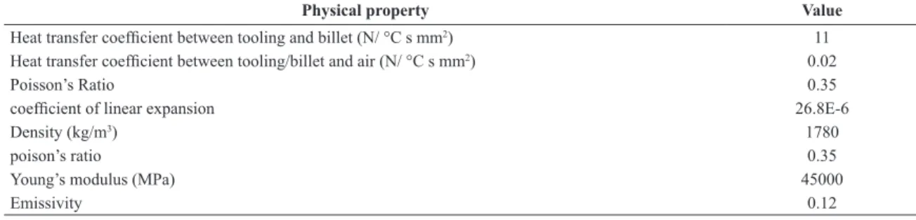
Table 1. Physical properties of the AZ31 workpiece.
Physical property Value
Heat transfer coeficient between tooling and billet (N/ °C s mm2) 11
Heat transfer coeficient between tooling/billet and air (N/ °C s mm2) 0.02
Poisson’s Ratio 0.35
coeficient of linear expansion 26.8E-6
Density (kg/m3) 1780
poison’s ratio 0.35
Young’s modulus (MPa) 45000
Emissivity 0.12
The ES dies with extrusion ratio 11.6 and 28 have been designed and manufactured respectively. Before extrusion the billets have been machined into rod with diameter of 80mm. Real extrusion experiments have been carried out by employing a press with a resistance heated heater. The die material, die and billet dimensions and extrusion conditions are all the same as those used in numerical simulation as described in Table 1 and Table 2.
3. Results and Discussion
ES processes have been simulated from the start of extrusion until the extrusion was steady state. In addition, the maximum extrusion forces have been counted under the different simulation conditions. The velocity and stress distributions and damage indexes of the billet as well as the deformation behavior of the billet have been predicted during ES process.
3.1. The homogeneity of metal low inluenced by
the different extrusion ratios for ES dies
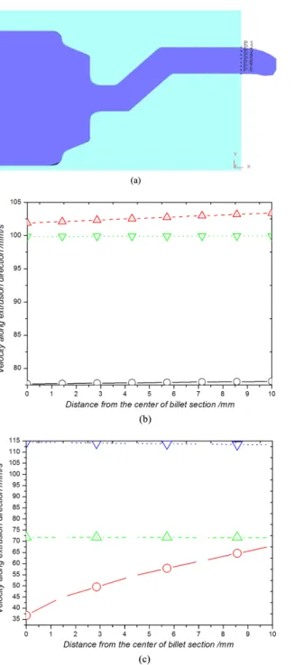
Optimization of the metal lows during ES processes is an important mean which increases the formability and eliminates defects. The nonhomogeneous metal low at the die exit would cause the extrusion defects such as cracks on surface of the extruded rods. Many factors may inluence the metal low, among which the die structures are closely related to none-homogeneity of metal lows. To study the nonhomogeneity of metal low inluenced by extrusion ratios, some investigated points (p1 to p8 shown in Figure 4a distributing along the radial direction at the die exit have been chosen. The low velocities along extrusion direction at the die exit with different extrusion ratios at the beginning of the steady extrusion stage have been illustrated in Figure 4b and Figure 4c. Conclusions can be drawn that the better homogeneous metal lowing along extrusion direction is caused by the ES die with the extrusion ratio 11.6, but the nonhomogeneous metal lows have been arisen by the larger extrusion ratio of 28.
3.2. Analysis of axial stresses
Figure 5 shows the comparison of the axial stress varying with time at investigated points (p1 to p4 shown in Figure 5 a) with the extrusion ratio 11.6 and 28 in Figure 5b and Figure 5c respectively. When the extrusion ratio 11.6 has been used, the axial stress on the surface is compressive stress mainly. It is clear that the point “p1” and point “p2” are applied primary tensile stress in the Figure 5b, But for points “p3” and “p4” there exits considerable compressive stress before extrusion time 2.3 s. But after that the compressive stress of point “p3” is translated into tensile stress rapidly. There are very differences among these points for stresses. But in the Figure 5c the stress of points are compressive stresses. It is concluded that the ES die with the extrusion ratio of 11.6 can’t produce surface cracks. For the friction at the ES die, the metal low is nonhomogeneous, which cause the generation of additional stress. The additional tensile stress increases with the development of ES process, and when it reached the fracture limit, the cracks would appear on the surface of rod. The best way to avoid the surface cracks is to decrease the axial additional stress15.
Figure 2. 3D FE model of dies and billet.
Figure 3. True stress/true strain curves obtained from the compression tests at different strain rates with the pre-set strain rate of 1 s−1.
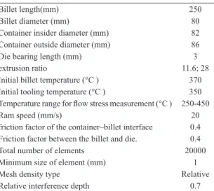
Table 2. Simulation and experimental parameters.
Billet length(mm) 250
Billet diameter (mm) 80
Container insider diameter (mm) 82 Container outside diameter (mm) 86
Die bearing length (mm) 3
extrusion ratio 11.6; 28
Initial billet temperature (°C ) 370 Initial tooling temperature (°C ) 350
Temperature range for low stress measurement (°C ) 250-450
Ram speed (mm/s) 20
friction factor of the container–billet interface 0.4
Friction factor between the billet and die. 0.4
Total number of elements 20000
Minimum size of element (mm) 1
Mesh density type Relative
Relative interference depth 0.7
250 °C to 400 °C, and a strain rate range of 0.01 to 10 s−1 have been input into the DEFORMTM -3D.
Figure 4. Flow velocities along extrusion direction at the die exit
with different dies. angles: (a) the investigated points at the die exit, ES extrusion with ratio of 11.6 (b), and 28 (c).
Figure 5. The axial stress along the extrusion direction varying with extrusion time at the surface point of the rod with points (a) for ES extrusion with the ratio of 11.6 (b) and 28 (c).
3.3. The inluences of extrusion ratio on
temperature rise for rod surface
The temperature is highest between the material/die interfaces due to friction force during ES process16. In this study, the frictional factors are the constant and equal to 0.4. The temperature rise of the rods depends on the different die structures including the contact area between the billet and die, and the size of the deformation zone. Figure 6 shows the variation of the maximum temperature increase along the
die-billet interface throughout an extrusion cycle with two different extrusion ratios. It can be founded that from the curve of maximum temperatures for ES die with extrusion ratio 11.6, the maximum temperature is near 389 °C, there exits a steep rise for maximum temperatures.
characteristics described on in temperature rise of billet are due to change in the heat generation. Surface temperatures rise signiicantly if the extrusion ratio is bigger, and this condition may cause surface cracking and tearing for the tensile strength of the AZ31 rod is decreased.
3.4. Analysis of surface damage
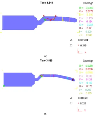
The cumulative effects of the tensile stress generated during ES process on the propensity for fracture can be quantiied through calculation of the Cockcroft-Latham damage factor C. Figure 7 represents the damage inclination indexes for extrusion ratio 11.6 and 28 at extrusion time 3.5 s. It can be seen that the index of the damage caused by ES
die with extrusion ratio 11.6 is as much as 0.348 and bigger than which has been induced by ES die with extrusion ratio 28. It is seen that the maximum damage occurs at the billet surface in the exit region of the die. This is because critical damage occurs at the point of maximum tensile stress in the rods. It can be concluded that the smaller extrusion ratio would cause bigger probability of cracks17-19.
Figure 8 shows comparison of damage values for four points tracking with different extrusion ratio 11.6 and 28. The four points are indicated in Figure 5a. It can be found that the damage value caused by ES die with extrusion ratio 11.6 is bigger than those induced by ES die with extrusion ratio 28. For the rod is extruded from the inside of die oriice to the outside the damage value increases continuously when the extrusion ratio is 11.6. For ES die with extrusion ratio 28 the damage value is the smaller at the points, so the cracks may produce most likely for ES extrusion with extrusion ratio 11.6.
3.5. Experimental validation
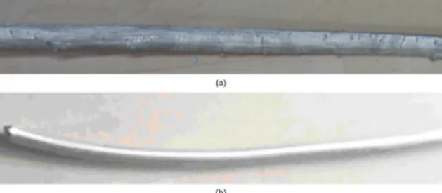
Typical cracks have been observed on an AZ31B rod extruded at temperature 370°C with extrusion ratio 11.6 shown in Figure 9a. It is clear that there are many cracks and pure brittle failures appearing on the surface of the rod. Products have been found with better surface inish without any
Figure 6. Comparison of maximum temperature in the extrusion rods with different extrusion ratios: 11.6 and 28.
Figure 7. Crack initiation predicted by normalized Crokcroft-Latham fracture model with different extrusion ratios at 3.5 s:
(a) 11.6 and (b) 28.
defects shown in Figure 9b. The simulation results have been validated by surface quality of the production. There exits an additional type of defects shown in Figure 9a which is longitudinal scratches or folds in the material and may open up during subsequently forming operations such as upsetting, heading, bending, etc. ,and other surface defects like scratches and die marks due to improper selection of the drawing parameters, poor lubrication, or unsatisfactory die condition could be seen.
4. Conclusions
This study has utilized 3D FE method to simulate the plastic deformation behavior of AZ31 magnesium alloys through ES die with extrusion ratio of 11.6 and 28 respectively.
Figure 9. The rods processed by ES die with different extrusion ratios: (a) 11.6 and (b) 28.
The numerical results have shown as follows: The stress on the die exit is decreased by using the extrusion ratio 28 and the axial stress distributions become more homogenous, so that the surface cracks caused by additional stress are avoided. Larger extrusion ratio would cause higher temperature rise and decrease the tensile strength of the surface of AZ31 Mg alloy rods. Larger extrusion ratio would have the smaller probability crack propagation than the smaller one. Experimental validation shows that the results of experiments are in accordance with those of computer simulation. The study indicates that FEM can be used conidently for designing ES extrusion dies and processes in CAE environment to improve upon the product quality and productivity by avoiding trail runs.
Acknowledgements
This work was supported by foundation Studies on Macro and Micro Mechanism of Extrusion Shear Deformation for Magnesium Alloy of the post doctorate in Chongqing city and Project Number is Xm201327, and China Postdoctoral Science Foundation funded project, and Chongqing Natural Science Foundation Project of cstc2014jcyjA50004. Foundation Project of CQ CSTC (cstc2014jcyjA50019, cstc2014fazktjcsf50004), Foundation of Chongqing Municipal Education Committee (KJ1401321, KJ1500939), Research Foundation of Chongqing University of Science & Technology (CK2013B13, CK2014Z21).
References
1. Segal VM, Reznikov VI and Drotyshevkij AE. Plastic working
of metals by simple shear. Russian Metallurgy. 1981; 1:99-105.
2. Iwahashi Y, Horita Z, Nemoto M and Langdon TG. The process
of grain refinement in equal-channel angular pressing. Acta
Materialia. 1998; 46(9):3317-3331. http://dx.doi.org/10.1016/
S1359-6454(97)00494-1.
3. Raghavan S. Computational simulation of the equal-channel angular extrusion process. Scripta Materialia. 2001; 44:91-96.
4. Jiang H, Fan Z and Xie C. 3D finite element simulation of
deformation behavior of CP-Ti and working load during multi-pass equal channel angular extrusion. Materials Science
and Engineering: A. 2007; 485(1-2):409-414. http://dx.doi.
org/10.1016/j.msea.2007.08.029.
5. Matsuyama K, Miyahara Y, Horita Z and Langdon TG. Developing
superplasticity in a magnesium alloy through a combination of
extrusion and ECAP. Acta Materialia. 2003; 51(11):3073-3084. http://dx.doi.org/10.1016/S1359-6454(03)00118-6.
6. Matsubara K, Miyahara Y, Horita Z and Langdon TG. Achieving
enhanced ductility in a dilute magnesium alloy through severe plastic deformation. Metallurgical and Materials Transactions. A. Physical Metallurgy and Materials Science. 2004; 35(6):1734-1744.
7. Orlov D, Raab G, Lamark TT, Popov M and Estrin U.
Improvement of mechanical properties of magnesium alloy
ZK60 by integrated extrusion and equal channel angular
pressing. Acta Materialia. 2011; 59(1):375-385. http://dx.doi. org/10.1016/j.actamat.2010.09.043.
8. Hong-jun HU. Grain refinement of Mg-Al alloys by optimization
of process parameters based on three-dimensional finite element modeling of roll casting. Transactions of Nonferrous Metals
Society of China. 2013 (3):773-780.
9. Hu H-J, Wang H, Zhai Z-Y, Li Y-Y, Fan J-Z and Zhongwen OU.
The influences of shear deformation on the evolutions of the extrusion shear for magnesium alloy. International Journal of
Advanced Manufacturing Technology. 2014; 74(1-4):423-432.
http://dx.doi.org/10.1007/s00170-014-5999-9.
10. Hu HJ, Wang H, Zhai ZY, Li YY, Fan JZ and Ou ZW. Effects of channel angles on extrusion-shear for az31 magnesium alloy:
modeling and experiments. International Journal of Advanced
Manufacturing Technology. 2015; 76(9-12):1621-1630. http://
dx.doi.org/10.1007/s00170-014-6353-y.
11. Hongjun HU, Zhang D, Fusheng PAN and Mingbo Y. Analysis
of the cracks formation on surface of extruded magnesium rod based on numerical modeling and experimental verification.
Acta Metallurgica Sinica.2009;(5):353-364.
12. Hu HJ, Fan JZ, Zhai ZY, Wang H, Li YY and Gong XB. Physical
fields evolution and microstructures for compound extrusion
of AZ31 Magnesium Alloy. Russian Journal of Non-Ferrous
Metals. 2014; 55(3):254-262. http://dx.doi.org/10.3103/
S1067821214030067.
13. Hu H and Fan J. The effects of billet temperature on compound
extrusion of magnesium alloy by three-dimensional finite element modeling and experiments. Proceedings of the Institution of Mechanical Engineers, Part B: Journal of
Engineering Manufacture, 2014; 11:1449-1457. http://dx.doi.
org/10.1177/0954405413519433.
14. Patil Basavaraj V, Chakkingal U and Prasanna Kumar TS.
Study of channel angle influence on material flow and strain inhomogeneity in equal channel angular pressing using 3D finite element simulation. Journal of Materials Processing
Technology. 2009; 209(1):89-95. http://dx.doi.org/10.1016/j.
jmatprotec.2008.01.031.
15. Hongjun H, Zhiye Z, Hao W and JunZhi F. Extrusion-shear of AZ31 alloy billets with low temperature and high speed by using
three-dimensional finite element modeling and experiments.
16. Hongjun H, Zhiye Z, YunYang, L, Hao, W, JunZhi, F. and Zhongwen OU. 3D finite element modeling of grains refinement
for magnesium alloys by extrusion-shear and experimental verification. Materials Research. 2014; 17(4):1056-1064. http:// dx.doi.org/10.1590/1516-1439.278114.
17. Hu H, Zhang D and Zhang J. Microstructures in an AZ31
magnesium alloy rod fabricated by a new SPD process based on physical simulator. Transactions of Nonferrous Metals Society
of China, 2010; 20(3):478-483.
18. Wu Z, Bei H, Otto F, Pharr GM and George EP. Recovery, recrystallization, grain growth and phase stability of a family of FCC-structured multi-component equiatomic solid solution alloys.
Intermetallics. 2014; 46:131-140. http://dx.doi.org/10.1016/j. intermet.2013.10.024.
19. Wu Z, Bei H, Pharr GM and George EP. Temperature dependence