Decoherence of Electron Waves Due to Induced Charges
Moving Through a Nearby Resistive Material
P. Sonnentag and F. Hasselbach
Institut f¨ur Angewandte Physik, Universit¨at T¨ubingen, Auf der Morgenstelle 10, D-72076 T¨ubingen, Germany
Received on 6 January, 2005
An experiment in which decoherence, i.e. the transition from quantum to classical behaviour, can be studied in detail was proposed by Anglin and Zurek [1] and has now been realized. An electron beam in a biprism interferometer is split into two parts both of which travel over a plate made of a highly resistive material at the same, small height. The induced charges inside the plate move along with the beam electron, therefore a current results which encounters ohmic resistance. This process leads to a disturbance in the electron and phonon gas in the plate. As this disturbance is different for the two parts of the beam, entanglement between beam electron and plate is formed. The strength of decoherence, represented by the visibility of the interference fringes, varies as a function of two parameters, the height above the plate and the lateral separation of the beams. Allowing electrons of different height to reach the fluorescent screen successively, ‘photos’ of the quantum-classical border (continuous decrease of contrast with decreasing height above the plate) are built up.
1
Introduction
While the predictions of quantum theory were confirmed by experiments with incredible precision, a problem dating back (e.g., [2-4]) to the early days of quantum mechanics still survived: the incompatibility of the quantum mechani-cal superposition principle with our everyday experience of a ‘classical’ world in which, e.g., superpositions of macro-scopically distinct states (like Schr¨odinger’s cat [5]) are not observed and measurements give a definite result. A solu-tion to this problem is given bydecoherence. Decoherence is the emergence of classical features of a quantum system, resulting from its – in general irreversible – interaction with the environment [6-9].
Through this interaction, correlations are formed with the environment, i.e. we get entanglement of the system with its environment. Accordingly, it cannot be described by a (pure) quantum state, only thetotalsystem consisting of ob-jectplusenvironment is in a well-defined state. If one wants to know about the properties of the object, one has to take the partial trace of the state of the total system over the un-observed degrees of freedom, thereby getting a mixed state. If the object is in a superposition of states which become entangled with environment states being orthogonal to each other, the object seems to be in anincoherent mixtureof these object states. So no interference between these states is left, classical behaviour emerges. If the environment states are not fully orthogonal, a fraction of interference remains.
In this paper, we present an experiment which vividly demonstrates the transition from quantum to classical. As a quantum system we use spatially split electron waves propa-gating over the surface of a resistive material (Fig. 1) which
makes up the ‘environment’ in the present experiment. Us-ing amicroscopicobject is necessary because for a macro-scopic one there wouldalwaysbe strong decoherence due to the accessibility of many closely spaced energy levels. Utili-sation of anelectronhas further advantages: 1) Electrons are the most simple, easy-to-handle, charged elementary parti-cles without internal structure. 2) Their electromagnetic in-teraction is well understood and comparatively strong.
∆x z
Particle Detector
Image charge
Figure 1. Sketch of the interference experiment on decoherence proposed by Anglin and Zurek [1].
elec-3, rhs). The present experiment allows to study the degree of decoherence also as a function of a second parameter: By varying the lateral separation∆xof the coherent beams one can easily test the dependence of decoherence on this ad-ditional parameter. As an interference device, an electron biprism was used in the experiment.
2
The electron biprism
interferome-ter
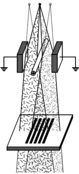
The electron-optical bisprism [10] consists of a positively or negatively charged filament of less than 1µm in diam-eter, stretched between earthed electrodes located on both sides of it (Fig. 2). The incoming wavefront is divided into two parts when passing the biprism wire. If the filament is charged positively (negatively) they are deflected towards (apart from) each other. The deflection angle of the elec-tron waves passing the field distribution in the vicinity of the filament (it is equivalent there to the field of a cylindri-cal capacitator) is the same for all paths irrespective of their distance from the center of the filament. In analogy to the Fresnel biprism in light optics, the divided wavefront seems to emerge from two virtual sources (dotted paths in Fig. 2). Since field-emitted electrons meet the spatial and temporal coherence conditions, interference fringes are formed in the region of superposition of the wavefronts. They are magni-fied electron-optically (not shown in Fig. 2) and observed on the screen of a channel plate image intensifier.
Figure 2. Scheme of the electron-optical biprism.
The first electron biprism interferometers and also to-day’s electron holography instruments are modified
elec-tron biprism interferometer was developed [11]. In this type of interferometer, the electron-optical components are much smaller in dimension and in mass; they are, in general, of cylindrical shape with a diameter of(28±0.01)mm and are tightly screwed on two high-precision ceramic rods by means of braces. The arrangement is very rigid. Con-sequently, its mechanical eigenfrequency is raised to val-ues far above the frequencies of floor vibrations and can-not be excited by these. Due to the construction principle, all elements are prealigned to the optical axis. Mechani-cal feedthroughs for alignment are not required. Fine align-ment is achieved by electrostatic deflection elealign-ments and electromagnetic coils (with the latter, the image can be ro-tated). The whole interferometer can easily be surrounded by a highly effective tube of mu-metal with a shielding fac-tor exceeding 5000. As a result, magnetic AC fields which would wash out the interference fringes are suppressed. As an electron source, a cold field emission gun is used necessi-tating an ultra-high vacuum environment. The electrons are accelerated by the field emission extraction voltage to their final energy in the range of 500 - 2500 eV in a simple diode system consisting of a tungsten tip (cathode) on negative and an anode on earth potential.
This type of ruggedized electron interferometer has suc-cessfully been employed, e.g., to demonstrate the Sagnac effect with electrons [12, 13], to measure coherence length and energy spectra of electrons by means of Fourier spec-troscopy [14, 15] using a Wien filter [16, 17], to prove elec-tron antibunching [18], and to realize a biprism interferom-eter for He+ions [19] with their – compared to electrons – extremely short wavelengths in the sub-pm range.
3
Scheme of the decoherence
experi-ment and experiexperi-mental set-up
induced charge x
z
Figure 3. Sketch of the decoherence experiment. The two different paths of the electron over the resistive plate induce different disturbances (shaded regions) in the electron and phonon gas inside the plate. In the primary interference plane (rhs), interference fringes show less and less contrast the closer they are to the shadow of the plate.
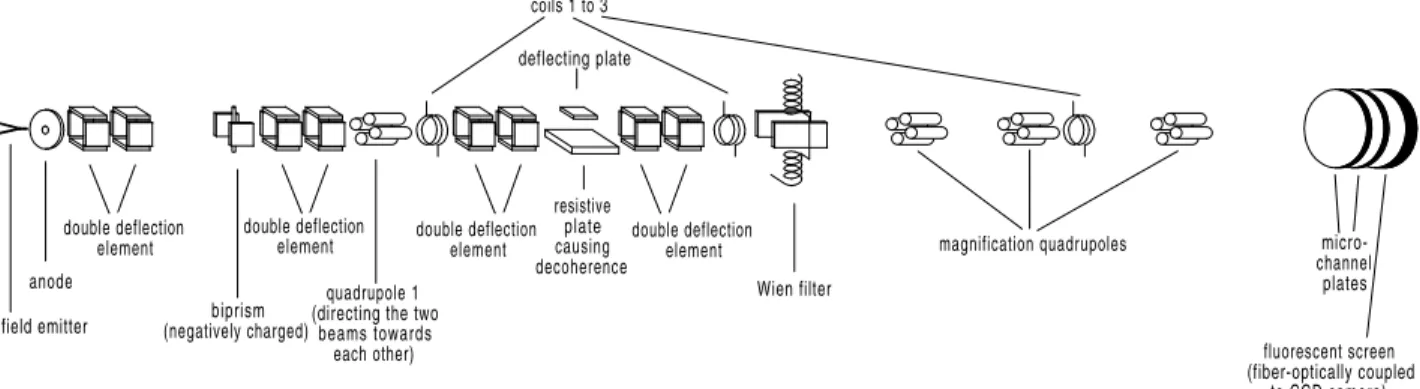
double deflection element double deflection
element
quadrupole 1 (directing the two
beams towards each other) double deflection
element
anode
field emitter (negatively charged)biprism
double deflection element
resistive plate causing decoherence deflecting plate coils 1 to 3
magnification quadrupoles
Wien filter
fluorescent screen (fiber-optically coupled
to CCD camera) micro-channel plates
Figure 4. Schematical set-up of the compact rigid interferometer used in the decoherence experiment. (A corresponding photograph of the experiment is available from the authors upon request.)
As already mentioned, this gives rise to an interaction between the free electron and the plate: The electron in-duces a charge inside the plate, and this induced charge will move along with the beam electron. Therefore we get an electric current inside the plate, and the current encounters ohmic resistance. This leads to dissipation, there is Joule heating which quantum mechanically means that the state of the electron and phonon gas inside the plate is disturbed. The disturbance isdifferentfor the two parts of the beam. This can equivalently be interpreted either in terms of the availability of which-path information or in terms of en-tanglementof beam electron and plate. As the disturbance is irreversible, a record of the electron’s pathremains. So when the two parts of the beam are recombined, they are not fully capable of interference, and contrast of the interference fringes is reduced.
The interference pattern formed in the primary interfer-ence plane (where the two beams merge) is enlarged by elec-trostatic magnification quadrupoles. Its intensity is then am-plified by a dual-stage channel plate image intensifier, trans-ferred to a CCD camera by tapered fiber optics, and evalu-ated by an image processing system.
4
Theoretical considerations
Before the interaction of the beam electron with the elec-tron and phonon gas inside the resistive plate, the state of the electron is a coherent superposition of the two parts of
the beam,
|ψ= (|l+|r)/√2
where|lresp.|rdenote the ‘left’ resp. ‘right’ part of the beam. The state of the electron and phonon gas before the interaction is certainly a mixed state. But for any of the pure states|φ0into which this mixed state can be decom-posed into, the interaction produces an entangled state of beam electron and electron & phonon gas:
(|l+|r)/√2⊗ |φ0 →(|l ⊗ |L+|r ⊗ |R)/
√
2
where|Land|Rare the states of the electron & phonon gas corresponding to the two parts of the beam electron.
The strength of the interaction and therefore the magni-tude of the disturbance of the electron & phonon gas cer-tainly increases with decreasing heightzof the beams over the plate. Furthermore, the ‘difference’ between the two dis-turbed states of the electron & phonon gas which correspond to the two different parts of the beam electron will increase with increasing lateral separation∆xbetween the beams. From these simple considerations it is already clear that the absolute value of the scalar product L|R increases with increasing∆xand with decreasingz. If we measure an ob-servable affecting only the beam electron, interference (be-tween states|land|r) is the more suppressed the smaller
(ebeing the elementary charge,ρthe resistivity of the plate, andv the velocity of the beam electron), and the relation between decoherence timeτdand relaxation timeτr=
v
|v˙|,
τd=
2
mkBT(∆x)2
τr
(m denoting the free electron mass, kB the Boltzmann constant, and T temperature), taken from a linear model [20, 21, 22, 23] lead to a decoherence time
τd=
4h2z3
πe2k
BT ρ(∆x)2
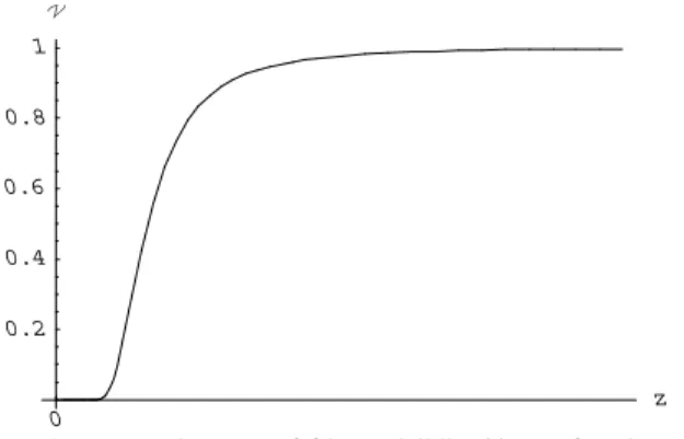
which should be valid ifρand∆xare not too large. The contrast (visibility) of the electron interference fringes will then be
V= exp
−tflight τd
wheretflightis the time of flight of the beam electron over the plate. The expected course of fringe visibility as a func-tion of heightzis shown in Fig. 5.
0
z 0.2
0.4 0.6 0.8 1 =
Figure 5. Expected course of fringe visiblityVas a function of heightzof beams over the plate.
There are other mechanisms which can also cause de-coherence in this experiment: Vacuum fluctuations near a (perfect) conductor [24, 25] and emission of bremsstrahlung even in free space [26]. But both of these effects are much smaller than decoherence due to dissipation to the induced current in a poor conductor.
Stimulated by our experiment, Levinson [27] calculated the change in contrast due to vacuum fluctuations in the presence of dissipation.
5
Results and discussion
Figure 6 shows the interference fringes for electrons of 1.665keV of energy in heights above the resistive plate
in visibility with decreasing heightz. Also observable is the decrease in contrast with increasing lateral separation∆x. This decrease as a function of∆xis not only caused by de-coherence, but also by the fact that for smaller fringe spac-ing contrast is reduced due to lateral coherence. Quantitative analysis of the data is in progress and will be able to correct for the effect of lateral coherence by comparison with fringe contrast far away from the plate. It will also allow to com-pare the experimental results and the theoretical predictions of Anglin and Zurek [1] and of Levinson [27] and might give evidence if decoherence saturates [1] at a certain lateral separation∆x.
The pictures in Fig. 6 are images from the quantum-classical border showing directly the transition from the quantum regime (for large heightsz, small lateral separa-tions∆x) where there is full interference – i.e. an electron behaves totally like a wave – to the classical regime (for smallz, large∆x) where (almost) full which-path informa-tion is available in principle – and an electron therefore be-haves like a particle with a definite trajectory.
In order to be sure that the observed decrease in visibil-ity is really caused by decoherence, other contrast-reducing effects had to be excluded. One of these effects might be that the longitudinal coherence condition is not fulfilled, i.e. that there is a wave packet shift – accumulated, e.g., in the elec-trostatic deflection elements where the two parts of the beam travel on different electric potential with different group ve-locities. Apart from the fact that one would expect this wave packet shift to be the same in all heights over the plate, one can eliminate it by using a Wien filter (crossed-field ana-lyzer) [16, 17]. The Wien filter consists of an electric and a magnetic field, both being perpendicular to the optical axis and to each other (Fig. 7 a, rhs). When the matching condi-tionE =vBbetween electric fieldEand magnetic fieldB
is fulfilled for the main velocity componentvof the beam, there is neither a force on a beam electron (if it travels on the optical axis) nor does the Wien filter introduce a phase shift, but there is a wave packet shift due to the different elec-tric potential for the two paths. By varying the excitation of the matched Wien filter, one can change the longitudinal distance between the interfering wave packets thus altering fringe visibility (Fig. 7 b). The maximum attainable contrast is the one corresponding to no resultant wave packet shift. Experimentally it was found that the contrast shown in Fig. 6 cannot be enhanced in any height by varying the Wien fil-ter’s excitation, so the loss of contrast in these pictures in not due to a wave packet shift.
a) b) c)
Figure 6. Decoherence as a function of heightzof the beams over the plate for increasing lateral separations∆xof the beams. The bottom
of all pictures corresponds to a distancezof∼ 15µm from the plate, the top to∼ 40µm. The lateral separation∆xis∼ 11µm in
a),∼14µm in b), and∼18µm in c). Both the increase of contrast (corresponding to a decrease in decoherence) fromz ≈ 15µm to
z≈40µm and the decrease of contrast from a) to c) is clearly visible in the micrographs. The latter is caused by increasing decoherence
and additionally by decreasing angular coherence with a larger lateral separation. The triangular structure which is visible near the bottom in all micrographs is due to charging of a dust particle on thebiprism filament.
a) S1 S S2
biprism
Wien filter
β
S1 S S2
biprism
B⊥E
Wien filter
β
b)
Figure 7. a) Electron biprism interferometer with Wien filter switched off (left) and Wien filter being excited (right): The wave packet shift exceeding the coherence length leads to the disappearance of the interference fringes. b) Restoration of contrast by a Wien filter: The longitudinal shift of the wave packets caused by electrostatic deflection elements (top) can be compensated (middle) and overcompensated (bottom) with the Wien filter [17]. The 11 micrographs correspond to 11 different excitations of the Wien filter, increasing from top to bottom.
Like for the case of a wave packet shift, all other con-ceivable effects which might reduce fringe visibility could be excluded as explanation of the loss of contrast observed in Fig. 6, leaving only decoherence as the reason.
Compared to other experiments on decoherence [30], the present one has several advantages: It is conceptually very simple, it realizes an actually ohmic environment (as it was supposed in the first theoretical treatments of decoherence), the quantum object is a single free elementary particle (no
inner degrees of freedom are involved – due to the absence of magnetic fields, spin is irrelevant in the present exper-iment), the interaction with the environment is due to the electric field of a charge (thus giving us an idea why the charge superselection rule is so powerful), and we get real ‘pictures’ of the transition from quantum to classical.
Acknowledgements
fi-[1] J.R. Anglin, W.H. Zurek, in: Dark Matter in Cosmology – Quantum Measurements – Experimental Gravitation : Proc. XXXIst Rencontres de Moriond, ed. by R. Ansari, Y. Giraud-H´eraud, J. Trˆan Thanh Vˆan (Editions Frontieres, Gif-sur-Yvette, 1996), p. 263. quant-ph/9611049 v2.
J.R. Anglin, J.P. Paz, and W.H. Zurek, Phys. Rev. A55, 4041 (1997).
[2] E. Schr¨odinger, Naturwissenschaften14, 664 (1926).
[3] W. Heisenberg, Z. Phys.43, 172 (1927).
[4] N. Bohr, Nature (London)121, 580 (1928).
[5] E. Schr¨odinger, Naturwissenschaften23, 807 (1935).
[6] H.D. Zeh, Found. Phys.1, 69 (1970).
[7] W.H. Zurek, Phys. Rev. D24, 1516 (1981).
[8] E. Jooset al., Decoherence and the Appearance of a Classical World in Quantum Theory, (Springer, Berlin, 2003).
[9] W.H. Zurek, Rev. Mod. Phys.75, 715 (2003).
[10] G. M¨ollenstedt, H. D¨uker, Z. Phys.145, 377 (1956).
[11] F. Hasselbach, Z. Phys. B71, 443 (1988).
[12] F. Hasselbach, M. Nicklaus, Phys. Rev. A48, 143 (1993).
[13] R. Neutze, F. Hasselbach, Phys. Rev. A58, 557 (1998).
[14] F. Hasselbach, A. Sch¨afer, and H. Wachendorfer, Nucl. In-strum. Methods Phys. Res., Sect. A363, 232 (1995).
[15] P. Sonnentag, H. Kiesel, and F. Hasselbach, Micron31, 451 (2000).
[18] H. Kiesel, A. Renz, and F. Hasselbach, Nature (London)418, 392 (2002).
[19] F. Hasselbach, U. Maier, in: Quantum Coherence and Deco-herence : Proc. ISQM-Tokyo ’98, ed. by Y.A. Ono, K. Fu-jikawa (Elsevier, Amsterdam, 1999), p. 299.
[20] W.H. Zurek, in: Frontiers of Nonequilibrium Statistical Physics, ed. by G.T. Moore, M.O. Scully (Plenum, New York, 1986), p. 145.
[21] J.P. Paz, S. Habib, and W.H. Zurek, Phys. Rev. D47, 488 (1993).
[22] E. Joos, in: [8], Chapter 3.
[23] H.-P. Breuer, F. Petruccione, The Theory of Open Quantum Systems (Oxford Univ. Press, Oxford, 2002), Chapter 4.3.
[24] L.H. Ford, Phys. Rev. D47, 5571 (1993).
[25] F.D. Mazzitelli, J.P. Paz, and A. Villanueva, Phys. Rev. A68, 062106 (2003).
[26] H.-P. Breuer, F. Petruccione, Phys. Rev. A63, 032102 (2001).
[27] Y. Levinson, J. Phys. A37, 3003 (2004).
[28] F. Hasselbach, H. Kiesel, P. Sonnentag, in: Decoherence: Theoretical, Experimental, and Conceptual Problems, ed. by P. Blanchardet al.(Springer, Berlin, 2000), p. 201.
[29] C. Kiefer, in: [8], Chapter 4.
![Figure 1. Sketch of the interference experiment on decoherence proposed by Anglin and Zurek [1].](https://thumb-eu.123doks.com/thumbv2/123dok_br/18981244.457101/1.918.509.787.661.784/figure-sketch-interference-experiment-decoherence-proposed-anglin-zurek.webp)