Volume 2012, Article ID 276906,13pages doi:10.1155/2012/276906
Research Article
A Rotor Flux and Speed Observer for Sensorless Single-Phase
Induction Motor Applications
Massimo Caruso,
1Vittorio Cecconi,
1Antonino O. Di Tommaso,
1and Ronilson Rocha
21Department of Electrical, Electronics and Telecommunications Engineering, University of Palermo, Vialle delle Scienze, Edificio 9,
90128 Palermo, Italy
2Department of Control and Automation Engineering, School of Mines, Federal University of Ouro Preto, Campus Morro do Cruzeiro,
35400-000 Ouro Preto, MG, Brazil
Correspondence should be addressed to Ronilson Rocha,[email protected]
Received 6 October 2011; Revised 5 January 2012; Accepted 26 January 2012
Academic Editor: Hyeong Joon Ahn
Copyright © 2012 Massimo Caruso et al. This is an open access article distributed under the Creative Commons Attribution License, which permits unrestricted use, distribution, and reproduction in any medium, provided the original work is properly cited.
It is usual to find single-phase induction motor (SPIM) in several house, office, shopping, farm, and industry applications, which are become each time more sophisticated and requiring the development of efficient alternatives to improve the operational performance of this machine. Although the rotor flux and rotational speed are essential variables in order to optimize the operation of a SPIM, the use of conventional sensors to measure them is not a viable option. Thus, the adoption of sensorless strategies is the more reasonable proposal for these cases. This paper presents a rotor flux and rotational speed observer for sensorless applications involving SPIMs. Computer simulations and the experimental results are used to verify the performance of the proposed observer.
1. Introduction
The single-phase induction motor (SPIM) has a very robust design and can be mass produced with relatively low cost. Traditionally used in fractional and subfractional horsepow-er applications, it is usual to find this motor in sevhorsepow-eral house,
office, shopping, farm, and industry appliances such as air
conditioning systems, mixers, washers, blowers, dryers, fans, refrigerators, vacuum cleaners, compressors, pumps, and so forth. Due to introduction of low-cost static power convert-ers and the development of more sophisticated appliances, the traditional SPIM applications have required the
develop-ment of efficient alternatives to improve the performance of
this machine.
The SPIM is basically constituted by a squirrel-cage rotor
and two stator windings displaced 90◦ in space, known as
main and auxiliary windings. This machine is usually
unbal-anced, and its windings present different impedances. When
the main winding is fed by a single-phase source, the pro-duced magnetic field is pulsating and stationary, and a starting torque is not developed. To start a SPIM, the auxilia-ry winding must emulate a second phase. Although the auxil-iary winding is often disconnected by a centrifugal switch
when the SPIM rotor reaches 60% to 80% of rated speed, it can be maintained at running operation in order to provide a higher and less pulsating torque. In general, a series capacitor is connected with the auxiliary winding in order to improve the starting and the SPIM performance.
Many proposals for the better performance of a SPIM are based in the use of an electronically switched series capacitor in the auxiliary winding, which can be controlled to improve
the machine performance at different operating conditions
[1–4]. The variable speed drives are also proposed in
sever-al SPIM applications in order to provide energy savings and
torque improvement [5–13]. Although the magnetic flux
and/or rotational speed of this machine are essential variables in order to optimize the performance of a SPIM, the use of sensors to measure them cannot be justified in fractional and low-cost SPIM applications since then implies in more
electronics, higher cost, lower reliability, assembling diffi
-culties, and the increase in weight, size, and electrical suscep-tibility. Considering these problems, the adoption of a sen-sorless strategy is a more reasonable option for high-per-formance SPIM applications, where the magnetic flux and/or rotational speed are estimated from stator voltage and
^ λsα isα vsα − +
α-Compensator α-Model
^ uα ^isα ^ λsβ isβ vsβ − +
β-Compensator ^uβ β-Model
^
isβ
Figure1:α- andβ-Flux observer structures.
isα − − − − + + + +
+ u^α
^
ωr^λrβ
^
λrα
1
sτα+1 kα
s+zα
s rα L Lmα 1 N PI compensator Low-pass filter
LsαLrα−L2mα
Lmα 1 s 1 s Rrα Lrα sτα
sτα+ 1
RrαLmα
Lrα
High-pass filter
RsαL2rα+RrαL2mα
LrαLmα
^isα
vsα isβ vsβ − − − − − + + + + ^ uβ ^
ωrλ^rα
^
λrβ
1
sτβ+1 kβ
s+zβ
s Lrβ Lmβ N PI compensator Low-pass filter
LsβLrβ−L2mβ
Lmβ 1 s 1 s Rrβ Lrβ sτβ
sτβ+ 1
RrβLmβ
Lrβ
High-pass filter
RsβL2rβ+RrβL2mβ
LrβLmβ
^
isβ
Figure2: Block diagram ofα- andβ-flux observers.
This paper presents an original proposal of a rotor flux observer for SPIM, from which the rotor speed of this motor can be estimated. This observer can be used in applications involving SPIMs that require the estimation of rotor flux and/or rotor speed, such as optimization strategies, sensor-less vector control of the machine based on the philosophy of the direct flux orientation, and so forth. Two half flux observers are designed using the stationary reference frame SPIM model. From these half flux observers, data are obtained to estimate the rotor speed of the SPIM. The per-formance of the proposed observer is satisfactorily demon-strated from computer simulations and experimental tests considering two situations: a step variation in the stator fre-quency of the no load SPIM and the application of mechani-cal load to SPIM shaft.
2. Flux Observer
Traditionally, the dynamic model of a SPIM is described
con-sidering a stationary reference frameα-βfixed in the stator,
whereαandβdenote the auxiliary and main windings
re-spectively [18]. If the stator currentsisand the rotor fluxλr
vectors are admitted as the state variables, this dynamic
mod-el can be written as follows [17]:
(i)α-model
˙
isα=
Lmα Lσα
Lrα
Lmαvsα+
Rrα
Lrαλrα−
Rφα
LrαLmαisα+
uα N
,
˙
λrα= −
Rrα
Lrα(λrα−Lmαisα)−
uα
N,
(1)
(ii)β-model
˙
isβ=
Lmβ Lσβ
Lrβ
Lmβvsβ+
Rrβ
Lrβλrβ−
Rφβ
LrβLmβisβ−Nuβ
,
˙
λrβ= −Rrβ
Lrβ
λrβ−Lmβisβ
+Nuβ,
isβ isβ
isα isα
vsβ vsβ
^
ωrλ^rβ
^
ωr^λrα
^
λrα
^
λrβ
Envelope detector
Envelope detector
Envelope detector
Envelope detector
β-Flux observer
α-Flux observer
vsα vsα
^
ωrβ ω^rα
^
λrα|peak
^
λrβ|peak
^
ωrλ^rα|peak
^
ωr^λrβ|peak
∗
/
∗
/
Figure3: Speed estimation using flux observers and envelope detectors.
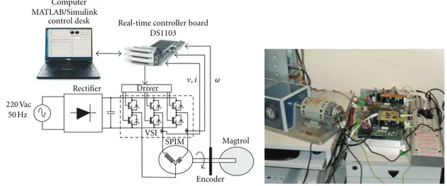
Computer MATLAB/Simulink
control desk
220 Vac 50 Hz
Rectifier Driver v
,i
SPIM VSI
ω
Magtrol
Encoder Real-time controller board
DS1103
Figure4: SPIM test bench.
Table1: SPIM data.
Rated values
Voltage 110 V
Frequency 50/60 Hz
Main winding current 2.3 A
Speed 2700 RPM
No. of poles 2
Power 0.25 HP (180 W)
Main winding (β) Auxiliary winding (α)
Rsβ 5.2Ω Rsα 29Ω
Rrβ 9.4Ω Rrα 35.9Ω
Lmβ 0.3 H Lmα 0.45 H
Lsβ 0.3068 H Lsα 0.55 H
Lrβ 0.3068 H Lrα 0.55 H
N=Nβ/Nα 0.67
wherevs=stator voltage,ωr=rotational speed,uα=ωrλrβ,
uβ =ωrλrα,R =resistance,L=winding inductance,Lm =
mutual inductance,Rφ =RsL2r+RrLm2,Lσ =LsLr−L2m, and
N =transformer ratio between both stator windings. The
subscriptssandrare related, respectively, to stator and rotor
variables and parameters.
Table2: Electrical characteristics of the IGBT power converter.
Input voltage (single phase) 230 VCA
Motor supply rail 310 VDC
Output power peak 6.5 kW
Phase current peak (crest) 30 A Phase current cont. 21 A(RMS) Switching frequency 5 to 20 kHz
Shunt power peak 3200 W
In order to obtain the convergence of the observed vari-ables to its real value in conventional state observers, a cor-rectional term is usually inserted in the system model to reduce the error between the measurable variables and their respective estimated values. If this principle is applied to ob-serve the rotor fluxes of a SPIM, the resulting obob-server is
non-linear, since the termsuαanduβconsist in the product of two
state variables of the system. However, if these nonlinear
termsuαanduβof SPIM model are considered to correct the
observation error, the flux observer can be decoupled in two linear and independent closed-loop systems as shown in
4.8 5 5.2 5.4 5.6 5.8 6 6.2 6.4 6.6
−2
−1.5
−1
−0.5
0 0.5 1 1.5 2
Time (s)
A
uxiliar
y cur
re
nt (A)
(a)
5.6 5.61 5.62 5.63 5.64 5.65 5.66 5.67 5.68 5.69 5.7
−2
−1.5
−1
−0.5
0 0.5 1 1.5 2
Time (s)
A
uxiliar
y cur
re
nt (A)
(b)
4.8 5 5.2 5.4 5.6 5.8 6 6.2 6.4 6.6
−10
−8
−6
−4
−2
0 2 4 6 8 10
Time (s)
M
ain cur
re
nt (A)
True Estimated
(c)
5.6 5.61 5.62 5.63 5.64 5.65 5.66 5.67 5.68 5.69 5.7
−10
−8
−6
−4
−2
0 2 4 6 8 10
Time (s)
M
ain cur
re
nt (A)
True Estimated
(d)
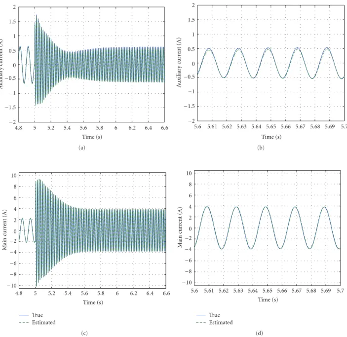
Figure5: Stator currents of the no-load SPIM and their estimated values during a step variation from 10 Hz to 50 Hz in the stator frequency
(computational simulation): (a) auxiliary windingisα, (b) details ofisα, (c) main windingisβ, (d) details ofisβ.
rotor flux observer is the possibility to evaluate the rotor speed of the SPIM, as will be seen in the next section.
Considering only the structure ofβ-flux observer shown
inFigure 1, the open-loop transfer function betweenisβand
uβadmittingvsβas system disturbance is given by
Isβ(s)
Uβ(s)=
−sNLmβ
s2Lσβ+sRσβ+RsβRrβ, (3)
whereRσβ = RrβLsβ+RsβLrβ. This transfer function has a
zero in the origin and two real poles. This zero provides a de-rivative action, which does not contribute to reduce the cur-rent error. Furthermore, this derivative action increases the
observer sensitive to noises and disturbances. In order to
prevent the effects of derivative action, a PI structure is
con-sidered forβ-compensator:
Uβ(s)
Isβ(s)−Isβ(s)
=kβs+zβ
s , (4)
where the pure integrator ofβ-compensator eliminates the
derivative action ofβ-model. The zerozβof the
β-compensa-tor can be chosen to cancel the slowest pole of the open-loop
transfer function of (3). Since the PI compensator and the
−0.6 −0.4 −0.2 0 0.2 0.4 0.6
−0.6
−0.4
−0.2
0 0.2 0.4 0.6
α-Rotor flux (Wb)
β
-R
ot
or flux (
Wb)
True Estimated Error
(a)
−0.6 −0.4 −0.2 0 0.2 0.4 0.6
−0.6
−0.4
−0.2
0 0.2 0.4 0.6
α -Rotor flux (Wb)
β
-R
ot
or flux (
Wb)
True Estimated Error
(b)
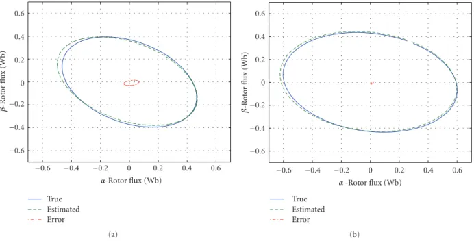
Figure6: Phase portraitλrα×λrβof the vector rotor flux of no-load SPIM (computational simulation): (a) 10 Hz, (b) 50 Hz.
4.8 5 5.2 5.4 5.6 5.8 6 6.2 6.4 6.6
0 50 100 150 200 250 300 350 400
Time (s)
R
o
to
r speed (r
ad/s)
True
α-Estimated
β-Estimated
(a)
4.8 5 5.2 5.4 5.6 5.8 6 6.2 6.4 6.6
0 50 100 150 200 250 300 350 400
Time (s)
R
o
to
r speed (r
ad/s)
True
α-Estimated
β-Estimated
(b)
Figure7: Rotor speedωrof the SPIM and its estimationsωrαandωrβduring steps in the frequency stator (computational simulation): (a)
from 10 Hz to 50 Hz, (b) from 50 Hz to 10 Hz.
used in order to verify the stability of the proposed struc-ture for rotor flux observation. The proposed design of the PI compensator imposes a pole-zero cancellation in the
open-loop transfer functionIsβ/(Isβ−Isβ), assuring that the slope
of the amplitude diagram will be always−20 db/dec and the
phase angle is always smaller than 135◦ in the cross-over
frequency. Thus, the proposed flux observer will be always
stable in these circumstances independently of the gainkβ.
This compensator provides an effective proportional action
and, consequently, an offset error will always be present in
the observation ofβ-flux. The performance of this structure
is determined by the gainkβ, which can be chosen in order to
4.8 5 5.2 5.4 5.6 5.8 6 6.2 6.4 6.6
−0.8
−0.6
−0.4
−0.2
0 0.2 0.4 0.6 0.8
Time (s)
A
uxiliar
y cur
re
nt (A)
(a)
5.6 5.61 5.62 5.63 5.64 5.65 5.66 5.67 5.68 5.69 5.7
−0.8
−0.6
−0.4
−0.2
0 0.2 0.4 0.6 0.8
Time (s)
A
uxiliar
y cur
re
nt (A)
(b)
4.8 5 5.2 5.4 5.6 5.8 6 6.2 6.4 6.6
−6
−4
−2
0 2 4 6
Time (s)
M
ain cur
re
nt (A)
True Estimated
(c)
5.6 5.61 5.62 5.63 5.64 5.65 5.66 5.67 5.68 5.69 5.7
−6
−4
−2
0 2 4 6
Time (s)
M
ain cur
re
nt (A)
True Estimated
(d)
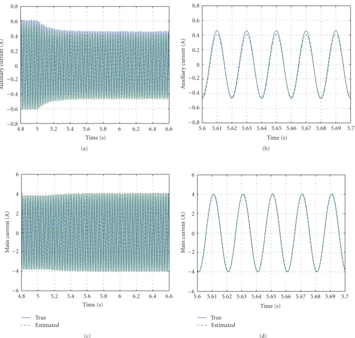
Figure8: Stator currents of the SPIM and their estimated values for 50 Hz during a load step (computational simulation): (a) auxiliary
windingisα, (b) details ofisα, (c) main windingisβ, (d) details ofisβ.
Considering the close-loopβ-observer with a PI
compen-sator, the transfer function between the estimated rotor flux
λrβand the measurementisβis given by
Λrβ(s)
Isβ(s) = −
sNkβ+Nkβzβ
s
× sLσβ+RsβLrβ
s2Lσβ+sRσβ+NkβLmβ+RsβRrβ+NkβzβLmβ,
(5)
where it is observed that the PI compensator introduces a pure integrator in the path of the estimated flux. This fact can compromise the performance of the proposed observer, since
any DC offset in the current sensors will be continuously
in-tegrated until the saturation of the integrators. In order to prevent this problem, a first-order high-pass filter with a very
low cut-off frequency (around Hz) must be inserted in
the path of the estimated flux to cancel the effects of the
pure integrator introduced by PI compensator. Although this solution can deteriorate the dynamical performance of the proposed flux observer at very low rotor speed, it is satisfac-tory for the most of SPIM applications which usually do not
work in this speed range. In order to reduce the effect of
measurement noises in the observer performance, a
first-or-der low-pass filter with an adequate cut-offfrequency could
−0.6 −0.4 −0.2 0 0.2 0.4 0.6
−0.6
−0.4
−0.2
0 0.2 0.4 0.6
α-Rotor flux (Wb)
β
-R
ot
or flux (
Wb)
True Estimated Error
Figure9: Phase portraitλrα×λrβof rotor flux for 50 Hz considering the loaded SPIM (computational simulation).
4.8 5 5.2 5.4 5.6 5.8 6 6.2 6.4 6.6
290 295 300 305 310 315 320 325 330
Time (s)
R
o
to
r speed (r
ad/s)
True
α-Estimated
β-Estimated
Figure10: Rotor speedωrand its estimationsωrαandωrβfor 50 Hz during the application of a load step (computational simulation).
The design of close-loopα-flux observer is analogous to
close-loopβ-flux observer. The complete block diagram of
the proposed flux observer is presented in theFigure 2. The
basic difference between both observers is the form as the
error signal must be computed, since the close-loopβ-flux
observer presents a reverse action.
3. Rotor Speed Estimation
If the observation of the rotor fluxes is satisfactory, an
estima-tive of the rotor speedωr can be obtained from the proposed
flux observers for sensorless applications. Since the outputs
of the PI compensators correspond to nonlinear terms,uα=
ωrλrβanduβ =ωr λrα,ωr can be estimated dividinguα byλrβ
oruβ byλrα. Sinceλrαandλrβare AC values, the computation
ofωr is subject to a singularity due to zero division. In order
to avoid this problem, the solution adopted in this work is
only to computeωr using the peak values of the signalsuα
(oruβ) andλrβ(orλrα), which occur simultaneously and can
be captured using envelope detectors as shown inFigure 3.
4. Experimental Test Bench
The experimental apparatus shown inFigure 4is used to
ver-ify the performance of the proposed rotor flux/speed
0 0.2 0.4 0.6 0.8 1 1.2 1.4 1.6 0
0.5 1 1.5
Time (s)
A
uxiliar
y cur
re
nt (A)
−1.5
−0.2
−1
−0.5
(a)
0.6 0.61 0.62 0.63 0.64 0.65 0.66 0.67 0.68 0.69 0.7 0
0.5 1 1.5
Time (s)
A
uxiliar
y cur
re
nt (A)
−0.5
−1.5
−1
(b)
0 0.2 0.4 0.6 0.8 1 1.2 1.4 1.6
0 2 4 6 8
Time (s)
M
ain cur
re
nt (A)
Measured Estimated
−0.2
−8
−6
−4
−2
(c)
0.6 0.61 0.62 0.63 0.64 0.65 0.66 0.67 0.68 0.69 0.7 0
2 4 6 8
Time (s)
M
ain cur
re
nt (A)
Measured Estimated
−8
−6
−4
−2
(d)
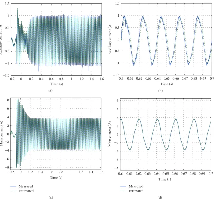
Figure11: Measured and estimated stator currents of the SPIM during the step from 10 Hz to 50 Hz in the frequency stator (experimental
results): (a) auxiliary windingisα, (b) details ofisαat 50 Hz, (c) main windingisβ, (d) details ofisβat 50 Hz.
where the parameters of the equivalent circuit are evalu-ated from the experimental DC, locked rotor, and no-load
tests [19]. An optical incremental encoder (SUMTAK
Corpo-ration, type LDA-001-1000 CE, 1024 pulses per revolution) is coupled to SPIM shaft in order to measure the rotational speed and compare it to its estimative. A magnetic powder brake Magtrol emulates the mechanical load. The SPIM windings are fed by two quadrature AC voltages with con-stant V/f ratio generated by an IGBT-based three-leg voltage source inverter (VSI) whose electrical characteristics are
summarized inTable 2. The use of a three-leg inverter
pre-sents many advantages over a two-leg topology such as gener-ate a zero voltage vector, avoid the circulation of an AC cur-rent in the DC link capacitor, and improve the output voltage
quality in terms of harmonic distortion [6,7,12,13]. The
in-tegrated sensors to VSI are used to measure the currents of
the main and auxiliary stator windings. The experimental implementation of the proposed observer is realized using a dSPACE DS1103 controller board, which allows a rapid
real-time prototyping [20,21]. Since this hardware is linked to
0 0.2 0.4 0.6 0.8 1 1.2 1.4 1.6 0
50 100 150 200 250 300 350
Time (s)
R
o
to
r speed (r
ad/s)
Measured Estimated
−0.2
(a)
−00.2 0 0.2 0.4 0.6 0.8 1 1.2 1.4 1.6
50 100 150 200 250 300 350
Time (s)
R
o
to
r speed (r
ad/s)
Measured Estimated
(b)
Figure12: Estimated and measured rotor speedωr of the SPIM during the step in the frequency stator (experimental results): (a) from
10 Hz to 50 Hz, (b) from 50 Hz to 10 Hz.
−0.2 0 0.2 0.4 0.6 0.8 1 1.2 1.4 1.6
−0.8
−0.6
−0.4
−0.2
0 0.2 0.4 0.6 0.8
Time (s)
R
ot
o
r flux (
Wb)
α-Axis
β-Axis
(a)
0.6 0.61 0.62 0.63 0.64 0.65 0.66 0.67 0.68 0.69 0.7
−0.8
−0.6
−0.4
−0.2
0 0.2 0.4 0.6 0.8
R
ot
o
r flux (
Wb)
Time (s)
α-Axis
β-Axis
(b)
Figure13: Estimated rotor fluxesλrof the SPIM during the step from 10 to 50 Hz in the frequency stator (experimental results): (a) estimated
rotor fluxes, (b) details of the estimated rotor fluxes at 50 Hz.
instrument panel that enables the monitoring of measured and estimated variables and the adjustment of system values.
5. Observer Performance
5.1. Simulation Results. Considering the experimental appa-ratus presented in the last section, a computer simulation was done using MATLAB/simulink in order to verify the per-formance of the proposed observer. In the first test, the
stator frequency of the no-load SPIM is varied from 10 to 50 Hz and from 50 Hz to 10 Hz. The stator currents of the
SPIM are shown inFigure 5. The auxiliary winding current
isα is 0.40Arms at 10 Hz, which is practically maintained
at 50 Hz. The main winding current isβ is 1.50Arms, and
increases to 2.70Arms at 50 Hz. Although a delay is noted
in the estimation, the proposed observer presents a good accuracy to estimate the stator currents of the SPIM with an error smaller than 8%. The phase diagrams of the vector flux
−0.2 0 0.2 0.4 0.6 0.8 1 1.2 1.4 1.6
−1.5
−1
−0.5
0 0.5 1 1.5
Time (s)
A
uxiliar
y cur
re
nt (A)
(a)
0.6 0.61 0.62 0.63 0.64 0.65 0.66 0.67 0.68 0.69 0.7 Time (s)
−1.5
−1
−0.5
0 0.5 1 1.5
A
uxiliar
y cur
re
nt (A)
(b)
−0.2 0 0.2 0.4 0.6 0.8 1 1.2 1.4 1.6
−6
−4
−2
0 2 4 6
Time (s)
M
ain cur
re
nt (A)
Measured Estimated
(c)
0.6 0.61 0.62 0.63 0.64 0.65 0.66 0.67 0.68 0.69 0.7
−6
−4
−2
0 2 4 6
Time (s)
M
ain cur
re
nt (A)
Measured Estimated
(d)
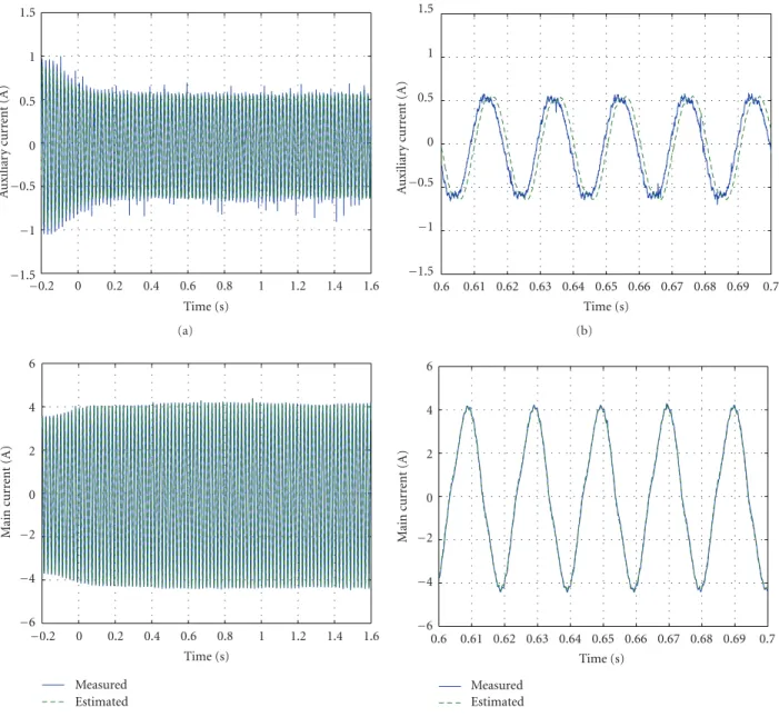
Figure14: Measured and estimated stator currents of the SPIM when the rated mechanical load is applied (experimental results): (a)
auxiliary windingisα, (b) details ofisα, (c) main windingisβ, (d) details ofisβ.
the maximum error∆λrin the flux estimation is smaller than
8% and it is observed when the SPIM operates at 10 Hz. This error in the flux estimative at lower frequencies can be justified by the presence of the high-pass filter in the observer structure, whose function is to prevent problems related to
DC offset in the current sensors. The acceleration and
decel-eration of the SPIM are shown in theFigure 7, where a good
agreement can be noted in steady state condition between the
speed estimativeωrα obtained fromλrαand the rotor speed of
the SPIMωr. Althoughωrβ obtained fromλrβalso has a good
agreement withωrat high frequencies, this speed estimative
presents an error at low frequencies which can be attributed to presence of the high-pass filter in the observer structure.
The dynamic response ofωrβ is more oscillatory thanωrα. It
is also observed that the estimated valuesωrα andωrβ present
a lag in relation toωr, which is caused principally by the
low-pass filters of the envelope detectors.
In the second simulated test, the rated mechanical load is applied to SPIM shaft when the a stator frequency is 50 Hz. In this simulated situation, the application of mechanical load
reduces the auxiliary winding currentisαto 0.30Arms while
the main winding currentisβis slightly increased to 2.80Arms
as presented inFigure 8. The error observed in the estimation
of both currents is lower than 6%. The phase diagram of the vector flux considering the loaded SPIM is presented in
Figure 9, where it can be verified that the error in the flux
estimations is smaller than 4%. Considering Figure 10, the
proposed observer provides accurate estimations for rotor
speedωr in this simulated situation, with little delay and an
−0.2 0 0.2 0.4 0.6 0.8 1 1.2 1.4 1.6
−1.5
−1
−0.5
0 0.5 1 1.5
Time (s)
A
uxiliar
y cur
re
nt (A)
(a)
0.6 0.61 0.62 0.63 0.64 0.65 0.66 0.67 0.68 0.69 0.7
−1.5
−1
−0.5 0 0.5 1 1.5
Time (s)
A
uxiliar
y cur
re
nt (A)
(b)
−0.2 0 0.2 0.4 0.6 0.8 1 1.2 1.4 1.6
−6
−4
−2
0 2 4 6
Time (s)
M
ain cur
re
nt (A)
Measured Estimated
(c)
0.6 0.61 0.62 0.63 0.64 0.65 0.66 0.67 0.68 0.69 0.7
−6
−4
−2
0 2 4 6
Time (s)
M
ain cur
re
nt (A)
Measured Estimated
(d)
Figure15: Measured and estimated currents of the SPIM when the rated mechanical load is removed (experimental results): (a) auxiliary
windingisα, (b) details ofisα, (c) main windingisβ, (d) details ofisβ.
5.2. Experimental Results. In order to acquire the electrical and mechanical measurements, the “trigger” function of the
virtual oscilloscope offered by the dSPACE system is used to
register an event occurrence, causing the registrations with negative value for time intervals before the trigger event.
The first experimental test consists of the application of a step variation from 10 to 50 Hz in the stator frequency of the no-load SPIM. Both time response of the auxiliary winding
currentisαand main winding currentisβobtained in this test
are shown inFigure 11, where it can be observed that the
estimated currents are very close to the measured values, demonstrating a good accuracy of the proposed observer to estimate the stator currents. It is observed a delay in the
esti-mation of the stator currents, which is negligible forisβ. The
SPIM speed response stepwise is reported inFigure 12, where
the estimated speedωrβ and the measured speedωr clearly
present a good agreement in steady-state condition in the experimental acceleration and deceleration of the SPIM. The delay in the estimation of the speed can be attributed to the presence of the low-pass filters in the envelope detectors.
Figure 13shows the estimated fluxesλrα andλrβ, which can be considered accurate since the proposed observer has ob-tained good estimations for stator currents and rotor speed in the acceleration and deceleration of the SPIM.
The second experimental test consists in to apply and re-move the rated mechanical load of the SPIM, which is operating with a stator frequency of 50 Hz. The auxiliary
winding currentisα is reduced while the main winding
cur-rent isβ increases with the load application, as shown in
Figure 14. The estimation error in the estimation of the stator currents disappears when the mechanical load is removed
−0.2 0 0.2 0.4 0.6 0.8 1 1.2 1.4 1.6 260
265 270 275 280 285 290 295 300 305 310
Time (s)
R
o
to
r speed (r
ad/s)
Measured Estimated
(a)
−0.2 0 0.2 0.4 0.6 0.8 1 1.2 1.4 1.6
260 265 270 275 280 285 290 295 300 305 310
Time (s)
R
o
to
r speed (r
ad/s)
Measured Estimated
(b)
Figure16: Measured and estimated rotor speedωr(experimental results): (a) when a mechanical load is applied to SPIM shaft, (b) when a
mechanical load is removed of the SPIM shaft.
current estimations of the proposed observer are accurate
and present a small delay, which is negligible forisβ. The ef-
fect of the mechanical load over the estimated speedωrβand
the measured speedωr is shown inFigure 16, where is
ob-served the presence of a little delay during the transient
be-havior and a small error between the estimated speedωrβ and
the measured speedωrin steady-state, which is acceptable for
the majority of the SPIM applications.
It is noted that the experimental results practically
repro-duce the computational simulations, whose differences can
be justified by the uncertainties in the parameter estimation of the SPIM, which are greatest for the auxiliary winding and mechanical parameters. The experiments and the simula-tions demonstrate that the estimasimula-tions of the stator currents and the rotor speed are satisfactory, indicating that the rotor flux estimation must be correct. Thus, the experimental performance of the proposed observer corroborates the com-putational simulations, demonstrating that it provides a satisfactory estimation for the rotor flux and the rotor speed of the SPIM with good accuracy within the usual frequency range considered for most SPIM application.
6. Conclusion
This paper presents the design, simulation, and implementa-tion of a rotor flux and speed observer for the development of sensorless applications involving SPIMs. This observer is based in two half flux observers, which are designed using the stationary reference frame SPIM model. From these half flux observers, data are obtained in order to estimate the rotor speed of the SPIM. The performance of the proposed observer is computationally and experimentally evaluated considering two situations: a step variation in the stator
fre-quency of the no-load SPIM and the application of mechani-cal load to SPIM shaft. The computational simulations and the experimental results present good agreement, demon-strating that the proposed observer provides satisfactory esti-mations of the rotor flux and rotor speed of the SPIM, with good accuracy within of the usual frequency range consid-ered for most SPIM applications. In this context, the observer presented in this paper consists in an interesting option to estimate the rotor flux and/or rotational speed for sensorless applications involving the control of variable speed drives and/or development of optimization strategies for SPIMs.
Acknowledgment
The authors gratefully thank SDESLab (Sustainable Develop-ment and Energy Savings Laboratory), University of Paler-mo, for the support given during the experimental tests, and the financial support of MIUR (Ministero dell’Istruzione dell’Universit´a e della Ricerca, Italy), CNPq (Conselho Na-cional de Desenvolvimento Cientifico e Tecnol ´ogico, Brazil), CAPES (Coordenac¸˜ao de Aperfeic¸oamento de Pessoal de Nivel Superior, Brazil), FAPEMIG (Fundac¸˜ao de Amparo a Pesquisa do Estado de Minas Gerais-Brazil) and Gorceix foundation (Brazil).
References
[1] T. A. Lettenmaier, D. W. Novotny, and T. A. Lipo, “Single-phase induction motor with an electronically controlled ca-pacitor,”IEEE Transactions on Industry Applications, vol. 27, no. 1, pp. 38–43, 1991.
[3] H. M. B. Metwally, “New method for speed control of single phase induction motor with improved motor performance,”
Energy Conversion and Management, vol. 42, no. 8, pp. 941– 950, 2001.
[4] S. Vaez-Zadeh and A. Payman, “Design and analysis of sensor-less torque optimization for single phase induction motors,”
Energy Conversion and Management, vol. 47, no. 11-12, pp. 1464–1477, 2006.
[5] E. R. Collins, “Torque and slip behavior of single-phase induc-tion motors driven from variable-frequency supplies,”IEEE Transactions on Industry Applications, vol. 28, no. 3, pp. 710– 715, 1992.
[6] A. S. Ba-thunya, R. Khopkar, K. Wei, and H. A. Toliyat, “Single phase induction motor drives-a literature survey,” in Proceed-ings of the IEEE International on Electric Machines and Drives Conference (IEMDC’01), pp. 911–916, Cambridge, Mass, USA, June 2001.
[7] M. B. de Rossiter Corrˆea, C. B. Jacobina, A. M. N. Lima, and E. R. C. Silva, “A three-leg voltage source inverter for two-phase AC motor drive systems,”IEEE Transactions on Power Electronics, vol. 17, no. 4, pp. 517–523, 2002.
[8] D.-H. Jang and D.-Y. Yoon, “Space-vector PWM technique for two-phase inverter-fed two-phase induction motors,” IEEE Transactions on Industry Applications, vol. 39, no. 2, pp. 542– 549, 2003.
[9] M. B. de Rossiter Corrˆea, C. B. Jacobina, E. R. C. Silva, and A. M. N. Lima, “Vector control strategies for single-phase in-duction motor drive systems,”IEEE Transactions on Industrial Electronics, vol. 51, no. 5, pp. 1073–1080, 2004.
[10] R. Rocha, L. S. Martins Filho, and J. C. D. de Melo, “A speed control for variable-speed single-phase induction motor drives,” inProceedings of the IEEE International Symposium on Industrial Electronics (ISIE’05), pp. 43–48, June 2005. [11] M. Jemli, H. B. Azza, and M. Gossa, “Real-time
implementa-tion of IRFOC for Single-Phase Inducimplementa-tion Motor drive using dSpace DS 1104 control board,”Simulation Modelling Practice and Theory, vol. 17, no. 6, pp. 1071–1080, 2009.
[12] M. Jemli, H. B. Azza, M. Boussak, and M. Gossa, “Sensorless indirect stator field orientation speed control for single-phase induction motor drive,” IEEE Transactions on Power Elec-tronics, vol. 24, no. 6, pp. 1618–1627, 2009.
[13] A. H. Rajaei, M. Mohamadian, S. M. Dehghan, and A. Yazdian, “Single-phase induction motor drive system using z-source in-verter,”IET Electric Power Applications, vol. 4, no. 1, pp. 17–25, 2010.
[14] B. Bose, Power Electronics and Variable Frequency Drives— Technology and Applications, IEEE Press, 1997.
[15] J. Holtz, “Sensorless position control of induction motors— an emerging technology,”IEEE Transactions on Industrial Elec-tronics, vol. 45, no. 6, pp. 840–851, 1998.
[16] E. A. Vendrusculo and J. A. Pomilio, “An adaptive speed esti-mator for single-phase induction motors,” inProceedings of the International Symposium on Power Electronics, Electrical Drives, Automation and Motion (SPEEDAM’08), pp. 1248– 1252, Ischia Naples, Italy, June 2008.
[17] M. Caruso, V. Cecconi, A. O. Di Tommaso, and R. Rocha, “A flux and speed observer for sensorless SPIM applications,” in
Proceedings of the 19th International Conference on Electrical Machines (ICEM’10), pp. 1–6, Rome, Italy, September 2010. [18] P. Krause,Analysis of Electric Machinery, McGraw-Hill, New
York, NY, USA, 1987.
[19] IEEE Standard test procedure for single-phase induction mo-tors, IEEE Std 114—1982 (Revision of ANSI/IEEE Std 114-19691), December, 1982.
[20] A. O. Di Tommaso and R. Miceli, “A new high accuracy soft-ware based resolver-to-digital converter,” inProceedings of the 29th Annual Conference of the IEEE Industrial Electronics So-ciety (IECON’03), pp. 2435–2440, Industrial Electronics Soci-ety, November 2003.
[21] C. Cavallaro, A. O. Di Tommaso, R. Miceli, A. Raciti, G. Ricco Galluzzo, and M. Trapanese, “Analysis a DSP implementation and experimental validation of a loss minimization algorithm applied to permanent magnet synchronous motor drives,” in
Submit your manuscripts at
http://www.hindawi.com
VLSI Design
Hindawi Publishing Corporation
http://www.hindawi.com Volume 2014 Machinery
Hindawi Publishing Corporation
http://www.hindawi.com Volume 2014
Hindawi Publishing Corporation http://www.hindawi.com
Journal of
Engineering
Volume 2014Hindawi Publishing Corporation
http://www.hindawi.com Volume 2014
Shock and Vibration
Hindawi Publishing Corporation
http://www.hindawi.com Volume 2014
Mechanical Engineering
Advances in
Hindawi Publishing Corporation
http://www.hindawi.com Volume 2014
Civil Engineering
Advances inAcoustics and Vibration
Advances in
Hindawi Publishing Corporation
http://www.hindawi.com Volume 2014
Hindawi Publishing Corporation
http://www.hindawi.com Volume 2014 Electrical and Computer Engineering
Journal of
Hindawi Publishing Corporation
http://www.hindawi.com Volume 2014
Distributed Sensor Networks
International Journal of
The Scientific
World Journal
Hindawi Publishing Corporation
http://www.hindawi.com Volume 2014
Sensors
Journal ofHindawi Publishing Corporation
http://www.hindawi.com Volume 2014
Modelling & Simulation in Engineering
Hindawi Publishing Corporation
http://www.hindawi.com Volume 2014
Hindawi Publishing Corporation
http://www.hindawi.com Volume 2014
Active and Passive Electronic Components Hindawi Publishing Corporation
http://www.hindawi.com Volume 2014 Chemical Engineering
International Journal of
Control Science and Engineering
Journal of
Hindawi Publishing Corporation
http://www.hindawi.com Volume 2014
Antennas and Propagation
International Journal of
Hindawi Publishing Corporation
http://www.hindawi.com Volume 2014
Hindawi Publishing Corporation
http://www.hindawi.com Volume 2014
Navigation and Observation
International Journal of
Advances in OptoElectronics
Hindawi Publishing Corporation
http://www.hindawi.com Volume 2014