Universidade de Aveiro 2012
Departamento de Engenharia de Materiais e Cerâmica
Pedro Tiago
Albergaria Félix
Análise
da
bioactividade
de
cerâmicos
ferroeléctricos seleccionados
Assessment of bioactivity of selected ferroelectric
ceramics
Universidade de Aveiro 2011
PEDRO TIAGO
ALBERGARIA FÉLIX
Análise
da
bioactividade
de
cerâmicos
ferroeléctricos seleccionados
Assessment
of
biocompatibility
of
selected
ferroelectric ceramics
Dissertação apresentada à Universidade de Aveiro para cumprimento dos requisitos necessários à obtenção do grau de Mestre em Materiais e Dispositivos Biomédicos, realizada sob a orientação científica da Doutora Paula Maria Lousada Silveirinha Vilarinho, Professora Associada no Departamento de Engenharia de Materiais e Cerâmica (DEMaC) da Universidade de Aveiro e co-orientação da Doutora Maria Helena Figueira Vaz Fernandes, Professora no Departamento de Engenharia de Materiais e Cerâmica da Universidade de Aveiro e diretora do Mestrado em Materiais e Dispositivos Biomédicos na Universidade de Aveiro, Portugal.
The Board of Examiners
President Prof. Dr. Jorge Ribeiro Frade
Full Professor at University of Aveiro
Prof. Dr. Victor Miguel Carneiro de Sousa Ferreira Associate professor at University of Aveiro
Prof. Dr. Paula Maria Lousada Silveirinha Vilarinho
Associate professor at University of Aveiro
Prof. Dr. Maria Helena Figueira Vaz Fernandes
agradecimentos À Professora Paula Vilarinho por desde sempre ter sido uma
inspiração, pelos conselhos e por todas as palavras de motivação.
À Professora Maria Helena Fernandes por me ter presenteado com a sua dedicação e conhecimentos e por ter sempre mantido o leme no sentido certo, mesmo quando o mar se apresentava agitado.
A todos os colegas dos Laboratórios do Departamento de Engenharia de Materiais e Cerâmica, nomeadamente ao Sebastian Zlotnik e Nathalie Barroca pelo apoio, dedicação e ensinamentos que me prestaram, assim como o suporte experimental e científico sem o qual o trabalho experimental não teria sido possível.
À Mariana Marinho e Micael Nascimento pelos ombros amigos, conselhos e presença nos momentos bons e menos bons.
À Sara Catita pela amizade e amor, pelas inúmeras vezes que me emprestou os seus ouvidos e por todo o apoio prestado, mesmo quando, por vezes, lhe era difícil.
Aos meus grandes e eternos amigos e companheiros de casa em Aveiro, nomeadamente ao Edgar, Simba, David, Márcio, Lucas, Joana, Luís, Martinha, Gustavo, Papa, Emanuel, Shakur, Pastor, Rui, Destrói, Marcelo, Carlos, Calças, Ivo, Lino, Mogli, Camilo, Bob, Bu, Chico, Lourenço, Diogo Mosca, Nobita, Nuno Coutinho, Tiago Marques e Santiago, por diariamente me fazerem chegar à conclusão que são aquilo que de mais precioso temos na Vida, por me apoiarem nos momentos difíceis e disfrutar da alegria nos nossos momentos mais “saborosos”.
Ao meu irmão, por sempre me ter apoiado, tomado o meu partido e dito as coisas que eu queria ouvir, nos momentos em que mais precisava ouvir.
Aos meus pais, pelo amor incondicional, pelo apoio e motivação que me foram dando ao longo de 24 anos.
palavras-chave
resumo
Correntes eléctricas endógenas, osso, bioactividade, cerâmicos ferroeléctricos, niobato de lítio, tantalato de lítio
Desde há muitas décadas que é sabido que os organismos vivos, em especial os tecidos, reagem fisicamente a estímulos eléctricos, podendo esses efeitos reproduzirem-se numa libertação de químicos endógenos, ou deformar a sua estrutura física. O tecido ósseo por si só é considerado um material/tecido piezoeléctrico, deformando-se mecanicamente quando lhe é induzido um estímulo eléctrico e vice-versa, ou seja, produz um potencial eléctrico quando sofre uma tracção ou compressão mecânica.
A hipótese de que um material ferroeléctrico possa vir a produzir efeitos no desempenho deste tipo de tecidos é então proposta, como por exemplo, para uma melhor, mais rápida e eficaz regeneração óssea. Estes mesmos materiais ferroeléctricos podem porventura alterar as cargas de superfície dos tecidos vivos de modo a atrair, atrasar ou até impedir o fluxo iónico de elementos químicos específicos responsáveis pelo processo de regeneração.
São escolhidos então o niobato de lítio e o tantalato de lítio como cerâmicos ferroeléctricos e foi estudada pela primeira vez a sua bioactividade in vitro, esperando-se encontrar pistas relativas à sua bioactividade in vivo. Estes cerâmicos ferroeléctricos foram seleccionados devido às suas importantes propriedades piezoeléctricas e ferroeléctricas. Estas propriedades podem abrir um novo e importante leque de aplicações biomédicas caso estes cerâmicos sejam bioactivos.
Este trabalho foi dividido em 3 fases: (i) sintetização dos pós de niobato de lítio e tantalato de lítio, (ii) caracterização dos pós e (iii) preparação das amostras e (iv) estudo da bioactividade destes cerâmicos ferroeléctricos.
Os pós foram produzidos através de um processo simples de mistura/moagem seguido de calcinação. Foram estudadas as fases cristalinas presentes através de Difracção de raios-X (DRX) e avaliadas as características morfológicas destes pós, nomeadamente o diâmetro de partículas e área superficial específica.
De modo a simular o ambiente do plasma humano, foi produzido sinteticamente um “Simulated Body Fluid” (SBF). Seguidamente as amostras foram imersas nesse ambiente líquido por 1, 3, 7, 15 e 21 dias. Após remoção dos pós foram realizadas uma série de análises de modo a estudar a sua bioactividade. De entre estes testes destacam-se a microscopia electrónica de varrimento (SEM/EDS), DRX e espectroscopia de Infravermelho por transformada de Fourier com reflectância total atenuada (FTIR-ATR).
Embora não tenham sido detectadas alterações no DRX realizado aos pós, verificou-se a formação de aglomerados de fosfato de cálcio na superfície dos pós através do SEM, resultados estes, reforçados pelo EDS e FTIR-ATR. Estes precipitados de fosfato de cálcio indiciam a capacidade destes pós cerâmicos ferroeléctricos se comportarem como bioactivos em contacto com tecidos ósseos in vivo.
keywords Endogenous electrical currents, bone, bioactivity, ferroelectric
ceramics, lithium niobate, lithium tantalate
abstract For many decades it is known that living organisms, especially
living tissues, physically react to electrical stimuli, and these effects may result in a release of endogenous chemicals, or deform its physical structure. The bone tissue itself is considered a piezoelectric material/tissue deforming mechanically when induced by an electrical stimulus and vice-versa, in other words, it produces an electric potential when it is submitted to a
mechanical deformation.
The hypothesis that a ferroelectric material is likely to have an effect on the performance of this type of tissue is then proposed for, as an example, better, faster and more effective bone regeneration. These same ferroelectric materials may possibly change the surface of living tissues to attract, delay or even prevent the flow of specific ions responsible for the tissue
regeneration process.
Lithium niobate and lithium tantalate were selected as ferroelectric ceramics and its bioactivity was studied in vitro and it is expected to find clues concerning its bioactivity in vivo. These ferroelectric ceramics were selected due to their important piezoelectric and ferroelectric properties. These properties may open up a new and important range of biomedical applications if they are proven to be viable bioactive ferroelectric ceramics. This work is divided into three phases: (i) synthesis of lithium niobate and lithium tantalate powders, (ii) characterization of powders and (iii) sample preparation and (iv) study of the bioactivity of these ferroelectric ceramics. The powders were produced through a simple process of mixing/milling followed by calcination. Studies regarding the crystalline phases, particle size and specific surface area were made.
In order to simulate the environment of human plasma, a "Simulated Body Fluid" (SBF) was synthetically prepared. Thereafter, the samples were immersed in the liquid environment for 1, 3, 7, 15 and 21 days. After removal of the powders, a series of tests, namely SEM/EDS, XRD and FTIR-ATR were conducted to these powders in order to study its bioactivity. From these tests consisted mainly on SEM/EDS, XRD and FTIR-ATR. Although no changes were detected in the powders XRD, it was visualized by SEM the formation of agglomerates of calcium phosphate on the surface and these results were corroborated by EDS and FTIR-ATR. These precipitates of calcium phosphate suggest the ability of the ferroelectric ceramics to behave as bioactive in contact in bone tissue in vivo.
Assessment of bioactivity of selected ferroelectric ceramics
Pedro Tiago A. Félix
7
INDEX
ABBREVIATIONS ... 13
1. INTRODUCTION... 13
1.1. ENDOGENOUS ELECTRICAL CURRENTS IN LIVING ORGANISMS ... 13
1.2. BONE – FROM A TRANSDUCER POINT OF VIEW ... 15
1.3. THE PIEZOELECTRIC EFFECT ... 16
1.3.1. THE PIEZOELECTRIC EFFECT – FROM AN IONIC FLUX POINT OF VIEW... 17
1.4. PIEZOELECTRICITY IN THE BONE ... 18
1.5. FERROELECTRICITY ... 21
1.5.1. FERROELECTRIC CERAMICS AS IMPLANT MATERIALS ... 26
1.5.2. POLLING PROCESSES ... 26
1.6. LITHIUM NIOBATE AND LITHIUM TANTALATE AS FERROELECTRIC CERAMICS ... 27
1.6.1. LITHIUM NIOBATES MAIN PROPERTIES AND APPLICATIONS ... 28
1.6.2. LITHIUM NIOBATE SYNTHESIS PROCESSES ... 31
1.6.2.1. Solid-state reaction ... 31
1.6.2.2. Chemical synthesis of stoichiometric lithium niobate powders ... 31
1.6.2.3. Combustion synthesis of Lithium niobate powders ... 32
1.6.3. LITHIUM TANTALATE MAIN PROPERTIES AND APPLICATIONS ... 34
1.6.4. LITHIUM TANTALATE SYNTHESIS PROCESSES ... 35
1.6.4.1. Solid-state reaction ... 35
1.6.4.2. Chemical preparation of lithium tantalate powder ... 35
1.6.4.3. Combined hydrothermal and wet-chemical technique for LTO powder synthesis 36 1.7. BIOCERAMICS ... 37 1.7.1. BIOINERT CERAMICS ... 38 1.7.2. RESORBABLE CERAMICS ... 38 1.7.3. POROUS CERAMICS ... 39 1.7.4. BIOACTIVE CERAMICS ... 39
1.8. BIOACTIVITY OF A CERAMIC MATERIAL IN THE BONE... 40
2. AIMS AND STRATEGY OF THE DISSERTATION ... 43
3. MATERIALS AND METHODS ... 45
3.1. LNO AND LTO POWDER PRECURSORS ... 45
3.2. SYNTHESIS OF LNO AND LTO POWDERS ... 45
3.3. CHARACTERIZATION OF THE POWDERS ... 46
3.3.1. PARTICLE SIZE DISTRIBUTION AND SPECIFIC SURFACE AREA MEASUREMENT ... 46
3.3.2. THERMOGRAVIMETRIC AND DIFFERENTIAL THERMAL ANALYSIS ... 46
3.3.3. MICROSTRUCTURAL ANALYSIS ... 47
3.3.4. X-RAY DIFFRACTION ... 47
University of Aveiro – Masters in Materials and Biomedical Devices 2012
8
3.4.1. SBF SOLUTION PREPARATION ... 48
3.4.2. IMMERSION CONDITIONS ... 49
3.5. BIOACTIVITY CHARACTERIZATION TECHNIQUES ... 49
3.5.1. SEM-EDS ... 50
3.5.2. X-RAY DIFFRACTION ... 50
3.5.3. FOURIER TRANSFORM INFRARED SPECTROSCOPY ... 50
3.5.4. INDUCTIVELY COUPLED PLASMA ... 51
4. RESULTS AND DISCUSSION ... 52
4.1. THERMIC BEHAVIOR ANALYSIS ... 52
4.2. MORPHOLOGY AND PARTICLE SIZE ANALYSIS OF LNO AND LTO CALCINED POWDERS . 56 4.3. POWDER STUDIES AFTER SBF IMMERSION ... 61
4.3.1. X-RAY DIFFRACTION ... 61
4.3.2. SEM/EDS ANALYSIS OF THE IMMERSED POWDERS ... 64
4.3.2.1. Morphology analysis of Lithium Niobate powders by Scanning electron microscope 65 4.3.2.2. Morphology and grain size analysis of Lithium Tantalate powders by Scanning Electron ... 78
4.3.3. FOURIER TRANSFORM INFRARED SPECTROSCOPY OF LNO AND LTO POWDERS ... 79
4.3.4. INDUCTIVELY COUPLED PLASMA RESULTS ... 81
4.3.4.1. SBF solutions from the LNO powders ... 81
4.3.4.2. Simulated Body Fluid solutions from the Lithium Tantalate powders ... 84
5. CONCLUDING REMARKS ... 87
5.1. FUTURE RECOMMENDATIONS ... 88
Assessment of bioactivity of selected ferroelectric ceramics
Pedro Tiago A. Félix
9
Figure Index
Figure 1 – Luigi Galvani (1792) [2] ... 13 Figure 2 – Potential differences in a cell membrane; the ion exchanges are regulated by particular structures located within the membrane known as transport proteins. [8] ... 14 Figure 3 – Photograph of newt limb regeneration. Within 30 to 40 days, newts had regenerated their lost limbs and digits [13]. ... 15 Figure 4 - Illustration of piezoelectric behavior. The direct effect: application of (a) compressive or (b) tensile force generates charge on the opposing faces and a potential difference. The converse effect: an applied electric field either (c) equal or (d) opposite of the material’s polarity, causes the material to strain [37]. ... 17 Figure 5 - Eiichi Fukada - 1995 Recipient of the Jean-Leonard-Marie Poiseuille Award Outstanding and Creative Work in Electro-Biorheology and Hemorheology [39]. ... 18 Figure 6 - Schematic of bone structure, demonstrating the position of the collagen fibers inside the Haversian canals [42]. ... 19 Figure 7 - The annulus fibrosus in human vertebrae with the nucleus pulposus removed. The collagen fibers are arranged in multiple concentric layers with consecutive rings running in alternating directions, left and then right, but always with an orientation of 65 degrees [52]. ... 20 Figure 8 – Dielectric linear polarization [59]. ... 23 Figure 9 – Typical hysteresis loop of a ferroelectric, notice that the spontaneous polarization is present even at zero field after pooling [59]. ... 24 Figure 10 - Crystallographic structure of ABO3 perovskite [62]. ... 25 Figure 11 - LiNbO3. Phase diagram of system x Li2O·(1-x) Nb2O5 [73]. ... 29 Figure 12 - Crystallographic structure of lithium niobate: view along the c-axis in one unit cell [76]. ... 30 Figure 13 - SEM images of LNO powders produced by combustion method and calcined at various temperatures for 1 h. (a) 900°C, (b) 950°C, (c) 1000°C, (d) 1050°C, and (e) 1100°C [77]. ... 33 Figure 14 - SEM micrograph of lithium tantalate powder calcined at 800~ in air for 2 h prepared by jean et al. with a chemical route [65] ... 36
University of Aveiro – Masters in Materials and Biomedical Devices 2012
10
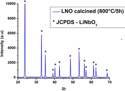
Figure 15 - SEM images of the LTO powders synthesized by a combined hydrothermal and wet-chemical technique at: (a) 570ºC, (b) 750ºC, and (c) 850ºC [102]. ... 37 Figure 16 - Glass-ceramic A-W in clinical use: intervertebral discs (A), artificial vertebrae (B), spinal spacer (C), iliac crests (D), porous spacer (E), and bone filler (F). [117] ... 40 Figure 17 - DTA and TG curves for Lithium niobate powder. DTA is denoting the exothermic and endothermic changes in the sample throughout the elevation of the temperature and TG is denoting the changes in weight as temperature increases from room temperature to 1200°C. ... 53 Figure 18 - DTA and TG curves for Lithium tantalate powder. DTA is expressing the exothermic and endothermic changes in the sample throughout the elevation of the temperature and TG is expressing the changes in weight as temperature increases from room temperature to 1500°C ... 54 Figure 19 - XRD pattern of lithium niobate powders calcined at 800ºC. The pattern reveals a monophasic material at this temperature. ... 55 Figure 20 - XRD patern of lithium tantalate powders calcined at 800ºC. The pattern reveals a monophasic material at this temperature. ... 56 Figure 21 - Particle size distribution for lithium niobate powders with a clear bimodal distribution. ... 57 Figure 22 - Particle size distribution for lithium tantalate powders with a clear bimodal distribution. ... 58 Figure 23 - SEM micropgraphs of lithium niobate powders after calcination and milling .A) 10 K magnification and B) 20 K magnification. ... 59 Figure 24 - SEM micropgraphs of lithium tantalate powders after calcination and milling .A) 10 K magnification and B) 20 K magnification. ... 60 Figure 25 - XRD patterns of lithium niobate powders on top after immersion in SBF for 0, 1, 3, 7, 15 and 21 days. In the bottom there is a representation of the JCPDS patterns for lithium niobate and hydroxyapatite for comparison with the peaks from XRD patterns of the synthesized powders. ... 62 Figure 26 - XRD patterns of lithium tantalate powders on top after immersion in SBF for 0, 1, 3, 7, 15 and 21 days. In the bottom there is a representation of the JCPDS cards for lithium tantalate and hydroxyapatite for comparison with the peaks from the XRD patterns of the fabricated powders. ... 63 Figure 27 - XRD patterns of PLLA/bioactive glass before and after soaking in SBF [134] ... 64
Assessment of bioactivity of selected ferroelectric ceramics
Pedro Tiago A. Félix
11
Figure 28 - EDS graph showing the elemental peaks present in the LNO powder sample that was immersed in SBF for 7 days. ... 66 Figure 29 – SEM micrographs of apatite-like structures in lithium niobate powders after soaking in SBF for 15 days with A) 10 K magnification and B) 20 K magnification ... 67 Figure 30 - EDS graph showing the elemental peaks present in the LNO powder sample that was immersed in SBF for 15 days. ... 68 Figure 31 - Representation of SEM images of apatite-like structures in lithium niobate powders after soaking in SBF for 21 days with A) 10 K magnification and B) 20 K magnification. ... 69 Figure 32 - EDS graph showing the elemental peaks present in the LNO powder sample that was immersed in SBF for 21 days. ... 70 Figure 33 - Representation of SEM images of apatite-like structures in lithium tantalate powders after soaking in SBF for 7 days with A) 10 K magnification and B) 20 K magnification ... 72 Figure 34 - EDS graph showing the elemental peaks present in the LTO powder sample that was immersed in SBF for 7 days. ... 73 Figure 35 - Representation of SEM images of apatite-like structures in lithium tantalate powders after soaking in SBF for 15 days with A) 10 K magnification and B) 20 K magnification ... 74 Figure 36 - EDS graph showing the elemental peaks present in the LTO powder sample that was immersed in SBF for 15 days. ... 75 Figure 37 -Representation of SEM images of apatite-like structures in lithium tantalate powders after soaking in SBF for 21 days with A) 10 K magnification and B) 20 K magnification ... 76 Figure 38 - EDS graph showing the elemental peaks present in the LTO powder sample that was immersed in SBF for 21 days. ... 77 Figure 39 - SEM micrographs of fluorapatite seeds; bottom micrograph is related to a medium-later stage of development of the fluoroapatite seeds [135]... 78 Figure 40 - FTIR-ATR spectra of LNO powders in 0 days immersion and after immersion in SBF for 1, 3, 7, 15 and 21 days. ... 80 Figure 41 - FTIR spectra of LTO powders before and after immersion in SBF for 1, 3, 7, 15 and 21 days. ... 81 Figure 42 - ICP curve for Ca, P and Li concentration in the SBF that was in contact with the lithium niobate powders from 0 days to 21 days. ... 82
University of Aveiro – Masters in Materials and Biomedical Devices 2012
12
Figure 43 - Variation of Ca, P, and Si ionic concentration on SBF after
PLLA/bioactive glass immersion [134]. ... 83
Figure 44 - ICP curve for Li concentration in the SBF that was in contact with the lithium tantalate powders from 0 days to 21 days. ... 84
Table Index
Table 1 - Important properties of Lithium niobate, lithium tantalate and barium titanates [40,56-61,63,66,139]. ... 28Table 2 - Ionic concentration of human blood plasma and SBF [117] ... 41
Table 3 - Chosen precursors for lithium niobate powder synthesis ... 45
Table 4 - Chosen precursors for lithium tantalate powder synthesis ... 45
Table 5 - Display of the order, quantity, supplier and purity of the reagents used for the preparation of 1L SBF [121]. ... 48
Table 6 - Ca/P ratio calculated for LNO powders after immersion in SBF for 7, 15 and 21 days. ... 70
Table 7 - Ca/P ratio calculated for Lithium Tantalate powders after immersion in SBF for 7, 15 and 21 days. ... 77
Table 8 - Bonds present in the LNO and LTO: vibration frequency and mode of vibration associated [67, 71, 75, 92, 102, 138 ] ... 79
Assessment of bioactivity of selected ferroelectric ceramics
Pedro Tiago A. Félix
13
ABBREVIATIONS
DTA – Differential thermal analysis
EDS – Energy-dispersive X-ray spectroscopy
FTIR-ATR - Fourier transform infrared spectroscopy - Attenuated total reflectance
HAp – Hydroxyapatite
ICP – Inductively coupled plasma
JCPDS – Joint Committee on Powder Diffraction Standards
LNO – Lithium Niobate
LTO – Lithium Tantalate
PLZT – lead lanthanum zirconate titanate
PZT – Lead Zirconate Titanate
SBF – Similated Body Fluid
SEM – Scanning electron microscope
Tc – Curie temperature
TGA – Thermogravimetric Analysis
University of Aveiro – Masters in Materials and Biomedical Devices 2012
Assessment of bioactivity of selected ferroelectric ceramics
Pedro Tiago A. Félix
13
1.
INTRODUCTION
1.1. Endogenous electrical currents in living organisms
The ability for humans and animals to generate endogenous electric signals, termed “animal electricity”, was documented in 1792 by Luigi Galvani when he noticed that an accidental sparked discharge caused frog muscle fibers to contract [1].
Figure 1 – Luigi Galvani (1792) [2]
Since this initial observation, it has been generally accepted that all organisms are electrodynamic systems, with large but stable gradients [3].
It has been reported that organisms from bacteria to mammals are sensitive to electromagnetic fields, [4] and these has been known to affect cell division rates, [5] tissue growth and wound repair [3]. So, through this knowledge it can be said that, tissues which generate endogenous electrical signals have a higher capacity to regenerate.
When a tissue has been damaged, injury potential creates steady electric fields, which exist locally for days after the insults. These potential differences result largely from ion flux through leaky cell membranes (Figure 2) and have been described as direct current-like, decay with time and have been estimated to be between 1 and 2 V/cm at the surface of wounds [6]. Wound healing is a dynamic response which occurrs together with cells, citokines, and enzymes, but research
University of Aveiro – Masters in Materials and Biomedical Devices 2012
14
has indicated that electrical gradients generated by injured tissue may be an integral part in the regeneration process [7].
Figure 2 – Potential differences in a cell membrane; the ion exchanges are regulated by particular structures located within the membrane known as transport proteins. [8]
Measurements recorded during embryonic growth demonstrate that substantial endogenous current exist as early as fetal development [7]. These electrical signals function as a natural control system, ensuring proper cellular expression, [9] and facilitating cell migration and orientation, known as galvanotropism [6.10-12]. This ability cells are provided with also enable different immune responses, embryo development and the spread of cancer. All these governing electrical responses are present in all animals, but have been known to be uniquely dependent on species type. In the case of newts, who have the ability to fully regenerate injured extremities, large electrical currents have been recorded during the limb regeneration process (Figure 3) [8].
Assessment of bioactivity of selected ferroelectric ceramics
Pedro Tiago A. Félix
15
Figure 3 – Photograph of newt limb regeneration. Within 30 to 40 days, newts had regenerated their lost limbs and digits [13].
Observations that endogenous electrical currents affect tissue growth and repair has spurred interest in exogenous electrical stimulation from accelerating bone healing and remodeling in the field of orthopedics. However, exogenous electrical stimulation has been clouded with uncontrolled variations in experimental design [14] and the utility of these devices is still a controversial topic in the peer-reviewed literature [7,14]. Therefore, it is of scientific purpose to investigate the use of exogenous electrical stimulation for bone healing, to identify classical problems in order to improve the current understanding of this topic, and [5] to present evidence of future applications of electrical stimulation through the use of piezoelectric and ferroelectric materials.
1.2. Bone – from a transducer point of view
Bone is a highly organized, anisotropic tissue, [15] which serves as a reservoir for calcium and phosphate, a site for hematopoiesis and provides the structural support required for movement [16]. Bone remodeling is a dynamic system. [17] It is coordinated by cells, [18] hormones, [19] and enzymes, [17] and is strongly influenced by age, [20] activity level, [21] and mechanical loading. [22,23]
Physical forces exerted on bone alter bone architecture and is a well-established principle known as Wolff’s Law [24].
University of Aveiro – Masters in Materials and Biomedical Devices 2012
16
It has been hypothesized by Frost [22] that a minimal effective strain is required to maintain bone architecture and physiology, and that bone strains rarely exceed 3% in vivo [26].
The principle that mechanical deformations of bone alter endogenous electrical signaling, and subsequent control of bone cell activity has been well regarded in the peer-reviewed literature [25,27]. However, it was not until the 1980’s that the electromechanical properties of bone were postulated as a biophysical basis for Wolff’s Law [27,28].
While it has been noted that mechanically deformed or actively remodeling bone always produces electrical current in vivo, [29] and is electronegative with respect to the resting environment, [30-33] bone formation and electrical stimulation were not initially considered to be an integrated system.
Successful bone growth results from a combination of both competent mechanical strain stimuli and endogenous electrical currents. [34] Correlations between bone formation rates and bioelectric potentials have been demonstrated by the ability of rabbit tibias to spontaneously generate potential differences up to mV in vivo [35].
The reformation that electrical signaling affected bone growth did not occur until stress generated potentials, known as piezoelectricity, emerged in the peer-reviewed literature.
1.3. The piezoelectric effect
Piezoelectricity was first reported by Jacques and Pierre Curie in 1880 when investigating the effect of charge generation through applied force in crystals of Rochelle salt (sodium potassium tartrate), quartz, and tourmaline. Piezoelectricity is characterized by a generation of electricity through applied pressure. This is known as the “direct piezoelectric effect”, where a compressive or tensile force produces a potential difference across the opposite faces of the crystal. The “converse effect” is also observed such that a crystal will become strained in response to the applied electric field [36].
Assessment of bioactivity of selected ferroelectric ceramics
Pedro Tiago A. Félix
17
Figure 4 - Illustration of piezoelectric behavior. The direct effect: application of (a) compressive or (b) tensile force generates charge on the opposing faces and a potential difference. The converse effect: an applied electric field either (c) equal or (d) opposite of the material’s polarity, causes the material to strain [37].
1.3.1. The piezoelectric effect – from an ionic flux point of view
Piezoelectricity can also be described by considering an ionically bonded crystalline solid and the distribution of ions within an individual unit cell. If this distribution of ions is asymmetric, an electrical dipole is generated [37].
When the dipole is mechanically strained, the movement of the positive and negative ions produce a net polarization – direct effect. On the other hand, the application of an electric field causes ionic movement, since alignment of the dipole with the field direction is preferable, producing a change in dimension of the dipole and a consequent mechanical change in the material at the macroscopic level – converse effect [36,37].
University of Aveiro – Masters in Materials and Biomedical Devices 2012
18
1.4. Piezoelectricity in the bone
The realization that biological tissue had the ability to generate electrical signals first was reported by Eiichi Fukada and Iwao Yasuda’s work on piezoelectricity with mature rabbit’s femurs in the 1950’s [29,31,36-38].
Figure 5 - Eiichi Fukada - 1995 Recipient of the Jean-Leonard-Marie Poiseuille Award Outstanding and Creative Work in Electro-Biorheology and Hemorheology [39].
Bone specimens, harvested from human and ox femurs, demonstrated that stress-generated potentials were created by the shear forces of collagen fibers [38] and the deformation of fluid-filled channels, named Haversian and Volkman channels (Figure 6) [40,41].
Assessment of bioactivity of selected ferroelectric ceramics
Pedro Tiago A. Félix
19
Figure 6 - Schematic of bone structure, demonstrating the position of the collagen fibers inside the Haversian canals [42].
Fukada and Yasuda noted that when a bone was submerged in acid for 3 weeks to remove the apatite crystals between the collagen fibers, electrical gradients were still produced [38].
Generation of electric potentials as described by Bassett and Becker [41] reaffirmed that mechanical deformation caused electrical stimuli and subsequently controlled osteogenic growth. Thus, the amplitude of electrical potentials was dependent on the rate and magnitude of bone loading, while polarity was determined by the direction of the deformed bone [44].
In vivo experimental recordings from the human tibia while walking has indicated a piezoelectric response as high as 300 mV [29].
The piezoelectric behavior of bone has been known to be strongly influenced by the state of the biological tissue. Because 10-15% of bone may be remodeling at any given moment, [18,45] there has been evidence to support natural variations in piezoelectricity over time [46].
Hydration of the host bone has been known to play an unique role in piezoelectricity, given that water distribution through the pores in bone and extracellular space naturally decrease over time and with progressive mineralization. [47] The piezoelectric coefficients decrease with increasing water content due to absorption of free water [47].
University of Aveiro – Masters in Materials and Biomedical Devices 2012
20
The clear coupling between mechanical forces and endogenous currents required for maintaining skeletal architecture has been clearly demonstrated since the 1950’s. However, the use of exogenous electrical stimulation for expediting osseous growth dates back to the early 1840’s [37,49].
In 1910 the Carnegie Foundation condemned the use of electrical stimulation and relegated electrotherapy to a scientifically unsupportable position causing it to fade almost completely from medical practice. [50]
Piezoelectric materials generally have some form of asymmetry, leading to the generation of an electrical dipole that reacts to an applied mechanical stress or an electric field. For the bone the electrical dipole seems to form as a result of asymmetric collagen molecules. Collagen fibers oriented parallel to the long axis of the bone which forms helices within the lamellae forming the Haversian systems, oriented at various angles [38,50,51].
The overall orientation of the collagen is generated in the direction of the bone axis and results in piezoelectric properties and the development of charge in response to the application of a mechanical load [36, 41-45, 51].
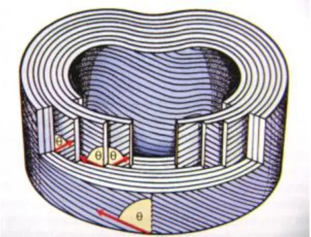
Figure 7 - The annulus fibrosus in human vertebrae with the nucleus pulposus removed. The collagen fibers are arranged in multiple concentric layers with consecutive rings running in alternating directions, left and then right, but always with an orientation of 65 degrees [52].
Assessment of bioactivity of selected ferroelectric ceramics
Pedro Tiago A. Félix
21
In addition to the piezoelectric effect, streaming potentials can also result in electrical activity in bone. The electromechanical properties of wet and dry bone are different and cannot be explained by a single mechanism: both streaming potentials and piezoelectricity are thought to occur in live bone [50]. The Extracellular Matrix (ECM) is negatively charged due to the presence of proteins. It is deformed in mechanical loading, inducing a flow of positively charged fluid and therefore developing streaming potentials [51,54].
The interstitial fluids (water solvent containing sugars, salts, fatty acids, amino acids, coenzymes, hormones, neurotransmitters, as well as waste products from the cells) are thought to move within bone canaliculi [54] which have a very small diameter in the order of 0.2 µm. Streaming potentials are thought to be part of the mechanosensory mechanisms in bone by which mechanical forces influence bone remodeling [50,53-55].
Within this context new generations of biomaterials are of interest in the current modern days; these materials seek to influence healing by mimicking the electrical effects in bone, namely the creation of a negative or positive charge on the surface of the biomaterial.
Two possible ways employed to create a surface charge are: [56]
To polarize an ionic biomaterial by application of an electric field at elevated temperature to displace cations and anions in opposite directions.
To develop a piezoelectric biomaterial so that a charge is generated under the application of a mechanical stress.
1.5. Ferroelectricity
Most of the investigations on piezoelectric materials have been carried out mainly on materials containing barium titanate or PZT [40,56].
Ferroelectrics represent a valuable subgroup of piezoelectric materials, characterized by the presence of a spontaneous polarization in the unstrained state and the capability to re-orientate in the orientation of polarization.
University of Aveiro – Masters in Materials and Biomedical Devices 2012
22
Ferroelectricity corresponds to certain crystal structures, of which the perovskite configuration is the most significant one, although it’s not the only one existing for ferroelectric materials [56].
A better understanding of the ferroelectric phenomenon can be described by taking a look at small molecules. A molecule that is symmetric, such as methane (CH4) has no dipole, but many simple molecules are not symmetric (e.g. H2O) and have a dipole moment. It can be postulated that a structure that has a centre of symmetry cannot be ferroelectric. In other words, a ferroelectric material has a permanent electric dipole, and is named after and in analogy to a ferromagnetic material (e.g. Fe) that has a permanent magnetic dipole. Those that have a unique polar axis are ferroelectric and have a spontaneous electrical polarization. The others show the piezoelectric effect, wherein an electrical polarization is induced by application of an elastic stress; extension or compression will induce electrical polarization of opposite signs [57].
In terms of applied fields and polarization of the materials, when an electric field E is applied to an ideal insulator a short-range dislocation of the positive and negative charge centre causes the appearance of electric dipole moments in the material. The material is called a dielectric and is said to be polarized. If there is a linear relationship between the applied field E and the induced polarization P and P disappears when E is removed the material is called a linear dielectric [58]. This linear relation in the dielectric material is described in Figure 8.
Assessment of bioactivity of selected ferroelectric ceramics
Pedro Tiago A. Félix
23
Figure 8 – Dielectric linear polarization [59].
If at zero field a mechanical stress provokes the development of electric charges (polarization) these materials are called piezoelectrics. Piezoelectricity is the ability of certain crystalline materials to develop an electrical charge proportional to a mechanical stress or vice versa [56].
In a piezoelectric the relationship between the applied deformation and the induced polarization is linear and reversible. In a piezoelectric the magnitude of P depends on the magnitude of the stress and the sign of the produced charge depends on the type of applied stress (tensile or compressive). If, in zero field conditions, there are dipolar moments due to a non-symmetric structure, the materials will have spontaneous polarization and they are called pyroelectrics. Some pyroelectric materials have an additional property; the direction of spontaneous polarization can be switched by an applied electric field. These materials are called ferroelectrics. All ferroelectrics are piezoelectric and pyroelectric [58].
In ferroelectrics the relationship between the applied field and the polarization is described by a hysteresis loop, which means that ferroelectric materials demonstrate spontaneous polarization at zero field and, as a distinguishing feature of ferroelectrics, the direction of the spontaneous polarization can be reversed by an applied electric field, yielding an hysteresis curve [56-58]. The electrical field at
University of Aveiro – Masters in Materials and Biomedical Devices 2012
24
which the polarization is reversed is called the coercive field (Ec) [58]. Figure 9 discribes a typical hysteresis loop of a ferroelectric.
Figure 9 – Typical hysteresis loop of a ferroelectric, notice that the spontaneous polarization is present even at zero field after pooling [59].
Ferroelectricity is a phenomenon which was discovered in 1921 [56-61]. Ferroelectricity has also been called Seignette electricity, as Seignette or Rochelle Salt (RS) was the first material found to show ferroelectric properties such as a spontaneous polarization on cooling below the Curie point, ferroelectric domains and a ferroelectric hysteresis loop [60, 61].
A huge leap in the research on ferroelectric materials came in the 1950's, leading to the widespread use of barium titanate (BaTiO3) based ceramics in capacitor applications and piezoelectric transducer devices. Since then, many other ferroelectric ceramics including lead titanate (PbTiO3), lead zirconate titanate ((Pb[ZrxTi1-x]O3 0≤x≤1); PZT), lead lanthanum zirconate titanate
((Pb0.83La0.17(Zr0.3Ti0.7)0.9575O3); PLZT), and relaxor ferroelectrics like lead
magnesium niobate ((PbO)3(MgO)(Nb2O5); PMN) have been developed and utilized for a variety of applications. Indeed, among inorganic crystalline ferroelectric materials, the perovksite group is particularly important, from the point of view of applications. These compounds have the general formula ABX3, where
Assessment of bioactivity of selected ferroelectric ceramics
Pedro Tiago A. Félix
25
A is a large cation, B is a much smaller cation and X is an anion, usually oxygen (Figure 10). The B cation tends to be displaced away from the center and that is essential for the ferroelectric effect to exist [61].
Figure 10 - Crystallographic structure of ABO3 perovskite [62].
The materials with the highest piezoelectric coefficients belong to the lead based perovskite family. Besides the ability to design the physical properties required for certain applications, by formation of solid solutions, the possibility of fabrication as single crystals, ceramics, textured ceramics and thin and thick films adds value to this family of materials [58].
The biggest use of ferroelectric materials has been in the areas of dielectric ceramics for capacitor applications, ferroelectric thin films for non-volatile memories, piezoelectric materials for medical ultrasound imaging and actuators, and electro-optic materials for data storage and displays [60, 61].
As with the bone, the origin of piezoelectric behavior in ferroelectric materials comes from the formation of an electrical dipole due to an asymmetric distribution of ions [47, 58].
University of Aveiro – Masters in Materials and Biomedical Devices 2012
26
1.5.1. Ferroelectric ceramics as implant materials
If we take for example, BaTiO3 as a ferroelectric ceramic, it is verified that at high temperatures, its structure has a simple cubic unit cell with large cations (Ba) at the corner sites, a smaller cation (Ti) in the body center and face centered oxygen ions (O) [60]. This symmetrical unit cell has no electric dipole and is neither ferroelectric nor piezoelectric.
Below a critical temperature known as the Curie point, Tc, the symmetrical cubic structure transforms to an asymmetrical structure, typically tetragonal or rhombohedral. Associated with this transformation is a spontaneous polarization, which results from the relative shift of ions with respect to the unit cell [36,56,57].
The displacement of the ions is restricted to specific crystal directions, allowing polarization toward one of the six faces in the tetragonal cell, or toward one of the eight corners for the rhombohedral phase [60].
Regions in a ferroelectric material such as BaTiO3 where the unit cells have equal polarization directions are known as domains. After sintering a ferroelectric ceramic and cooling below the Curie temperature (Tc), domains will form in a random arrangement, such that there is no net polarization in the bulk material.
To align the domains in a single direction and make the material piezoelectric, it is necessary to “pole” the material [37,56].
1.5.2. Polling processes
The initial material consists of randomly orientated domains.
The material is heated to an elevated temperature below the Tc to facilitate domain motion, and a high electric field applied to orientate domains in a single direction [37, 61].
The domains move smoothly in response to the applied electric field [61]. The material is then cooled to room temperature while the electric field is still applied.
Assessment of bioactivity of selected ferroelectric ceramics
Pedro Tiago A. Félix
27
On removal of the electric field at ambient temperatures, the material retains a net polarization producing a poled ferroelectric ceramic with piezoelectric behavior, despite some domains may change direction [37].
1.6. Lithium Niobate and Lithium Tantalate as ferroelectric
ceramics
Lithium niobate and lithium tantalate are two ferroelectric ceramics, which are important for applications in many technological fields [63, 64, 66].
They present ferroelectric properties at room temperature and may be grown in the form or large optical-quality single crystals [63,66].
In terms of crystallography, lithium tantalate and lithium niobate have similar crystallographic structures and consequently, same space group – R3c, with only slight differences in the lattice and positional parameters [64, 67-70].
Thus, the piezoelectric properties of LNO and LTO single crystals are highly dependent on the crystal orientation, which is related to the symmetry and the structure of these compounds. So it can be said, that in order to enhance the piezoelectric properties, the optimal directions of LNO and LTO should be considered [71].
In Table 1 there’s a list of important properties and data relative to single crystals of lithium niobate, lithium tantalate and barium titanate.
University of Aveiro – Masters in Materials and Biomedical Devices 2012
28
Table 1 - Important properties of Lithium niobate, lithium tantalate and barium titanates [40,56-61,63,66,139].
LiNbO
3LiTaO
3BaTiO
3Stable Phase Tetragonal Tetragonal Tetragonal Molar Mass (g/mol) 233.192 147.846 235.887 Melting Temperature (°C) 1260 1650 1625 Density (g/cm3) 4.65 7.45 6.02 Electrical Properties Curie Point (°C) 1210 610 135 Relative dielectric constant at 1 kHz (ε33) 27.9 42.8 109 Electromechanical Properties Electromechanical coupling factor (k33) (%) 47 18 56 Piezoelectric charge coeficient (d33) (10-12C/N) 6 5.7/8 85.7 Piezoelectric strain coeficient (e33) (C/m²) 1.33 1.93 6.71
1.6.1. Lithium niobates main properties and applications
Ferroelectric properties in lithium niobate (M = 147.846) were first discovered by Matthias and Remeika in 1949. Lithium niobate is characterized by a trigonal crystal system and the respective space group is R3c. This material has a melting temperature of 1253ºC, which opened a wide window of applications as a ferroelectric and piezoelectric and may be utilized even more if proven bioactive and biocompatible [66].
Assessment of bioactivity of selected ferroelectric ceramics
Pedro Tiago A. Félix
29
Lithium niobate is an important functional material that has been widely used in the modern science and technology due to its large pyroelectric, piezoelectric, electro-optical, photo-elastic, ferroelectric coefficients and good optical, electric and electro-mechanical properties. With the development and application of functional devices, the synthesis of LNO powders attracts much attention and becomes an interesting topic in the field of LNO crystals, for instance, it can be utilized to create efficient holographic memory devices, second harmonic generation and optical parametric oscillation devices [72].
Figure 11 - LiNbO3. Phase diagram of system x Li2O·(1-x) Nb2O5 [73].
LNO powders were traditionally synthesized by the conventional high temperature solid-state method at 1200°C from the raw powders of Li2CO3 and Nb2O5, which often results in the growth of inhomogeneous large grains, the formation of additional phases (Nb2O5 and LiNb3O8) and possible loss of the crystal stoichiometry due to the easy volatilization of lithium at high temperature.
University of Aveiro – Masters in Materials and Biomedical Devices 2012
30
During the recent years, a number of wet chemical synthesis have been reported for the synthesis of LNO powders, such as the hydrothermal route [69], water-soluble complex method [72], solvothermal route [74] and metal alkoxides method [75].
Figure 12 - Crystallographic structure of lithium niobate: view along the c-axis in one unit cell [76].
The crystallographic structure of LNO crystals consists of distorted oxygen octahedral by sharing their common faces along the c-axis lattice or edges at the ab plane, which forms a trigonal (c-axial) lattice. In the ferroelectric phase, both Nb5+ and Li+ cations are displaced from the centers of their respective octahedral [74, 75]. Additionally, in the three dimensional frame, NbO6 octahedra link each other by sharing their common corners and the same happens for the LiO6 octahedra [74-76].
Assessment of bioactivity of selected ferroelectric ceramics
Pedro Tiago A. Félix
31
1.6.2. Lithium niobate synthesis processes
The properties of ceramics are affected by the characteristics of the powder, such as particle size, morphology, purity, particle size, size distribution and chemical composition [63, 64].
The nature and quality of ceramic powders used in fabricating a final ceramic device or piece are key for determining the quality, yield and performance of that ceramic. This is especially true for the powders used in electronic ceramics [65].
1.6.2.1. Solid-state reaction
Solid-state reaction of lithium niobate is the traditional method for synthesizing powders, it is based on the simple mixing of the treated powder precursors through a mixing milling process, followed by calcination. The mixture is then re-milled if necessary (in order to remove agglomerates) and after shaping the green body is sintered at high temperatures [70-76].
Single-phase stoichiometric materials with a reproducible Li/Nb ratio are however difficult to obtain by solid-state reaction, due to the evaporation of Li2O component at high temperatures. A reaction in the 1:1 mixture of Li2CO3 and Nb2O5 powders may yield Li3NbO4 and LiNb3O8 in the whole system, besides LiNbO3 [71,73,74].
1.6.2.2. Chemical synthesis of stoichiometric lithium niobate powders
LNO powders may be chemically prepared by water-soluble complexes, this method is one of the reasonable ways to obtain stoichiometric lithium niobate powder [75].
The method involves milling Li2CO3 and Nb2O5 powders, followed by the addition of some urea powders. The misture is then put into a heater, the temperature of the heater is continuously increased and kept at 600ºC for 5h.
University of Aveiro – Masters in Materials and Biomedical Devices 2012
32
Despite the potential of such a water-soluble complex idea, there are still some problems existing in the wet chemical synthesis, such as the difficulty of solving niobium oxide and uneasy control of reaction conditions [77].
1.6.2.3. Combustion synthesis of Lithium niobate powders
The combustion synthesis is an attractive technique for producing LNO powders [75,77], whose advantages are that an organic compound like urea gives out heat that can be supplied to the precursors (Li2CO3 and Nb2O5 powders) in order to decrease the reaction time, and reduce the reaction temperature (600ºC). This method doesn’t need any solvent involved in the reaction process (neither organic nor inorganic), thus the generation of impurities can be decreased [77].
The SEM micrographs in Figure 13 are here presented in order to further compare with the SEM results from the experiment presented in our own work.
Assessment of bioactivity of selected ferroelectric ceramics
Pedro Tiago A. Félix
33
Figure 13 - SEM images of LNO powders produced by combustion method and calcined at various temperatures for 1 h. (a) 900°C, (b) 950°C, (c) 1000°C, (d) 1050°C, and (e) 1100°C [77].
University of Aveiro – Masters in Materials and Biomedical Devices 2012
34
1.6.3. Lithium Tantalate main properties and applications
Like with lithium niobate, ferroelectricity in lithium tantalate (M = 235.887) was first discovered by Matthias and Remeika in 1949, and this ferroelectric also has a stable trigonal crystal system and its space group is also R3c. Its melting temperature goes even further than that of lithium niobate which means its range of applications can be even greater (Tmelt = 1650°C). The crystallographic structure of lithium tantalate is very similar to lithium niobates [63-65,78,82,93-98].
Lithium tantalate is one of the most widely used electro-optic materials because of its excellent ferroelectric, piezoelectric, pyroelectric and photo-refractive properties [79-85]. It is also utilized in mobile telephones for intermodulation of saw filters, in infra-red image detectors, waveguide lasers and as acoustic wave devices to monitor enzyme concentrations [78-81,86-88]. It was also investigated as a photocatalyst for the reaction of photocatalytic hydrogen generation [88]. Although single crystals of LiTaO3 have many applications, there are still some restrictions to its acquisition due to its high cost and difficult fabrication. On the other hand, polycrystalline LTO ceramics can be made with a larger size and more complex shapes [80]. Still, most studies were concentrated on the growth and properties of LiTaO3 single crystal [79,83].
LiTaO3 traditional powder preparation is based on the solid-state reaction, but this method requires heat treatment at relatively high temperatures (>1000 ⁰C) and volatilization of Li2O may occur [63-66,78-83,88-99]. This volatilization of Li2O may happen due to its significant low vapor pressure at the processing conditions, which makes it difficult to control the stoichiometry [82-86]. Therefore, inhomogeneity in composition and coarse particles may be encountered. [78,84]
Various methods are reported in the peer-review for LiTaO3 powder synthesis including sol-gel process, solid solution systems [79,85-88,92] and combustion, co-precipitation, hydrothermal, alkoxide and citrate gel methods. [57,63,65,78,80] Among these methods, alkoxides, hydrothermal and colloid emulsions are time consuming and involve highly unstable alkoxides, this causes difficulty in controlling and maintaining the reaction conditions [84].
Assessment of bioactivity of selected ferroelectric ceramics
Pedro Tiago A. Félix
35
1.6.4. Lithium tantalate synthesis processes
1.6.4.1. Solid-state reaction
Alike solid-state reaction of LNO powders, this solid-state reaction is the traditional method for sintering LTO powders. Solid state reaction although easy, may lead to composition inhomogeneity and coarse particles [100].
Thus, LTO is difficult to be sintered because of volatilization of Li2O at high temperature (>1300 ºC) [65].
1.6.4.2. Chemical preparation of lithium tantalate powder
Chemical routes, such as precipitation from solution, or sol-gel processes, have received considerable attention [100]. These chemical routes can offer many advantages over conventional processes, such as high purity, and molecular homogeneity. These methods have been widely used for the synthesis of powders for electronic ceramics applications, such BaTiO3 [102] and PLZT [104].
Jean et. al. [65], came up with a chemical preparation of spherical lithium tantalate powder method, by spray drying lithium tantalate percursors – lithium acetate and tantalum ethoxide. Hydrous lithium acetate was first dissolved into methoxyethanol and dehydrated at 125 ⁰C for 30 min and precipitated anhydrous lithium acetate.
After cooling the acetate precipitate was redissolved at 125 ⁰C and this cycling process continued for 2h to complete the chemical reaction between lithium acetate and tantalum ethoxide. The solution was cooled at room temperature and then spray dried [65].
Figure 14 will be useful for comparing this experiment with lithium tantalate in the results chapter.
University of Aveiro – Masters in Materials and Biomedical Devices 2012
36
Figure 14 - SEM micrograph of lithium tantalate powder calcined at 800~ in air for 2 h prepared by jean et al. with a chemical route [65]
1.6.4.3. Combined hydrothermal and wet-chemical technique for LTO powder synthesis
Ta2O5 is very stable and can hardly be dissolved by regular wet-chemical routes. A successful attempt on dissolving tantalum (V) oxide was done by Muthurajan et. al, using hydrofluoric (HF) acid (40%) in a hot water bath for 10h. However, HF acid is strongly corrosive and toxic. It still remains a relatively difficult task to synthesize high quality LTO powders from nontoxic starting materials [101]. Zheng F. et al. [102], utilized a combined hydrothermal and wet-chemical technique to produce LTO powders, this synthesis method involves nontoxic raw materials, mainly tantalum hydroxide (Ta(OH)5) and lithium carbonate (LiCO3). Ta(OH)5 was first dissolved in hydrochloric acid through a hydrothermal process, followed by addition of citric acid (CA) to form stable Ta-CA complex. After pH adjustment with ammonia and addition of Li2CO3, pure LT powders were obtained by calcination at 720 ⁰C for 2h.
Assessment of bioactivity of selected ferroelectric ceramics
Pedro Tiago A. Félix
37
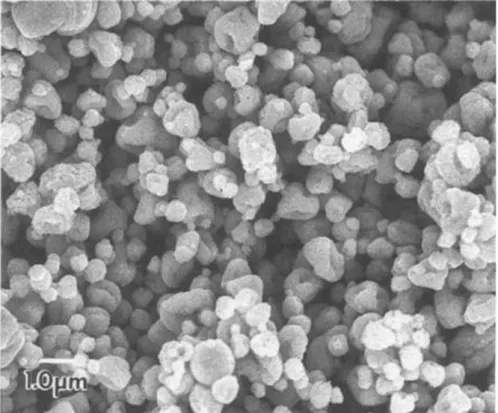
Compositional, microstructural, and morphological aspects of the final product were evaluated with XRD and SEM. Thermal behavior and calcination temperature were determined by thermal analysis [102]. In figure 15, there’s a micrograph of LTO powders resulted from this experiment, the morphology of these powders is useful for future comparison.
Figure 15 - SEM images of the LTO powders synthesized by a combined hydrothermal and wet-chemical technique at: (a) 570ºC, (b) 750ºC, and (c) 850ºC [102].
1.7. Bioceramics
Ceramic materials used to regenerate and replace damaged parts of the human body, are designated as bioceramics [103-112].
To be applied as biomaterials, these ceramics must satisfy certain biological conditions such as, non-toxicity, non-carcinogenic, not allergic, not inflammatory, biocompatible and biofunctional during the implantation period [108]. Bioceramics can be monocrystalline, polycrystalline, glass, glass-ceramic or composite.
The clinical success of a bioceramic depends, essentially, on the formation of a stable interface with the bone tissue and the combination of the mechanical properties of both implant and living tissue. The adhesion mechanism to the living tissue is directly related to the type of biological response induced by the bioceramic in the interface between the material and for example, the bone tissue [110-112].
There are four main kinds of biological response and adhesion processes that allow the distinguishing of bioceramics from one another, mainly, bioinert,
University of Aveiro – Masters in Materials and Biomedical Devices 2012
38
resorbable, porous and bioactive [112]. These four biological responses will be described in the topics below.
1.7.1. Bioinert ceramics
These bioceramics do not establish chemical or biological bonds with the living tissue, moving according to the tissue and inducing the formation of a fibrous capsule in the interface material-tissue [110-113]. This movement gradually decreases the functionality of the implant, leading to its replacement [110-112]. The thickness of the fibrous capsule depends on the material and relative movement. The development of implants with small protrusions on its surface allowed a better fixation and decrease of relative movement. This type of fixation is designated as morphological fixation [112].
Some of the most recognized bioinert materials are alumina and zirconia for example [111].
1.7.2. Resorbable ceramics
Resorbable ceramics are known to gradually degrade as time passes, being replaced by living tissue, such as the bone [108,112-115]. There are however, some issues that should be stressed out one of the most important is that this biomaterial should maintain its resistance and stability during the period in which degradation and replacement processes occur. In this line of thought, it is imperative that in order for these bioceramics to be successfully developed, the rate of the degradation should be similar to the rate of the tissue regeneration. [112-114].
Good examples of resorbable ceramics are the calcium-phosphate based ceramics. The chemical composition of these ceramics depends on the ratio Ca/P of the precursors and processing conditions [113].
Assessment of bioactivity of selected ferroelectric ceramics
Pedro Tiago A. Félix
39
1.7.3. Porous ceramics
Macroporous bioceramics establish biological bonds with the living tissue that grows in the insides of its pores [110]. This is designated as biological fixation, it’s more resistant than the morphological fixation and there’s a decrease in the possibility of implant motion [112-114]. These pores must have dimensions superior to 100-150 µm, otherwise vascular tissues essential to tissue growth will not develop. This type of interconnected pores allows blood supply and enables a more effective and healthy tissue growth. On the other hand, porosity diminishes the implant resistance [112-114]. Corals are a very good example of porous biomaterials [111-113].
1.7.4. Bioactive ceramics
A bioactive material is defined as a material with the capacity of developing a specific biological response in the interface material-tissue, resulting in the formation of physical and chemical bonds between the biomaterial and the adjacent tissues [109, 111-116]. The most recognized bioactive materials clinically used are, the bioglasses (Bioglass
®
), bioactive glass-ceramics (Cerabone A/W®
), densified Hydroxiapatite and bioactive composites (PE-HAp; Bioglass®
– stainless steel).The resistance and the mechanism for this bond are individual properties, meaning that these properties depend mainly on the implant material and type of tissue to which it is attached to [101-104], although orientation, age and trial conditions may also play an important role in these mechanisms [112].
Bioglass® and bioglass-type glasses in the form of particulates have gained a lot of successes in periodontal bone repair [117]. Glass-ceramic A-W, owing to its superior mechanical strength and bone-bonding ability, has been applied as artificial vertebrae, intervertebral discs and iliac crests in dense bulk form.
University of Aveiro – Masters in Materials and Biomedical Devices 2012
40
Figure 16 - Glass-ceramic A-W in clinical use: intervertebral discs (A), artificial vertebrae (B), spinal spacer (C), iliac crests (D), porous spacer (E), and bone filler (F). [117]
Also, hydroxiapatite (Ca10(PO4)6(OH)2) is one of the most well-known phosphates in the biologically active phosphate ceramic family by virtue of its similarity to natural bone mineral [117].
Synthetic and biological hydroxyapatite has a variety of bioapplications and elicits the formation of an apatite layer at the interface with bone tissue. More on the importance of this apatite will be clarified in the next topic [118-120].
1.8. Bioactivity of a ceramic material in the bone
Histological examinations of bone tissue show that when a bioactive ceramic is in contact with the bone tissue, an apatite layer is formed on the ceramic surface and thereafter, the bone matrix integrates into the apatite [121-124]. Detailed characterization indicates that this apatite layer consists of nano-crystals of carbonate-ion containing apatite rich in Ca and P ions [112,113,115]. These characteristics make in fact, this apatite similar to the mineral phase in bone and, hence, bone cells like osteoblasts, can adhere proliferate, and differentiate on the apatite to form an extracellular matrix composed of biological apatite and collagen [120,125,126].
When this attachment occurs, a chemical bond is formed between the bone mineral and the surface apatite to reduce the interfacial energy between them. In other words, it is suggested that the formation of a layer of biologically active
Assessment of bioactivity of selected ferroelectric ceramics
Pedro Tiago A. Félix
41
bone-like apatite in the surface of the ceramic is an essential requirement for an artificial material to bond to living bone.
The in vivo formation of an apatite layer on the surface of a bioactive ceramic can be reproduced in a protein-free and acellular simulated body fluid (SBF), which is prepared to have an ion concentration nearly equal to that of human blood plasma, as depicted in Table 2 [117-122].
Table 2 - Ionic concentration of human blood plasma and SBF [117]
Ionic Concentration (nM) Na+ K+ Mg2+ Ca2+ Cl- HCO3- HPO42- SO4 2-Human plasma 142,0 5,0 1,5 2,5 103,0 27,0 1,0 0,5 SBF 142,0 5,0 1,5 2,5 147,8 4,2 1,0 0,5
Therefore, the in vitro bioactivity of an artificial material can be evaluated by examining the formation of apatite on its surface in SBF.
The morphology and composition of the apatite surface layer can be assessed by SEM/EDS, from which it is also possible to estimate the Ca/P ratio in the apatite.
The Ca/P atomic ratio for stoichiometric hydroxyapatite in the bone tissue is 1.667. If this ratio is found in the surface of materials immersed in SBF, it is likely that an apatite formation may be occurring [127,128].
The validity of the immersion tests in SBF to predict the in vivo bioactivity of a material was analyzed by Kokubo et al. [121]. The authors compiled and compared several studies on bioactivity in vivo and formation of the apatite surface layer of materials immersed in SBF and found that. a large group of materials exhibiting the formation of an apatite layer on its surface in SBF also showed to bind chemically to bone in vivo. These materials are: Bioglass
®
45S5, glass systems Na2O-CaO-B2O3-Al2O3-SiO2-P2O5, CaO-SiO2 and Na2O-CaO-SiO2, AW glass ceramics type Ceravital®
, calcium sulfate, hydroxyapatite sinteredUniversity of Aveiro – Masters in Materials and Biomedical Devices 2012
42
composite apatite /-TCP and polyethylene / AW-glass ceramic and also metallic oxide gels prepared by sol-gel: SiO2, TiO2 and TaO2. Generally, materials that didn’t show in vitro formation of apatite in SBF, did not show bioactivity in vivo. The phenomenon correlation between in vivo and in vitro is also quantitative, i.e. the faster the apatite layer is formed in the material in vitro, the faster will it bind with the bone tissue in vivo. There is at present a consensus on the acceptance that the bioactivity of a material in vivo can be predicted from its capability of forming an apatite layer when immersed in a synthetic physiological medium like SBF, provided that the material does not cause major inflammatory reactions or allergies, toxicity or carcinogenesis [122].
![Figure 3 – Photograph of newt limb regeneration. Within 30 to 40 days, newts had regenerated their lost limbs and digits [13]](https://thumb-eu.123doks.com/thumbv2/123dok_br/15812222.1080626/23.892.205.737.126.422/figure-photograph-newt-regeneration-newts-regenerated-limbs-digits.webp)

![Figure 6 - Schematic of bone structure, demonstrating the position of the collagen fibers inside the Haversian canals [42]](https://thumb-eu.123doks.com/thumbv2/123dok_br/15812222.1080626/27.892.182.759.129.460/figure-schematic-structure-demonstrating-position-collagen-fibers-haversian.webp)
![Figure 9 – Typical hysteresis loop of a ferroelectric, notice that the spontaneous polarization is present even at zero field after pooling [59]](https://thumb-eu.123doks.com/thumbv2/123dok_br/15812222.1080626/32.892.248.649.219.554/figure-typical-hysteresis-ferroelectric-spontaneous-polarization-present-pooling.webp)
![Figure 12 - Crystallographic structure of lithium niobate: view along the c-axis in one unit cell [76]](https://thumb-eu.123doks.com/thumbv2/123dok_br/15812222.1080626/38.892.182.741.292.791/figure-crystallographic-structure-lithium-niobate-view-axis-unit.webp)
![Figure 15 - SEM images of the LTO powders synthesized by a combined hydrothermal and wet-chemical technique at: (a) 570ºC, (b) 750ºC, and (c) 850ºC [102]](https://thumb-eu.123doks.com/thumbv2/123dok_br/15812222.1080626/45.892.156.763.311.482/figure-images-powders-synthesized-combined-hydrothermal-chemical-technique.webp)
![Table 5 - Display of the order, quantity, supplier and purity of the reagents used for the preparation of 1L SBF [121].](https://thumb-eu.123doks.com/thumbv2/123dok_br/15812222.1080626/56.892.180.775.519.963/table-display-order-quantity-supplier-purity-reagents-preparation.webp)