SCIENCE AND ENGINEERING
FRICTION RIVETING OF ALUMINIUM ALLOY 6056-T6 WITH SHORT-GLASS-FIBER-REINFORCED POLYAMIDE 6 COMPOSITE
Bruno Cordeiro de Proença
SCIENCE AND ENGINEERING
FRICTION RIVETING OF ALUMINIUM ALLOY 6056-T6 WITH SHORT-GLASS-FIBER-REINFORCED POLYAMIDE 6 COMPOSITE
Bruno Cordeiro de Proença
Thesis presented to Postgraduate Program in Materials Science and Engineering to achieve the MASTER DEGREE IN MATERIALS SCIENCE AND ENGINEERING.
Advisor: Dr. Leonardo Bresciani Canto (UFSCar/DEMa) Co-Advisor: Dr.-Ing. Sergio T. Amancio Filho (HZG/Germany) Financial Support: CNPq
ACKNOWLEDGEMENTS
The development of this MSc thesis counted with valuable contributions of many people whom I would like to thank:
- Prof. Dr. Leonardo Bresciani Canto for the opportunities, guidance, critiques and trust by giving me autonomy in my researches since my scientific initiation.
- Prof. Dr. Sergio T. Amancio-Filho for the opportunity, guidance, constructive critiques, friendship and trust by giving me autonomy in my research at HZG. - Dr. Jorge F. dos Santos for the opportunity to perform my internship at
WMP-HZG.
- Dr. Lucian Blaga for the support, encouragement, healthy discussions, friendship and for sharing his expertise in life and FricRiveting with me. - Employees of the DEMa/UFSCar and PPG-CEM that are dedicating their
lives for the intellectual and personal development of the students.
- All people from WMP-HZG. Special thanks to Menno Peters for helping me to perform some of my experiments.
- The Young Investigator Group. Special thanks to my colleagues André, Natalia, Natascha, Eduardo and Seyed for the support and friendship
- My dear friends from São Carlos and life, Carlos, Afonso, Guilherme, Fernando, Gustavos, Rafael, Vinicius, Ligia, Caio, Wesla, Lys, Yumi, Andressa for the personal support and for sharing experiences.
- Movimento Mapa Educação for the opportunity to make Brazil a better place to live.
- My family for the inspiration and unconditional love. Specially my parents and sister for the support, advices, values and opportunities. All my love is yours. - Janaina, my best friend and love, for her support, love, comprehension and
friendship.
ABSTRACT
Friction Riveting (FricRiveting) is a relatively new joining technique for metal-polymer hybrid structures. This master thesis was carried out to investigate the FricRiveting process for polyamide 6 reinforced with 30 wt% short glass fiber (PA6-30GF) and aluminum alloy 6056-T6. These materials were selected because of their current joint use in automotive structures. AA6056-T6/PA6-30GF friction-riveted joints were successfully produced. Peak temperatures monitored for the process achieved between 323 °C and 399 °C leading the plastic deformation and thus anchoring of the rivet. The metallic rivet had its microstructure changed during the process, with dynamic recovery and recrystallization being observed in the anchoring zone. Microhardness in the metallic rivet decreased by 40 % of the base material hardness in the anchoring zone, due to a possible dissolution of the precipitates in the aluminum matrix and dynamic recovery and recrystallization. Polyamide 6 degradation was investigated by viscosity measurements and ATR/FT-IR, the joint with the highest level of degradation showed a reduction of 19 % on viscosity average molecular weight and an increase of 2.4 % of the carbonyl index in relation to the base material. Despite this reduction of properties, the friction-riveted joints had a good mechanical performance under tensile loading. Two joining conditions fractured through the metallic rivet outside the composite plate, achieving 92 % of the ultimate tensile strength of the metallic rivet. The influence of the process parameters on the process temperature, viscosity average molecular weight and ultimate tensile force were studied through Box-Behnken Design of experiment, response surface methodology and analysis of variance. Regression equations for these responses were estimated and validated, and an optimized condition was selected. Post joining heat treatment was performed on the optimized joining condition, resulting in an increase of the joint ultimate tensile force up to 99 % of the metallic rivet ultimate tensile force. The durability of the optimized joint was evaluated through natural weathering. An expected negative effect of weathering on the joint ultimate tensile force was observed, strength decrease of 8.4 % after 6 months and 15.5 % after 12 months of exposure.
REBITAGEM POR FRICÇÃO DE LIGA ALUMÍNIO 6056-T6 EM COMPÓSITO DE POLIAMIDA 6 REFORÇADA COM FIBRA DE VIDRO CURTA
RESUMO
PUBLICATIONS
PROENCA, B.C., BLAGA, L.A., DOS SANTOS, J.F., CANTO, L.B., AMACIO-FILHO, S.T. Influência da Topografia da Superfície de Atrito do Rebite na Formação de Juntas de Alumínio 6056 T6 e Compósito PA6-30FV Rebitadas por Fricção.In: 22º CBECiMat –22° Congresso Brasileiro de Engenharia e Ciência dos Materiais, Natal, Brazil, 06-10 November, 2016.
PROENCA, B.C., BLAGA, L.A., DOS SANTOS, J.F., CANTO, L.B., AMANCIO-FILHO, S.T. Rebitagem por Fricção (“FricRiveting”) de Liga de Alumínio 6056 T6 e Poliamida 6: Influência da Velocidade de Rotação na Formação da Zona de Ancoragem e no Desempenho Mecânico. Soldagem & Inspeção, 2015; 20(4): 489-500.
PROENCA, B.C., BLAGA, L.A., DOS SANTOS, J.F., CANTO, L.B.,
AMANCIO-FILHO, S.T. Friction Riveting (‘FricRiveting’) of 6056-T6 Aluminum Alloy and Polyamide 6: Influence of Rotational Speed on the Formation of the Anchoring Zone and on Mechanical Performance. Welding International, 2017; 31(7): 509-518.
PROENCA, B.C., BLAGA, L.A., DOS SANTOS, J.F., CANTO, L.B., AMACIO-FILHO, S.T. Rebitagem por Fricção (“FricRiveting”) de Liga de Alumínio 6056 T6 e Poliamida 6: Influência da Velocidade de Rotação na Formação da Zona de Ancoragem e no Desempenho Mecânico. In: XLI CONSOLDA- Congresso Nacional de Soldagem, Salvador, Brazil, 12-15 October, 2015.
SUMMARY
APPROVED LETTER ... i
ACKNOWLEDGEMENTS ... iii
ABSTRACT ... v
RESUMO ... vii
PUBLICATIONS ... ix
SUMMARY………..xi
LIST OF FIGURES ... xv
LIST OF TABLES ... xxi
LIST OF SYMBOLS AND ABBREVIATIONS ... xxiii
1 INTRODUCTION ... 1
1.1 General Considerations ... 1
1.2 Motivation and Objectives ... 3
2 LITERATURE REVIEW ... 5
2.1 Materials ... 5
2.1.1 Aluminum Alloy 6056-T6 (AA 6056-T6)... 5
2.1.2 Polyamide 6 Reinforced with 30 % of Short Glass Fiber (PA6-30GF) .. 6
2.2 Joining Techniques for Polymer-Metal Structures ... 12
2.2.1 Adhesive Bonding ... 13
2.2.2 Mechanical Fastening ... 14
2.2.3 Injection Over Molding ... 15
2.2.4 Friction Riveting ... 16
3 MATERIALS AND METHODS ... 25
3.1 Experimental Approach ... 25
3.2 Base Materials Characterization ... 26
3.3 Friction Riveting Joining Equipment ... 28
3.4 Methods ... 29
3.4.1 FricRiveting Procedure ... 29
3.4.2 Process Temperature Monitoring ... 29
3.4.3 X-Ray Radiography ... 31
3.4.4 Joint Microstructural Analyses ... 31
3.4.6 Physical- Chemical Changes in the PA6-30GF Composite ... 33
3.4.7 Polyamide 6 Composite Integrity ... 35
3.4.8 Quasi-Static Global Mechanical Performance ... 36
3.4.9 Fracture Analysis ... 36
3.4.10 Effect of Process Parameters on Joint Properties ... 37
3.4.11 Post Joining Heat Treatment ... 38
3.4.12 Natural Weathering... 39
4 RESULTS AND DISCUSSION ... 41
4.1 General Aspects of Joint Formation in Friction Riveting... 41
4.2 Process-Related Changes in the Materials Joined by Friction Riveting . 43 4.2.1 Changes in the Metallic Part of Friction-Riveted Joints ... 44
4.2.2 Changes in the Polymer Composite Part of Friction-Riveted Joints .... 49
4.3 Quasi-Static Mechanical Performance of Friction-Riveted Joints ... 63
4.4 Fracture Analysis ... 66
4.5 Effect of Process Parameters on Joint Properties ... 71
4.5.1 Effect of the Process Parameters on the Process Temperature ... 72
4.5.2 Effect of the Parameters on the viscosity average molecular weight of PA6……... 77
4.5.3 Effect of the parameters on the ultimate tensile force (UTF) of joints .. 79
4.6 Joint Optimization by Surface Design ... 81
4.7 Effect of Post Joining Heat Treatment on the Ultimate Tensile Force of Joints…... 86
4.8 Influence of Natural Weathering on the Ultimate Tensile Force of Joints.. ... 89
4.9 Summary of Results ... 91
5 CONCLUSIONS ... 97
6 RECOMMENDATIONS FOR FUTURE WORK ... 99
7 REFERENCES ... 101
Appendix A –Detailed Data of Geesthacht Weather. ... 113
LIST OF FIGURES
Figure 1.1 Examples of applications of AA6056-T6 and PA6-GF in the automotive [19]. ... 2 Figure 2.1 Repeating unit of polyamide 6. ... 6 Figure 2.2 PA6 thermal degradation reaction initiated by the presence of a nucleophile, such as water. Adapted from [36]... 9 Figure 2.3 General oxidative mechanism for aliphatic polyamide. Adapted from [42]………… ... 10 Figure 2.4 Alkoxy radicals possible reactions: Alcohols formed by the reaction
between alkoxy radicals and polymer chain (a) and alkoxy radicals suffers β -scission (b). Adapted from [42]. ... 11 Figure 2.5 Illustration of the adhesion theories: adsorption (a), diffusion (b), mechanical anchoring (c) and electrostatic (d). Adapted from [56]. ... 13 Figure 2.6 Illustration of the metallic insert molding process: metallic part (a), metallic part placed into injection mold (b), the mold is filled with molten polymer (c) and after the cooling the product is obtained (d). [Personal archive] ... 15 Figure 2.7 Possible Configurations of friction riveted joints. From the left to the right: metallic insert joint; overlap joint; sandwich type joint [9]. ... 17 Figure 2.8 Simplified scheme of the Friction Riveting process for the “metallic
-insert joint” configuration: start position of the joining parts (a); rotating rivet is
DaF = 9 mm and JF = 1900 N) (b) and C13 (RS = 16000 rpm, DaF = 9 mm and JF = 2200 N) (c). ... 43 Figure 4.4 Microstructural zones of a FricRiveted AA 6056-T6/PA6-30GF joint C13 (16000 rpm, 9 mm and 2200 N). ... 44 Figure 4.5 Microstructural zones of a friction-riveted AA 6056-T6/PA6-30GF joint C13 (16000 rpm, 9 mm and 2200 N) (a); Detailed microstructural zones of
joint’s metallic rivet: Detail of the Heat Affected Zone of the metal, MHAZ (b);
LIST OF TABLES
LIST OF SYMBOLS AND ABBREVIATIONS
A Thermo-Mechanically Affected Area ATR Attenuated Total Refraction
AZ Anchoring Zone
B Height of the Anchoring Zone BBD Box-Behnken Design
BM Base Material BO Burn-off BOR Burn-off Rate
CDRX Continuous Dynamic Recrystallization
CF-PEEK Carbon Fiber Reinforced Poly(ether-ether-ketone) CHAZ Composite Heat Affected Zone
CTMAZ Composite Thermo-Mechanically Affected Zone D Rivet Diameter
DaF Displacement at Friction
DSC Differential Scanning Calorimetry EBSD Electron Backscatter Diffraction EDS Energy Dispersive Spectroscopy FF Friction Force
FoF Forging Force FoP Forging Pressure FoT Forging Time FP Friction Pressure FricRiveting Friction Riveting FSW Friction Stir Welding FT Friction Time
FT-IR Fourier Transformed Infrared Spectroscopy GF Glass Fiber
GF-P Glass Fiber Reinforced Thermoset Polyester GF-PEI Glass Fiber Reinforced Poly(ether imide) H Rivet Penetration Depth
HV Vickers Microhardness
HZG Helmholtz Zentrum Geesthacht JF Joining Force
JP Joining Pressure JT Joining Time
LAB Low Angle Boundary LOM Light Optical Microscopy MHAZ Metal Heat Affected Zone
MTMAZ Metal Thermo-Mechanically Affected Zone PC Polycarbonate
PEI Poly(ether imide)
PHAZ Polymer Heat Affected Zone PJHT Post Joining Heat Treatment
PTMAZ Polymer Thermo-Mechanically Affected Zone RS Rotational Speed
RSM Response Surface Methodology
R● Free Radical
SEM Scanning Electron Microscopy TEM Transmission Electron Microscopy Tg Glass Transition Temperature Tm Melting Temperature
1 INTRODUCTION
1.1 General Considerations
The development of engineering polymers and polymer composites for the use in the transportation industry seeks to maximize efficiency in terms of weight and mechanical performance [1]. In recent years, polymers and polymer composites have replaced several automotive metal parts. Nowadays, approximately 16% of the weight in a vehicle is polymer, with a growing trend to reach possibly 25% in the next five years [2]. The use of metal-polymer hybrid structures is essential to the application of polymers and polymer composites in the automotive industry [3, 4].
Currently, the joining processes used in the industry for dissimilar materials, such as metals and polymers, can be divided in two main categories: those in which the joining is achieved by mechanical connection and those relying on a physical-chemical bond between the parts. Mechanical fastened connections involve external fasteners, such as screws, rivets, bolts, among others. The physical-chemical bonding involves an adhesive that connects the joining parts after curing. Mechanical fastened joints are obtained faster and with a lower cost when compared to adhesive bonded ones, for instance, because less surface pre-treatments are required. On the other hand, adhesive bonded joints present less stress concentration (due to absence of through-holes) and weight reduction when compared to traditional mechanical fastening [1,5-7]. Facing these disadvantages, Friction Riveting (FricRiveting) was designed to be an alternative joining technology for metal-polymer hybrid structures.
reinforced with short carbon (CF-PEEK) fiber and titanium grade 3 [12] and thermoset polyester composite (GF-P) and Ti6Al4V alloy [13, 14].
Preliminary investigations by the author and collaborators carried out at the HZG, from February 2014 to February 2015, showed the technical feasibility of joining AA6056-T6 aluminum alloy with a composite of polyamide 6 reinforced with 30% of short glass fibers (PA6-30GF) [15]. Polyamide 6 is an engineering thermoplastic, well established in the textile, automotive and consumer electronics industry for more than 50 years [16]. In the automotive industry it is mostly used as fiber-reinforced polymer with short glass fiber in air intake manifolds, engine covers, oil tanks and other parts [17]. Aluminum is a lightweight metal with good mechanical and corrosion resistance. 6056 aluminum alloy fits in the needs of weight reduction for the automotive industry being suitable for aluminum fastener applications [18]. Figure 1.1 shows examples where the combination of AA6056-T6 and PA6-GF could be used vehicles; 1- Under the hood: air coolers, turbo air ducts, air intake manifolds, oil pans, transmission parts and others; 2- Front End/Structural: fender stiffener; 3- Rear: fuel tank and 4 - Trunk: spare wheel recess. In these examples, FricRiveting has good potential applications for automotive components [19].
This master thesis aims to investigate a new process variant of the FricRiveting technique for polyamide 6 reinforced with short glass fiber and aluminum alloy 6056-T6. The new process-variant was divided into two phases controlled by force, with the frictional phase limited by the displacement of the spindle, and the forging phase limited by time. For this purpose, Box-Behnken design of experiment was used to study the correlations between the FricRiveting process parameters, process temperature, process-related changes in the joined materials and quasi-static mechanical behavior of the joints. The techniques used to determine the correlation between process, microstructure and mechanical properties of the joints were: optical microscopy and Scanning Electron Microscopy - Electron Backscatter Diffraction (SEM-EBSD) for the microstructure; microhardness for the local mechanical properties; Differential Scanning Calorimetry (DSC), dilute solution viscometry and Attenuated Total Refraction – Fourier Transformed Infrared Spectroscopy (ATR-FTIR) for the physical-chemical characterization; and T-pull tensile testing for the global mechanical performance; and T-pull tensile testing for the global mechanical performance. Finally, the influence of post-weld heat treatment and natural weathering on the ultimate tensile force was analyzed for an optimized joint.
1.2 Motivation and Objectives
The use of polymer composites in the automotive industry leads to the challenge of developing techniques to join lightweight dissimilar structures. The main motivation for this thesis is to investigate and optimize a new process variant of Friction Riveting to join materials commonly used in the automotive sector.
Recently, Proenca et al. [15] have demonstrated the technical feasibility of joining aluminum alloy 6056-T6 rivets with short glass fiber reinforced polyamide 6 (PA6-30GF) by FricRiveting. However, the microstructural changes in the joined materials were not deeply investigated. The author did not focus in the correlation of these changes with the joining parameters and how it affects the global properties of the joint. The joints were not optimized in terms of quasi-static mechanical performance as well.
Scientific:
- Understand the relationships between process parameters, microstructure and mechanical properties of AA6056-T6/PA6-30GF friction-riveted metallic-insert joints.
Engineering:
2 LITERATURE REVIEW
2.1 Materials
2.1.1 Aluminum Alloy 6056-T6 (AA 6056-T6)
Aluminium alloy 6056 is part of the Al-Si-Mg alloys (AA6XXX) family. The main elements combine to form the stoichiometric compound magnesium silicide (Mg2Si), where the Mg/Si ratio is 1.73 [20]. The use of magnesium and silicon makes the AA6XXX alloys heat treatable and increases their strength. AA6XXX alloys have also good formability, weldability, machinability and corrosion resistance [21,22]. The nominal chemical composition of aluminum alloy 6056 is shown in Table 2.1.
Table 2.1 Chemical composition of aluminum alloy 6056 [23].
Elements [% weight] Impurities
Si Fe Cu Mn Mg Cr Zn Zr+Ti Each Total Al
0.7-1.3 0.5 0.5-1.1 0.4-1.0 0.6-1.2 0.25 0.1-0.7 0.20 0.05 0.15 Bal
The strength of this alloy is related to the precipitation hardening mechanisms that occurs during the aging treatment [24,25]. Starting from a solid solution, the sequence of precipitation in the cooling phase of the AA6XXX follows the steps described below [26]:
SSS→ atomic clusters → GP →β '' ( Mg5Si6 ) →β ' ( Mg1.7Si ) →β ( Mg2Si )
substantially stable condition), T5 (cooled from an elevated-temperature shaping process and artificially aged) and T6 (solution heat treated and artificially aged) conditions [25]. The hardness in some AA6XXX alloys is related mainly to the
formation of β'' [24]. The formation of β'', β' and β phases are the main strengthening mechanisms of AA6XXX alloys [20,22,24,25] due the creation of distortions in the crystal lattice and the presence of coherent internal stresses, whose factors hinder the movement of the dislocations.Table 2.2 shows examples of relevant properties of AA6056 alloy for this study.
Table 2.2 Relevant properties of AA6056-T6 [18,22,27]. Properties AA6056-T6
Density [g/cm3] 2.70
Tensile strength at 23 °C
[MPa] 380-420
0.2% yield strength [MPa] 350-375
Elongation [%] 6-12
Inferior Melting point [°C] 610* Coef. of Linear Thermal
Expansion, [µm/mm°C] 23.4
*General property for AA6XXX
2.1.2 Polyamide 6 Reinforced with 30 % of Short Glass Fiber (PA6-30GF)
Polyamide 6 is synthesized by ring opening polymerization of -caprolactam initiated by water [28,29]. The polyamide 6 repeating unit is illustrated in Figure 2.1.
PA6 is a semi-crystalline polymer with melting point of 220 ºC. The crystallinity is a result mainly of the amide groups (Figure 2.1) that allow hydrogen bonds between chains. This structure gives good balance of material properties such as stiffness, hardness, strength, toughness, chemical resistance, wear resistance and thermal stability [28].
PA6 is hygroscopic owing to hydrogen bonds between water and polyamide amide groups; it can absorb up to 9.5 % of its weight in moisture. Water absorption is higher in the amorphous region due the larger free volume and thus chain mobility. Moisture affects strongly polyamides properties. For instance, absorbed water acts as a plasticizer, which reduces the glass transition temperature (Tg) and, hence, decreases the modulus and strength, and increases the elongation at break and impact strength at room temperature [28,30,31].
hardness, resistance to creep and fatigue, and reduces the coefficient of thermal expansion [30,33].
Table 2.3 compares some relevant properties of polyamide 6 and the corresponding composite filled with 33 wt% of short glass fiber (SGF).
Table 2.3 Properties of polyamide 6 and polyamide 6 based composite filled with 33 wt% of short glass fiber [34,35].
Polyamide 6 Polyamide 6 + 33 wt% SGF Density [g/cm3] 1.13 1.39 Moisture [%]
24 hour* 1.6 1.1
50% RH** 2.7 1.8
Saturation*** 9.5 6.4
Tensile strength at
23 °C [MPa] 85 230
Notched izod impact
strength, 23 °C [J/m] 65 110 Tg; Tc; Tm [°C] ~40; 185; 220 ~40; 185; 220 Heat deflection, 1.8
MPa [°C] 65 208
Coef. of Linear Thermal Expansion, [µm m/mm°C]
83 38
* Specimens are immersed in distilled water at 23°C for 24 hours
** Specimens are exposed to a 50% relative humidity environment at 23°C for 24 hours.
*** Specimens are immersed in distilled water at 23°C until the water absorption ceases
at temperatures below 300 °C in the absence of a nucleophile (Lewis base); (2) those that occurs at temperatures much greater than 300 °C in the absence of a nucleophile, and (3) those that occurs in the presence of a nucleophile at temperatures below 300 °C [36]. These categories were proposed by Davis et al. [36], based on a review by Levchik [38] on thermal decomposition of aliphatic polyamides.
In the first category (below 300 ºC) and in the absence of a nucleophile the main product of PA6 thermal degradation is-caprolactam (monomer). In the second category of PA6 thermal degradation - which takes place at temperatures between 300 and 800 ºC in the absence of a nucleophile - the products are monomers, cyclic oligomers, various small gaseous molecules and amine end-functionalised small chains. In the third category (thermal degradation in the
presence of a nucleophile such as hydroxide ions (OH) from adsorbed moisture) the major products are amine and carboxyl end-functionalized small chains through hydrolysis of amide linkages, as shown in Figure 2.2. This thermal degradation results in a drastic decrease in the molecular weight [36,38].
Figure 2.2 PA6 thermal degradation reaction initiated by the presence of a nucleophile, such as water. Adapted from [36].
reaction occurs due to certain free energy in the system, like heat or light, and
generates a reactive and unstable polymer ‘free radical’ (R●) as illustrated in Figure 2.3-a. The propagation occurs when the free radical (R●) reacts with an oxygen (O2) molecule to form a peroxy radical (ROO●), Figure 2.3-b. This radical can be recombined generating carbonyl and hydroxyl groups. The peroxy radical is also able to extract a hydrogen atom from another polymer chain; this reaction leads to the formation of a hydroperoxide (ROOH), Figure 2.3-c. Then, the
hydroperoxide is divided in two new free radicals, alkoxyl (RO●) and hydroxyl (●OH), Figure 2.3-d. The propagation will continue and other polymeric molecules will be attacked. Degradation is finished when free radicals are stabilized. For engineering purposes, stabilizers are added to scavenge free radicals [40,42,43].
Figure 2.3 General oxidative mechanism for aliphatic polyamide. Adapted from [42].
thermo-oxidative reactions decrease the polyamide mechanical properties due to the loss in molecular weight [42].
Figure 2.4 Alkoxy radicals possible reactions: Alcohols formed by the reaction between alkoxy radicals and polymer chain (a) and alkoxy radicals suffers β -scission (b). Adapted from [42].
after the oxidation procedure. The new peak was associated to products of polyamide oxidation such as carbonyl compounds as ketones and aldehydes. The carbonyl index increases at high temperatures of the oven and in a fast rate also. Gonçalves [46] analyzed changes in the molecular weight of PA6 samples extracted from joints produced by Friction Spot Welding (FSpW) with different heat inputs, in order to estimate the level of degradation caused by this process. The molecular weight was determined from dilute solution viscometry analysis. The viscosity average molecular weight decreased almost linearly with the maximum temperature achieved during the process. The maximum decrease in the molecular weight (7% in comparison with the base material) did not compromise the quasi-static mechanical strength of the PA6 spot welds.
2.2 Joining Techniques for Polymer-Metal Structures
Currently, the joining of polymer-metal structures is achieved mostly by mechanical fastening, adhesive bonding, hybrid techniques derived from these two and injection over molding [1,5]. The limitations of the currently used joining techniques are the long joining cycles, the need for surface preparations and uncertainty in predicting the long-term durability for the adhesive joints [6]. Moreover, higher number of process steps, higher stress concentration (related to the through-hole in the joining partners) and an increase in the weight are also issues in the state-of-the-art mechanical fastened joints [47]. Finally , single-part structures are usually impractical or very expensive, due to the restrictive features such as complex mold design and large size, as it is the case for injection over molding [48].
New techniques for thermoplastic-metal hybrid joints have been developed during the last decades. Ultrasonic welding [49], induction welding [50], resistance welding [51], friction riveting [8], friction-based injection clinching joining [51,52] and friction spot joining [53,54] are examples of innovative techniques that have been tested and already shown good results.
2.2.1 Adhesive Bonding
Adhesive bonding is used to join similar and dissimilar materials. It is based on chemical bonding, where the formation of intermolecular forces between adherent and adhesive occurs. The adhesive can be a thermoplastic, thermoset or even ceramic; this material suffers a chemical (curing) or physical reaction enabling the formation of the joint [6]. In the last decades, the use of adhesive bonding increased substantially due to the development of adhesives with high strength and the need to reduce weight in the transportation sector.
The strength of bonded joints is determined by the adhesion - intimate contact force between surfaces - and cohesion - the internal force that keeps the joint together [6]. The adhesion is therefore essentially an interfacial phenomenon in which chemical and physical forces are involved. Several theories to explain the phenomena of adhesion have been established, such as adsorption (gas or liquid particles physically bound to the solid or liquid surface), diffusion, mechanical anchoring and electrostatic adhesion, among others. Figure 2.5 schematically illustrates the adhesion theories. The increasing in the roughness and wettability of the adherent parts are related to the mechanical anchoring and adsorption theories, respectively [56].
Figure 2.5 Illustration of the adhesion theories: adsorption (a), diffusion (b), mechanical anchoring (c) and electrostatic (d). Adapted from [56].
susceptibility to damages in the joint components. Additionally, the parts need an extensive surface preparation -e.g. sand blasting or acid pickling - to improve the surface roughness or activate the surface (i.e. increase surface energy), which add costs to the process [57]. Environmental factors, such as temperature and humidity, have a negative influence on the final mechanical performance and durability of an adhesively bonded joint. One of the major factors limiting the use of adhesives is the uncertainty in predicting the long-term durability of this type of joint [5,6].
2.2.2 Mechanical Fastening
Mechanical fastening is one of the oldest methods used to join materials. The mechanical fastening is based on interactions and mechanical forces between components. There are several mechanical fastening techniques, but generally it relies on an additional part – a mechanical fastener – which is used to join the components. These fasteners can be, for instance: bolts, rivets, screws, nails and other devices. Originally, this technique was used to join metallic parts, but latter the application was performed to join polymeric parts, polymer composite parts and also hybrid polymer/composite and metal parts as well [47]. Mechanical fastening methods are widely used to obtain hybrid polymer-metal joints because the assembly does not depend directly on the joining parts’ properties.
2.2.3 Injection Over Molding
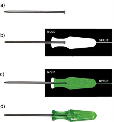
Injection over molding is a technology to join metal parts with polymers by polymer injection molding, several variants of this process exist. One of these variants is the metallic insert molding illustrated in Figure 2.6. Firstly, the metallic part (Figure 2.6-a) is placed into the injection mold cavity (Figure 2.6-b). Then molten polymer is injected over/around it (Figure 2.6-c). After cooling, the joining is achieved (Figure 2.6-d). The main joining mechanism is mechanical anchoring. Nevertheless, a possible adhesion between the parts is not discarded. Knifes and screwdrivers are examples of products manufactured by metallic insert molding process [60,61].
Figure 2.6 Illustration of the metallic insert molding process: metallic part (a), metallic part placed into injection mold (b), the mold is filled with molten polymer (c) and after the cooling the product is obtained (d). [Personal archive]
Injection over molding has been used in some industrial areas, such as in automotive [48].Currently, this technique has been used in automotive front-end modules [62], instrument-panels and bumper cross-beams, door modules, and tailgates [48,63]. The main advantages are the sealing, reduction of the number
a)
b)
c)
of components, high degree of automation and no further finish operations. However, restrictive features like complex design and large size reduce the application of the technique and it cannot be used for all thermoplastics due to the shrinkage behavior of the polymer materials in comparison with the metals [48,60,64].
2.2.4 Friction Riveting
Friction Riveting is a joining technique for polymer-metal hybrid joints developed and patented in Germany by Amancio et al. from the Helmholtz-Zentrum Geesthacht [8,65]. The development of the technique started with unreinforced thermoplastics joined with aluminium alloys in the mid 2000’s. Following that, the feasibility of new combinations of materials, such as fiber reinforced thermoplastics and thermosets joined with different metallic bolts [10-13,15] were addressed. It is assumed that friction-riveted joints have less stress concentration when compared to classical bolted connections due to the absence of a through-hole. Additionally, it does not need extensive surface preparation as adhesive bonding and the process time is fast in comparison with the two traditional techniques.
Figure 2.7 Possible Configurations of friction riveted joints. From the left to the right: metallic insert joint; overlap joint; sandwich type joint [9].
The Friction Riveting process is schematically shown in Figure 2.8for its basic joint configuration (“metallic insert joint”).
Figure 2.8 Simplified scheme of the Friction Riveting process for the “metallic
-insert joint” configuration: start position of the joining parts (a); rotating rivet is insert in the polymeric plate (b); deceleration and rivet forging (c) consolidation of the joint (d) [11].
polymers) or softening (in the case of amorphous polymers) of the polymer around and underneath the tip of the rivet due the local increase in temperature. The continuous force and rotational speed make the rivet penetrate deeper into the polymeric plate, expelling the molten/softened polymer as a flash (Figure 2.8 -b). The temperature at the tip of the rivet continues to increase. This occurs because the heat input becomes larger than the heat outflow due the low thermal conductivity of the polymer, thus generating a concentration of heat. At the end of the friction phase, the temperature at the tip of the rivet is high enough to plasticize it (the plasticized/softened state of the rivet is achieved in temperatures above 50% of the alloy melting point [22]) (Figure 2.8-c). At this point, the rotational speed is decreased to zero and the axial force is increased up to a pre-set value (the so called forging force is applied) or kept constant (forging force is absent). The plasticized tip of the rivet is deformed due to the opposite forces related to the colder polymeric volume, assuming a paraboloidal geometry with larger diameter and forming the anchoring zone. Then, the joint consolidates under pressure, since no forced cooling is applied (Figure 2.8-d) [8, 9,15].
Figure 2.9 Friction Riveting equipment (commercially available high-speed friction- welding spindle on automated structure with tri-axial force sensors and an integrated position sensor) available at Helmholtz Centre Geesthacht, Germany.
the tip of the metallic bolt. This parameter is related to the normal pressure distribution, rivet deformation and consolidation of the joint [9-12].
With the new available joining equipment (Figure 2.9), the process can be controlled either by or as a combination of time, force or spindle displacement; additional set-up parameters may be used to support process control, such as rotational speed and spindle-rotation angle. Taking into account the hardware improvements, a new variant of the process was introduced [15]. The new joining procedure was divided into two controlled steps. The first step is the friction phase. In this step the process was controlled by force and limited by displacement (position control) to avoid the complete perforation of the polymer composite plate and control indirectly the heat input. This means that the friction phase will finish when the spindle reaches the set displacement and rotation speed decreases to zero; at this point the second process step initiates. This step is represented by the final rivet forging and joint consolidation, whereas the axial force can be kept constant or increased (application of forging force); in this last step, the process is controlled by force and limited by time. This step is more adequate to be limited by time since the consolidation of the joint is dependent on the resulting cooling rate of the components, while the rotation has come to an end, thus reducing the risk of full penetration.
The new process parameter introduced in this process variant is Displacement at Friction (DaF). Axial force in the friction (Frictional Force, FF) and forging phases (Forging Force, FoF) is set in Newton instead of MPa (pressure unit) as force sensors allow for a more precise setup. The Displacement at Friction (DaF) is the spindle displacement during the friction phase. In the time-controlled process variant, Friction Time is responsible for controlling heat development and spindle displacement. Rivet penetration is variable and a more complex control of heat input is required to avoid base plate perforation. Therefore the new process parameter DaF provides a better control of rivet penetration.
The process starts in t0 when the rivet touches the polymer plate with a certain rotational speed and pressure (Friction Pressure). The course (straight line) indicates the spindle displacement. The frictional phase ends when the Friction Time (FT) is achieved. Then, the rotational speed is decreased to zero and, in this case, the pressure is increased (Forging Pressure). This pressure is relieved when the Forging Time (FoT) is achieved and the process is ended.
Figure 2.10 Typical FricRiveting monitoring curve [9] with process parameters and variables.
in the polymer and in the metal. The Frictional Torque (Mz) torque helps to estimate the energy input of the joints and can be correlated with the behaviour of the molten polymer and the plasticized metallic rivet [9,11,12].
The microstructural zones of friction-riveted joints were described for the first time by Amancio-Filho [66] using polyetherimide and AA2024-T351. Four microstructural zones were identified and described (Figure 2.11). Two affected zones were identified in the polymer: the polymer heat affected zone (PHAZ) and the polymer thermo-mechanically affected zone (PTMAZ). The other two zones were identified in the metallic joining part: the metal heat affected zone (MHAZ) and the metal thermo-mechanically affected zone (MTMAZ). The PHAZ and MHAZ are only affected by the heat generated. The PTMAZ and MTMAZ are affected by the heat as well as by the high plastic deformation imposed by the rivet movement along the process. Because of that, these zones are susceptible to metallurgical (in the rivet) and physicochemical (in the polymer) phenomena.
Figure 2.11 Representation of the four microstructural zones described in friction-riveted joints. Polymer heat-affected zone (PHAZ), polymer thermo-mechanically affected zone (PTMAZ), Metal heat-affected zone (MHAZ) and metal thermo-mechanically affected zone (MTMAZ). The Anchoring Zone (AZ) is also shown [66].
by the ratio between the width of the deformed rivet (W) and the penetration depth of the rivet (H); when W is greater than H is the reversal of the ratio. Friction riveted joints of polyetherimide (PEI) with aluminum alloy AA2024-T351 [65] and polycarbonate (PC) with aluminum alloy AA2024-T351 [10] showed an increasing trend on the ultimate tensile force when AR increases. However, with other combinations of materials the same behavior was not observed [11]. It seems that the simplified two-dimensional approach to calculate the efficiency is not applicable to all deformed rivet geometries. Thus, Blaga et al. [67] devised the volumetric ratio (VR) concept (Figure 2.12), which considers the interaction volume of the polymer that is above the deformed area of the tip of the rivet. VR is calculated using Equation 1, where H is the penetration of the metallic rivet, B is the height of the deformed tip of the rivet, W is the deformation of the metallic rivet and D is the original diameter of the metallic rivet. Recently, Altmeyer et al.
[12] proposed a third model named Mushrooming Efficiency. From ballistics, this two-dimensional method takes into consideration only the deformation of the tip of the metallic rivet. Besides being two-dimensional, the Mushrooming Efficiency is applied only to cases where the depth of penetration has no significant changes between the conditions examined [68]. This limits the use of this method and becomes invalid under conditions with high variations in the depth of penetration.
Figure 2.12 Simplified geometry of an insert type of friction-riveted joint used to calculate the Volumetric Ratio [67].
The types of failure of metallic insert type friction-riveted joints under tensile loading (T-pull testing) were described by Amancio-Filho et al. [69], as shown in Figure 2.13.
Figure 2.13 Friction-riveted joints failures under T-pull testing. The thicker red lines indicate the path of crack propagation upon final failure [69].
Figure 2.13-a shows a ductile fracture that occurred in the metallic rivet
outside of the polymer plate (“through the rivet”). This failure is the best in terms of joint strength since the maximum tensile strength of the joint is comparable to the maximum strength of the metallic rivet. Figure 2.13-b shows a fracture that occurred within the deformed tip of the rivet (“rivet pullout with back plug”). The rivet is pulled out from the polymer, leaving a part of the anchoring zone inside of the polymer plate. Figure 2.13-c shows a fracture that occurred around the
anchoring zone of the polymer (“full rivet pullout”). The rivet is completely
3 MATERIALS AND METHODS 3.1 Experimental Approach
This dissertation focused on the optimization of the FricRiveting process for aluminum alloy 6056-T6 and glass fiber reinforced polyamide 6 composite. For this purpose, the experimental approach of this research work was divided into four main phases, which are shown in Figure 3.1
Figure 3.1 Schematic illustration of the experimental approach.
In the second phase, the characterization of the joints was carried out. In this phase, the following investigations were carried out: determination of the physicochemical changes in the composite (ATR/FT-IR, DSC and dilute solution viscosity measurements), microstructural changes in the joining parts (LOM, SEM and EBSD), investigation of local (microhardness) and global (T-pull tensile testing and X-Ray radiography) mechanical properties and fracture analysis (SEM).
In the third phase, the relationships between FricRiveting conditions and joint properties were established. The influence of process parameters (RS, DaF and JF) on the responses process temperature, ultimate tensile force of joints and viscosity average molecular weight of PA6 and its significance were determined through analysis of variance (ANOVA) and RSM. Regression models were estimated and validated for the investigated responses.
In the fourth phase, the joint was optimized in terms of ultimate tensile force and its behavior after post-weld heat treatment, and natural weathering analyzed. The validated statistical models were used to achieve an optimized friction-riveted joint.
3.2 Base Materials Characterization
Figure 3.2 Base material: a) Metallic rivet of AA6056-T6 and b) Plate of polyamide 6 reinforced with short glass fiber.
Since there was little information on the base materials used, a preliminary characterization was performed.
In this study an AA6056-T6 solution heat treated and artificially aged extruded alloy is used for the rivets. The main microstructural characteristics of AA6056-T6 rivets used in this study were determined by optical microscope and are shown in Figure 3.3. Samples were prepared by longitudinal mid-sectioning of the rivet.
Figure 3.3 Longitudinal cross-section view of the microstructure of Aluminum alloy 6056-T6 rivets.
Table 3.1 Properties of AA6056-T6 as determined experimentally.
Properties Value
Density [g/cm³] 2.65
Ultimate tensile force [N] 5320 ± 102 Microhardness [HV 0.2] 139 ± 2
The physical-chemical properties of the PA6-30GF are shown in Table 3.2. Bulk density was measured by taking the weight to volume ratio of a composite plate. Thermal properties (Tc and Tm) and the degree of crystallinity were measured by differential scanning calorimetry (DSC). Total filler (glass fiber and carbon black) content was measured by ash content method based on ASTM D3171–99 standard [70].
Table 3.2 Properties of short glass fiber reinforced PA6 composite as determined experimentally
Properties Value
Bulk density [g/cm³] 1.38 Tc; Tm [°C] 185 ± 1; 215 ± 1 Crystallinity degree [%] 26.6 ± 0.73
Filler content [wt%] 32 ± 1
3.3 Friction Riveting Joining Equipment
3.4 Methods
3.4.1 FricRiveting Procedure
Prior to joining, the parts were cleaned to remove surface impurities like as dust or machining fluids. The rivets were cleaned with ethanol in an ultrasonic bath and the polymer composite plate was manually wiped with ethanol.
The joining procedure was divided into two controlled steps as described in Section 2.2.4. In the first step (the friction phase) the process was controlled by force and limited by displacement (position limited). The axial force was kept constant during the entire process; in other words a typical forging force higher than the friction force was not used. The theoretical forging phase (in some cases rivet may start deforming during the friction phase, as unpublished results have shown) and consolidation phase start in the second step when the rotation speed is stopped. In this last step, the process was controlled by force and limited by time.
3.4.2 Process Temperature Monitoring
Figure 3.4 Infrared thermo-camera positioning (a), Thermogram showing the maximum temperature of the softened composite flash being expelled out of the composite plate, the yellow rectangle is the measuring area selected for software evaluation (b); Evolution of the maximum temperature during the process measured by infrared thermography adapted from [15] (c).
3.4.3 X-Ray Radiography
X-ray radiography was performed according to the EN 1435 standard [71] while using a Seifert Isovolt 320/13 with a tube voltage of 60 kV and a tube current of 3.7 mA. The focus-to-film distance was 800 mm, and the focal spot was 1.5 x 1.5 mm. The joints were scanned with rays before mechanical testing. The X-ray images were measured using Image J software to reveal the real dimensions of the anchoring zone at the center of the joints as shown in Figure 3.5. Thus, the relation between volumetric ratio and ultimate tensile force could be investigated precisely.
Figure 3.5 X-ray image of a friction-riveted metallic-insert joint
3.4.4 Joint Microstructural Analyses
For microstructural investigations of the joined aluminum rivet, the grain structure was revealed using chemical etching with Airbus reagent (5 mL HF in 95 mL H2O and 10 mL H2SO4 in 90 mL H2O). Due to their different metallurgical transformations, to reveal the microstructure of the BM and TMHAZ, specimens were immersed in the reagent during 5 s, while for the MTMAZ during 15 s. Nonetheless, the chemical etching did not reveal clearly the grain structure in the MTMAZ. Thus, Electron Backscattered Diffraction (EBSD) was used to provide better understanding of the process-related microstructural changes in the metallic rivet, such as annealing phenomena (dynamic recovery and recrystallization). The EBSD analyses were carried out in a thermal emission gun scanning electron microscope (FEI Inspec S50, United States) operating at 25 kV.
For microstructural investigations of the polymer composite part, only LOM was used to investigate the presence of voids and some fiber orientation owing to the joining process. LOM was also used to analyze the interface between the metal and the polymer composite.
3.4.5 Local Mechanical Properties
Figure 3.6 Schematic view of the indents performed on metallic part of the joint (squares).
3.4.6 Physical- Chemical Changes in the PA6-30GF Composite
Differential Scanning Calorimetry (DSC) analysis was performed in a DSC Q2000 equipment (TA Instruments, United States) based on procedures described in [73] and in ASTM D3418-08 [74]. Aluminum crucibles were used. Samples weighing between 4.5 and 5 mg with precision of ± 0.01 mg were extracted from the PTMAZ. Samples were submitted to a heating-cooling cycle in the range from 30 to 270 °C at heating rate of 10 °C min-1 under nitrogen flow of 50 mL min-1. This procedure were applied to determine the melting enthalpy
(ΔHm), as well as the melting (Tm) and crystallization (Tc) temperatures for the composite thermo-mechanically affected (CTMAZ) zone as well for the base material.
The degree of crystallinity (%𝐶) of the PA6 samples was calculated using the Equation 2 [75].
%𝐶 =
∆𝐻𝑚∆𝐻°𝑚(1−𝑊𝑓)
(2)
Dilute solution viscosity measurement was employed to determine the viscosity average molecular weight of polyamide 6 and then to characterize the extension of PA6 degradation caused by the FricRiveting process. Samples were taken from the flash material expelled during the process. Samples from the base material were also analyzed for comparison. The procedure was based on the ASTM D2857 standard [76] along with a methodology developed by the author [77]. The samples were properly weighed, dissolved in 85 % formic acid and filtered through a PTFE membrane (average pore size of 0.2 m) to separate the polymer solution from the filler (glass fiber and carbon black). The weighting procedure took into account the PA6-30GF composition (32 wt% filler content; see Table 5.2) in order to obtain a PA6 solution with final concentration of 0.1 g/dL. After complete solubilization and filtration, the PA6 solution was placed in an Ubbelohde viscosimeter type 1 immersed in a bath with temperature controlled at 25 ± 0.1 °C. The intrinsic viscosity values were determined by the single point method of Billmeyer [78], which consists in determining the intrinsic viscosity using a single polymer solution concentration through the Equation 3:
[𝜂] = (0.25 ∙ 𝜂𝑟𝑒𝑑) + (0.75 ∙ 𝜂𝑖𝑛𝑒𝑟) (3)
where [𝜂] is the intrinsic viscosity, [𝜂𝑟𝑒𝑑] is the reduced viscosity and [𝜂𝑖𝑛𝑒𝑟]is the inherent viscosity.
The viscosity average molecular weight (Mv) of the polyamide 6 was
calculated by the Mark-Houwink-Sakurada approach (Equation 4):
av M
K
(4)where [𝜂] is the intrinsic viscosity and the constants
K
= 2.26x10⁻⁴ dL/g and a = 0.82 [79].evaluate the degradation level of the PA6 caused by the FricRiveting process. Samples were extracted from the flash material expelled during the joining. All spectra were acquired with 100 scans, resolution of 4 cm-1 and spectral range of 4000 to 500 cm-1.
3.4.7 Polyamide 6 Composite Integrity
Optical microscopy was used to analyze the breakage of the fibers in the PA6-30GF composite caused by the FricRiveting process. The samples were taken from flash expelled during the process and from the base material for comparison. The lengths of the glass fibers were determined by use of image analyzer software (Image J software). The glass fibers were recovered from the separation procedure described in Section 3.4.6. The fibers were distributed over a glass plate with the aid of a 1:1 solution of distilled water and ethanol and then left to a hot plate until the complete evaporation of the solution. Around 1000 fibers were counted for each condition following the approach reported in [80-82]. The number average length (𝑙𝑛), the weight average length (𝑙𝑤) and the polydispersity index (P) of the glass fibers were calculated using Equations 5, 6 and 7, respectively, where (𝑛𝑖), is the number of glass fibers with length li and
∑𝑁𝑖=1𝑛𝑖 = 𝑁 is the total number of glass fibers.
𝑙
𝑛=
∑𝑁𝑖=1𝑛𝑖∙𝑙𝑖∑𝑁𝑖=1𝑛𝑖
(5)
𝑙
𝑤=
∑𝑁𝑖=1𝑛𝑖∙𝑙𝑖2∑𝑁𝑖=1𝑛𝑖∙𝑙𝑖
(6)
𝑃 =
𝑙𝑤𝑙𝑛
(7)
int 2 f c D L
(8)
where:
L
is the length of the fiber,D
is the diameter, f is the tensile strengthof the fiber and is
int interfacial shear stress. The value of
int can beapproximated to the value of the shear stress of the polymer matrix by assuming that there is perfect adhesion between the fiber and the polymer. Taking into account that the shear stress values for PA66 are around 45 MPa [80] and considering a typical value for the fiber strength of 1500 MPa [80], it results that the critical fiber aspect ratio is 16.7. Considering that average glass fiber
diameter is 10 μm, hence, the critical fiber length for the effective reinforcement of the PA6 used in this work is 167 μm.
3.4.8 Quasi-Static Global Mechanical Performance
Tests were performed on T-Pull tensile specimens [65] (Figure 3.7-a) in a universal testing machine Zwick/Roell equipped with a load cell of 100 kN with crosshead speed of 1 mm.min-1 at room temperature (21 °C). The sample holder for the T-pull tests is schematically illustrated in Figure 3.7-b.
Figure 3.7 T-Pull AA6056/PA6-30GF specimen (a) and Schematic representations of the joint sample holder (b) [84].
Scanning electron microscopy (SE-SEM, model Quanta FEG 650, FEI, USA) was carry out under secondary electrons detection mode to observe the joint fracture surfaces. The selected fractured joints were sputtered with gold. SEM analysis was performed at 5 kV; working distance of 19.5 mm for the composite part and 15 mm for the metallic part; atmosphere pressure of 0.001 Pa. This technique helped to evaluate the types of fracture micromechanisms (e.g. ductile or brittle behavior) that occurred on the tested joints.
3.4.10 Effect of Process Parameters on Joint Properties
The process parameters used in this work were Rotational Speed (RS), Displacement at Friction (DaF), Joining Force, JF (Friction Force equal to Forging Force), and Forging Time (FoT). The range and level of each parameter is shown in Table 3.3. The Forging Time (FoT) was kept constant at 3 s since this parameter did not affect the anchoring zone formation. The value of the FoT was selected from preliminary feasibility studies.
Table 3.3 Parameters range used to obtain the AA6056-T6/PA6-30GF joints. Process parameters
Levels Rotational Speed [rpm]
Displacement at Friction [mm]
Joining Force [N]
Minimum (-1) 14000 8 1600
Maximum (+1) 16000 10 2200
considered statistically significant using 95 % of confidence interval (α=0.05) and slightly statistically significant using 90 % of confidence interval (α=0.1).
Table 3.4 Combinations of parameters resulted from the BBD for the AA6056-T6/PA6-30GF friction-riveted joints.
Process parameters Conditions designation Rotational Speed [rpm] Displacement at Friction [mm]
Joining Force [N]
C1 16000 10 1900
C2 15000 8 1600
C3 14000 9 1600
C4 15000 8 2200
C5 14000 9 2200
C6 14000 8 1900
C7 14000 10 1900
C8 15000 10 2200
C9 15000 9 1900
C10 16000 9 1600
C11 15000 9 1900
C12 15000 10 1600
C13 16000 9 2200
C14 16000 8 1900
C15 15000 9 1900
Regression models for the responses were obtained with Minitab and Statistica software. The regression models were reduced considering only the statistically relevant factors determined from ANOVA tables. The reliability of the models was evaluated using the adjusted coefficient of determination, R2adj. The correlation of predicted data by the model with experimental data is considered very good when the value of R2adj is near to 1.
3.4.11 Post Joining Heat Treatment
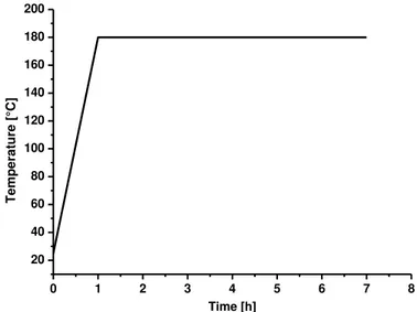
aluminum [92] Based on that, a PJHT was performed to improve the global mechanical property of the optimized joint (C13). The PJHT used was the artificial aging treatment selected from literature [93]. An example of PJHT diagram in this work is shown in Figure 3.8. A set of joints was heated in an oven (P330 from Nabertherm-GmbH) from 20 oC up to 180 °C at 150 oC h-1 and kept at this temperature for 6 hours. Afterwards, the joints were cooled outside of the oven to room temperature (23 °C). After 72 hours these joints were submitted to T-pull tensile testing. The joints were weighted before and after the test to obtain the water uptake during the PJHT. Microhardness on the metallic part and DSC of the polymer composite were performed to better understand the effect of PJHT on the local mechanical properties and polymer degree of crystallinity.
Figure 3.8 Example of a post-joining heat treatment cycle used to treat a selected set of friction riveted joints (conditions C13).
3.4.12 Natural Weathering
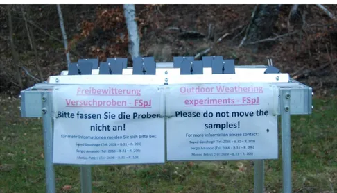
The natural weathering tests were performed on a set of joints at HZG for a testing times of 6 and 12 months to evaluate the effect of environmental conditions (i.e. ultraviolet (UV) radiation, humidity, temperature, pollutants, and other factors) on the ultimate tensile force. Figure 3.9 shows the testing jig where the tests were conducted based on ASTM D1435-13 [94]. The joints were weighted before and after the test to obtain the water uptake during the natural weathering. Dilute solution viscosity measurements were performed on polymer taken from the flash of these joints to analyze the extension of degradation. The
0 1 2 3 4 5 6 7 8
weathering data were obtained online at Weather Undergroung (https://www.wunderground.com/). Detailed data for the Geesthacht weather in the period of the experiments is shown in Appendix A.
4 RESULTS AND DISCUSSION
4.1 General Aspects of Joint Formation in Friction Riveting
Friction-riveted joints were produced using two-process phases described in Section 3.4.1. Figure 4.1shows an example of the process monitoring diagram for the FricRiveting joining cycle with this process variant for the joint produced with condition C13 (Table 3.4). For this condition the rotational speed was set to 16000 rpm, displacement at friction to 9 mm and joining force to 2200 N. The forging phase (second phase) had the duration of 3000 ms (FoT= 3000 ms). This condition was selected because combines a high shear (higher value of rotational speed) with a high strain rates (higher value of joining force). The following sections describe the positive effect of it on the heat generation, anchoring zone formation and global mechanical properties.
Figure 4.1 Process monitoring diagram for condition C13 (RS: 16000 rpm, DaF: 9 mm, JF: 2200 N).
The process temperature for the BBD conditions showed a wide spread difference between the minimum and maximum measured values and it had direct influence on the formation of the anchoring zone. Figure 4.2 shows the process temperature and volumetric ratio for the joints produced with fifteen BBD conditions. In terms of process temperature the minimum value was 323 °C for condition C3 and the maximum value was 399 °C for condition C13. In terms of
anchoring efficiency the minimum value for volumetric ratio was 0.35 for condition C3 and the maximum value was 0.72 for condition C13.
Figure 4.2 Maximum temperature and volumetric ratio for the joints produced with fifteen BBD conditions.
Figure 4.2shows that process with low temperatures generated joints with low anchoring efficiency. The level of deformation is related to the heat generated during the process which follows the Equation 9 [95]:
𝑄
𝑡𝑜𝑡𝑎𝑙= [(
𝑙
𝑙
𝑤𝑛
∗ 𝜇 ∗ 𝑃
(𝑟)) +
𝜂 ∗ 𝑉
𝑚𝑎𝑥𝐻
] ∗ 𝑉
𝑚𝑎𝑥(9)
Where: Qtotal is the total heat input in the joint area, µ the kinematic friction
coefficient, P(r) the normal pressure distribution on the tip of the rivet, η the
molten polymer viscosity, Vmax the maximal tangential speed of the rivet obtained from the angular speed (w) and the radius of the original rivet (R): w = Vmax/R, and H the average width of the consolidated polymeric layer. This equation considers that the heat input is generated mainly by friction; in thermoplastics it is related to viscous dissipation (internal shearing in the molten polymer) [95].
Table 3.4). The joints in Figure 4.3-a, Figure 4.3-b and Figure 4.3-c were obtained with a low (C3), medium (C9) and high (C13) heat input respectively.
Figure 4.3 Cross section of AA6056-T6/PA6-30GF joints – selected conditions: C3 (RS = 14000 rpm, DaF = 9 mm and JF = 1600 N) (a), C9 (RS = 15000 rpm, DaF = 9 mm and JF = 1900 N) (b) and C13 (RS = 16000 rpm, DaF = 9 mm and JF = 2200 N) (c).
The maximum temperatures achieved for these conditions were C3 = 323 °C, C9 = 342 °C and C13 = 399 °C. Therefore, the deformation on the tip of the metallic rivet is greater for joints with a higher heat input. This occurs because higher temperatures lead to larger plasticized volumes at the tip of the metallic rivet, thus resulting in a greater deformation.
4.2 Process-Related Changes in the Materials Joined by Friction Riveting
Figure 4.4 Microstructural zones of a FricRiveted AA 6056-T6/PA6-30GF joint C13 (16000 rpm, 9 mm and 2200 N).
4.2.1 Changes in the Metallic Part of Friction-Riveted Joints
phenomenon to occur at high temperatures (usually process temperature higher than 50 % of the alloy melting temperature) and higher shear rates (10-1-10-3 s-1) [96]. In the MHAZ, no microstructural change in comparison to the base material (Figure 3.3) has been observed by LOM. However, the temperature achieved within this area may induce microstrutural changes that are only visible using a transmission eletron microscope, such as static recovery and solubilization of the precipitates [10,84].
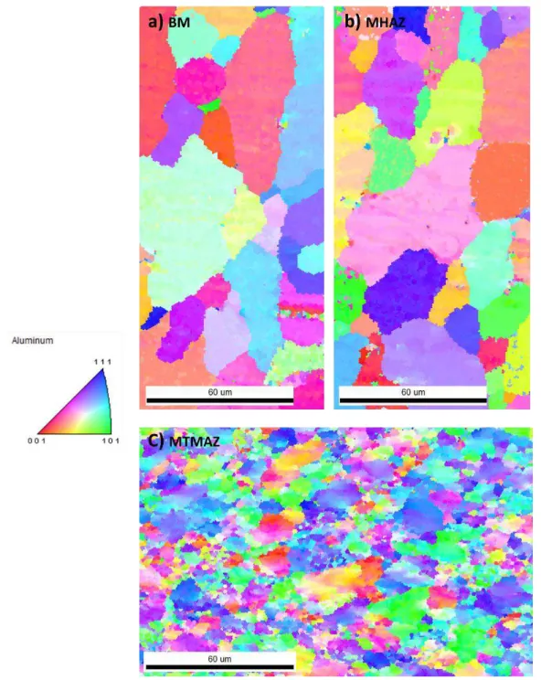
Figure 4.5 Microstructural zones of a friction-riveted AA 6056-T6/PA6-30GF joint C13 (16000 rpm, 9 mm and 2200 N) (a); Detailed microstructural zones of
joint’s metallic rivet: Detail of the Heat Affected Zone of the metal, MHAZ (b); Thermo-Mechanically Affected Zone of the metal, MTMAZ (c), and the realignment of the grains in the direction of the material flow in the bottom of MTMAZ (d).
4.6-b) and MTMAZ (Figure 4.6-c) in the metallic rivet of joint condition C13. The grains were colored according to their crystallographic orientation. In Table 4.1 the fractions of low angle boundary (LAB) for each area is presented.
Table 4.1 Fraction and low-angle boundaries of regions shown in Figure 6.6.
Region LABs (2-15°) [%]
Covered area [µm2]
Base material 49.1 14104
MHAZ 45.2 14924
MTMAZ 62.5 16720
Comparing Figure 4.6-a, b and c the assumption from the LOM observations can be validated. No relevant differences between BM and MHAZ are observed while partial grain refinement can be also observed on MTMAZ due to the plastic shear deformation and high process temperatures. The percentage of LAB increased in the MTMAZ in comparison to the BM; this indicates that dynamic recrystallization may be occurring in this region [96, 97].
Figure 4.7 Microhardness map: Base material (a) and Condition C13 (16000 rpm, 9 mm and 2200 N) (b).
A significant decrease in the microhardness of the rivet before and after the FricRiveting process can be observed in Figure 4.7. In the MTMAZ (Figure 4.7b) the microhardness decreased by 40 % compared with the base material. In the MHAZ (Figure 4.7b), the decrease in microhardness is smaller (21 %). In the case of AA6056-T6, the main factor that affects the strength/hardness is the presence of precipitates. The base material used is already artificially heat treated (T6), whereby the precipitates are already in the aluminum matrix helping with the alloy strengthening. For AA6XXX, a decrease in hardness has been reported for other friction-based joining process, such as friction stir welding [93,98,99]; hardness undermatching has been reported to be associated with the dissolution of precipitates as a result of high process temperatures and strain rates. As discussed earlier other annealing phenomena such as, dynamic recovery and recrystallization might be also occurring as indicated by the microstructural changes shown in Figure 4.6.
3Y) [100]; therefore a decrease in the hardness implies a the decrease of the local joint strength. This will be further discussed in Section 4.3.
4.2.2 Changes in the Polymer Composite Part of Friction-Riveted Joints
4.2.2.1 Defects in the Polymer Composite Affected Zones
The FricRiveting is a severe thermo-mechanical process to the polymeric part because of the high heat generated and shearing imposed by the rivet during the process. Figure 4.8 shows the thermo-mechanically affected zone of the polymer composite (abbreviated as “CTMAZ” to differ from the PTMAZ for unreinforced polymer) on the region 1 of Figure 4.5.
Figure 4.8 Detail of the composite thermo-mechanically affected zone (CTMAZ) showing the presence of voids (marked with arrows) in the CTMAZ and in the interface with the CHAZ.
can be related to the process-related evolution of water and additives of the polymer matrix, and partial thermos-mechanical degradation of the matrix [28].
Apart from being formed by the phenomena previously described, the voids at the interface of the CTMAZ and CHAZ may be generated due to the interaction between the molten composite and the rotating rivet. This interaction is known as the Weissenberg effect [101] and it occurs due to the elasticity of the fluids. This effect of elasticity is generated during shear flow because of normal stresses [102-104]. Basically, this phenomenon is observed when a spinning rod is inserted into a solution of non-newtonian fluid. Instead of being thrown outward like in newtonian fluids (Figure 4.9a), the solution climbs the rod due to the positive normal force (Fn) (Figure 4.9b).


![Figure 2.10 Typical FricRiveting monitoring curve [9] with process parameters and variables](https://thumb-eu.123doks.com/thumbv2/123dok_br/15915774.674369/51.892.283.641.366.716/figure-typical-fricriveting-monitoring-curve-process-parameters-variables.webp)