INTUMESCENT FIRE PROTECTION OF CELLULAR BEAMS
Luis Mesquitaa,*, João Gonçalvesa, Gustavo Gonçalvesa, Paulo Pilotoa, Kada Abdelhakb
aPolytechnic Institute of Bragança, Portugal
bFaculty of Civil Engineering and Arch., Hassiba Benbouali University of Chlef, Algeria
Abstract: Cellular beams are structural steel beams that are deeper than normal rolled sec-tions and have holes cut into their webs. As the web post failure may occur before the section reaches the limiting temperature usually an increase in the fire protection may be required for members with web openings in comparison to its equivalent solid section.
The aim of this work is to present an experimental study of unloaded solid and cellular beams with circular holes in fire conditions with and without intumescent fire protection. These pre-liminary tests are the basis for generating an elemental multi-temperature analysis (EMTA) needed to assess cellular beams with intumescent protection as prescribed by the prEN13381-9.
1.
Introduction
Cellular beams are widely used in multi-storey buildings, especially to achieve long spans and the same time providing passage for ducts, cables and other technical installations. These beams are steel sections with distributed circular openings that are produced by cutting and welding hot rolled steel sections (Westok method). The split halves are then offset and welded together to form a deeper beam with full circular or hexagonal shaped web openings. A dif-ferent method, the Fabsec method, consists on cutting circular openings in a steel plate and the cellular beams are fabricated from welding three fabricated steel plates.
Fig. 1: The cutting process of cellular beams. The use of cellular Beams in buildings, [2].
For a beam with web openings at a design degree of utilisation, web post failure may occur before the section reaches the critical temperature of members in bending. This is due to the fact that the temperature of the web-post in a cellular beam increases at a faster rate compared to its equivalent (similar web size) solid beam. If the temperature of the web-post increases faster than expected than the cellular beam failure may occur by local buckling instability of the web-post between the openings or the Vierendeel bending at the opening [3]. In a fire sit-uation the elastic modulus of steel reduces rapidly in comparison to its strength, which results in more rapid reduction of capacities based on buckling than those based on strength. Hence the buckling capacity of web-posts reduces more rapidly with temperature than those based on other failure types. Therefore web-post buckling tends in general to be the critical mode of failure in fire, even for beams with low web slenderness (d/t) ratios, [4].
To avoid this premature collapse, in relation to the behaviour of equivalent solid beams, when a fire protection is used, an increase in the fire protection thickness may be required for mem-bers with web openings.
Traditionally the design guidance “Fire Protection for Structural Steel in Buildings” from the Association for Specialist Fire Protection (ASFP), known as the ‘Yellow Book’, until its 3rd edition from the [5] indicates that a 20% increase in thickness of passive fire protection mate-rial should be used for members with web openings (the 20% being 20% increase in thickness from that required for the solid section). This 20% rule is for passive fire protection thickness, and has therefore been widely used for intumescent coating thickness (DFT) on cellular beams as their use has increased.
calculated for each web post width. This data allows to draw a regression line of the ratios in function of web post widths and the failure temperature is converted to the required protection thickness using the multi-temperature loading tables defined for different fire resistant times and sections factors of the beam taken as 1400 divided by the web thickness.
After a great effort from the coatings manufactures to produce the DFT tables for cellular beams, and with the used of beams with rectangular and elongated holes, a more general pro-tocol (engineering based) was established valid for rectangular and oval holes. This does not require the loaded beam to be tested and the major difference is that the web post tempera-tures are compared to the temperature of a plain web, instead of the bottom flange, [9]. This assessement procedure was also on the basis for the establishment of the European standard prEN13381-9 [10].
2.
Assessment of cellular beams protected with intumescent coatings
The questions raised about the temperature of the web post being higher than a similar solid beam motivated the need of further experimental fire tests. These were mainly conducted by the coatings manufactures due to their necessity to supply their own loading tables, and its results were kept confidential.
The published work of Bailey about experimental fire resistance tests of unloaded solid and cellular beams showed that on beams without fire protection the flange and web post tempera-tures of the cellular beams were slightly lower than the corresponding temperatempera-tures of the sol-id beams [11]. The author justifies that this behaviour can be due to the influence of the flow of hot gases in the furnace.
Also the same author perform a set of fire resistance tests on unloaded solid and cellular beams, with circular holes, protected with intumescent paint. The results comparison shows that, in all the tests, the temperatures in the web post and flange temperatures were higher in the cellular beam than the corresponding temperatures of the equivalent solid beams. The au-thor justifies this difference due to intumescence shrinkage around the circular hole perimeter, but he also refers the lack of protection within the holes, consistent with a deficient coating [12]. The results show that the difference between the web post and bottom flange tempera-tures depends on type and thickness of the intumescent fire protection.
It is recognised that the intumescent fire protection thickness required to provide a given fire resistance to a cellular beam depends on its web thickness, the hole shape and dimensions, the width of the web post, the degree of the beam asymmetry and the structural utilisation factor, as well as the protection efficiency of the intumescent coating, [8].
3.
Test Programme
The set of experimental tests performed at the Polytechnic Institute of Bragança to evaluate the behaviour of solid and cellular beams with and without fire protection is the presented in Table 1. The table shows the set of performed experimental tests considering solid beams with and without intumescent protection and also cellular beams with and without intumescent fire protection. The aim was to consider for all tested beams the same nominal intumescent DFT, equal to 1000 [m], but as can be seen in the table the coating of the test P4 has resulted in a little higher DFT. A water based intumescent coating supplied by International Coatings was used. Also were studied different combinations of the hole diameter and web post widths. All the sections are made from hot rolled IPE220 steel profiles with 600 [mm] length and in case of the cellular sections the circular holes cutted directly from the web, resulting in a sec-tion with the same high, as represented in the Fig. 2.
Table 1: Geometries and properties of the tested beams.
Ref. Beam type [μm] DFT Hole Diameter[mm] Web post [mm] W/D
P1 Solid - - - -
P3 Solid 1047,3 - - -
P4 Solid 1187,5 - - -
P5 Cellular - 120 60 0.5
P9 Cellular - 120 75 0.625
P12 Cellular - 160 80 0.5
P13 Cellular 993,7 160 80 0.5
P15 Cellular - 160 100 0.625
P16 Cellular 943 160 100 0.625
Fig. 2: Dimensions of the tested solid and cellular beams
4.
Experimental setup and element instrumentation
The fire resistance tests were performed on a fire furnace with interior dimensions of 1x1x1 [m3], insulated with refractory bricks and ceramic fibber. It is a gas furnace with four gas
160
D+W
L-D-W-160
L=600
D
220
w
D
D
D=120 [mm]
D=160 [mm]
L=600
EN1363-1 (CEN, 1999) and is controlled by a plate thermocouple.
For the analysis of the steel temperature evolution several thermocouples type K were used as recommended by the standard prEN13381-9 [10], positioned and numbered as shown in Fig. 3. Two types of type K thermocouples were used. For the case of unprotected beams the thermocouples wires were welded to the steel surface, but for the sections with fire protection, the thermocouples were installed after coating the steel member and mineral insulated ther-mocouples with Inconel sheath were used by means of a drilled hole of 1.5 [mm]. By this procedure it was wanted to minimize the influence of the thermocouple wires on the coating expansion and therefore on the fire protection efficiency.
Fig. 3: Position and numbering of the thermocouples.
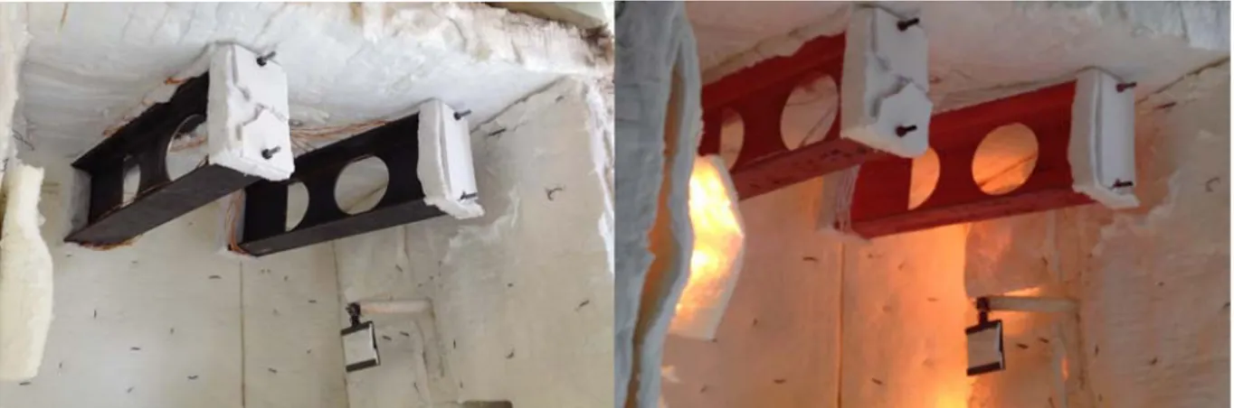
The protected and unprotected sections were placed with the top flange fixed to the furnace roof and with a ceramic mat layer of 50 [mm] in-between, simulating in all the cases a fire exposure by three sides. Also the beams ends were also insulated by an equivalent ceramic mat to avoid the heat transfer from the ends, as can be seen in Fig. 4 and Fig. 5, for unprotect-ed and protectunprotect-ed beams, respectively.
Fig. 4: Tests P12 and P15 before and after the test.
120 120 120 120 120
26 26 26 26 160 D+W L-D-W-160 L=600 D 22 0 w
D D=120 [mm] D=160 [mm]
Fig. 5: Tests P4 and P3 before and after the test.
5.
Temperature results of protected and unprotected sections
The steel temperature evolution of the tests were measured by the attached thermocouples. The flange temperature is determined by the thermocouples T9 to T12 and the web post tem-peratures by the thermocouples T1, T2 and T3. The data obtained from T7 and T8 can be used to verify the non-uniform temperature distribution across the section due to the three side fire exposure. During the test some of the thermocouple temperatures presented some unrealistic fluctuations, possibly due to an intermittent contact to steel and as a consequence were disre-garded from the following graphs and analysis.
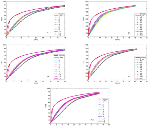
The temperature results from the unprotected solid and cellular beams are presented in Fig. 6.
Considering for comparison the results of the tests P1 and P9, a solid and a cellular beam test-ed simultaneously, one can compare the evolution of the mean temperature of the web post temperature (WT) and the mean flange temperature (FT), presented in Fig. 7. In both ele-ments, the temperature of the cellular beams in smaller than its equivalent solid beam.
Fig. 7: Evolution of the mean temperature registered on the web post and flanges of test P1 and P9.
For the case of solid (P3 and P4) and cellular beams (P13 and P16) tested with intumescent fire protection, the temperature evolution is presented in the Fig. 8. The curves present an higher non-uniformity of the temperature in the elements, when compared to the unprotected beams.
Fig. 8: Temperature evolution results of intumescent protected solid and cellular beams.
Considering the global mean temperature of the beams, the time to reach a temperature of 550 [ºC] is 36 and 49 minutes for the solid beams P3 and P4, respectively, but for the cellular beams P13 and P16 the time decreases significantly to 28 minutes in both beams.
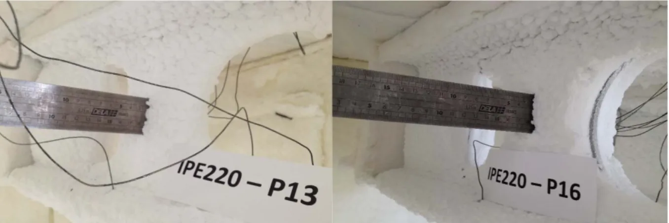
85 [mm] and 75 [mm], respectively. The intumescent char expansion of both beams is shown in Fig. 9.
Fig. 9: Intumescent coating expansion of test P13 (left) and P16 (right) after test.
6.
Conclusions
This work presents the results of a set of experimental tests on protected and unprotected solid and cellular beams subjected to a fire exposure on three sides. The parametric analysis allows comparing the performance of an intumescent coating as a fire protection material using beams with and without intumescent protection. Additionally, it is also studied the effect of intumescent thickness, the hole diameter and the web post width in the case of cellular beams. The experimental tests are carried out with reference to the standards EN13381-8 for solid beams protected with intumescent paint and prEN13381-9 for the analysis of cellular beams protected with intumescent paint.
The experimental temperature results show intumescent coating efficiency when applied to solid beams and also for cellular beams, resulting from its application an increase fire the re-sistance time in both cases. Considering for example the time required for the steel to reach 550 [ºC], with the application of a nominal thickness of 1000 [m], an increase of the fire re-sistance time of 25 minutes is achieved for solid beams, while for cellular beams with a hole diameter of 160[mm] the increase is equal to 17 minutes.
Tests performed in cellular beams with web posts of 80 and 100[mm] does not show any sig-nificate temperature difference neither in relation to the fire resistance time. For both beams, when is applied a nominal DFT equal to 1000 [m], the temperature of 550 [ºC] is achieved after 28 minutes. For longer fire exposure periods a slight difference can be already verified. For the case of a cellular beam with intumescent coating, test P16, a small contraction of the intumescent char around the circular hole, leaving a small area of steel directly exposed to fire.
This study is being extended to a wider parametric analysis considering different cellular beams geometries and intumescent coatings thicknesses to allow for a general elemental mul-ti-temperature analysis (EMTA).
Acknowledgments
References
[1] Pachpor, P.D., et al., Finite Element Analysis and Comparison of Castellated and Cellular Beam. Advanced Materials Research, 2011. 264-265: p. 694-699.
[2] TATASteel and BCSA, Steel Construction Fire Protection, ed. B.A. Barrett. 2013.
[3] Wang, P., et al., Web-post buckling of fully and partially protected cellular steel beams at elevated temperatures in a fire. Thin-Walled Structures, 2015.
[4] Wong, V.Y.B., I.W. Burgess, and R.J. Plank, Behaviour of composite floor beam with web openings at high temperatures, in SDSS’Rio 2010 STABILITY AND DUCTILITY OF STEEL STRUCTURES, P.V. E. Batista, L. de Lima (Eds.), Editor. 2010: Rio de
Janeiro, Brazil, .
[5] ASFP, Fire Protection for Structural Steel in Buildings (The Yellow Book), 3th Edition revised Jan 2004. 3th Edition ed. 2004: ASFP - Association for Specialist Fire
Protection.
[6] Nadjai, A., et al., Performance of cellular composite floor beams at elevated temperatures. Fire Safety Journal, 2007. 42(6-7): p. 489-497.
[7] SCI, Structural Fire Design: Off-site Applied Thin Film Intumescent Coatings (Second Edition), L.C. Newman, J.J. Dowling, and W.I. Simms, Editors. 2005: Ascot.
[8] ASFP, Fire Protection for Structural Steel in Buildings (The Yellow Book), 4th Edition revised 24 Aug 2010. 2010: ASFP - Association for Specialist Fire Protection.
[9] ASFP, Fire Protection for Structural Steel in Buildings (The Yellow Book), 5th Edition revised Jan 2014. 2014: ASFP - Association for Specialist Fire Protection.
[10] CEN, prEN 13381-9: Test methods for determining the contribution to the fire resistance of structural members Part 9: Contribution of fire resistance to steel beams with web opening. 2013, European Committee for Standardization: Brussels, Belgium.
[11] Bailey, C., Indicative fire test on a cellular and solid web steel beam. 2003,
Manchester Centre for Civil and Constructional Engineering: Manchester
[12] Bailey, C., Indicative fire tests to investigate the behaviour of cellular beams protected with intumescent coatings. FIRE SAFETY JOURNAL, 2004: p. 689-709.
[13] CEN, EN13381-8 Test methods for determining the contribution to the fire resistance of structural members. Part 8: Applied reactive protection to steel members. 2010,
![Fig. 1: The cutting process of cellular beams. The use of cellular Beams in buildings, [2]](https://thumb-eu.123doks.com/thumbv2/123dok_br/16865914.753993/2.892.105.789.107.353/fig-cutting-process-cellular-beams-cellular-beams-buildings.webp)