Numerical Modelling of Steel Beam-Columns in Case of Fire
-Comparisons with Eurocode 3
Vila Real, P. M. M. a., Lopes, N. b, Simoes da Silva, L. c, Piloto, P. d, Franssen, J.-M. C
n, b Department of Civil Engineering, University of Aveiro, 3810 Aveiro, Portugal
Tel.: +351-234-370049; fax: +351-234-370094; e-mail: [email protected]
*
Corresponding authorc Department of Civil Engineering, University ofCoimbra, 3030-290 Coimbra
d Department of Mechanical Engineering, Polytechnic ofBraganc;;a, Braganc;;a, Portugal
C Department M&S , University of Liege, Liege, Belgium
ABSTRACT
This paper presents a nllmerical study of the behaviour of steel/-beams subjected to fire
and a combillation of axial force alld bending moments. A geometrical and material
lion-linear fillite element program. specially established in Liege for the analysis of
stmctures submitted to fire. has been used to determille the resistance of a
beam-column at elevated temperature. using the material properties of Eurocode 3. part 1-2.
The numerical resul!s have beell compared with those obtained with the Eurocode 3.
part 1-2 (1995) and the new version of the same Eurocode (2002).
The results hmJe confirmed that the Ilew proposal for Eurocode 3 (2002) is more
consel1Jative thallthe ENV-EC3 (1995) approach.
Key words: beam-column, buckling, torsional-buckling, fire, Eurocode 3, numerical
NOMENCLATURE
A Area of the cross-section
E Young' s modulus of elasticity
I v
Yield strengthK Stiffuess of the spring
K " Axial stiffuess of the beam
K ,'0 Axial stiffness of the beam at room temperature
k" 0 Reduction factor for the yield strength at temperature B a
k",o
Reduction factor for the slope of the linear elastic range at temperatureB.
M ~.IF1R Buckling resistance moment in the fire design situation given by SAFIR
M" ,ji,"d Design bending moment about y axis for the fire design situation
M ,".ji,O.Rd Design moment resistance about y axis of a Class 1 or 2 cross-section with a
uniform temperature 0 a
N ji.lld
N ji ,n ,Rd
Design axial force for the fire design situation
Design axial force resistance with a uniform temperature 0.
Elastic section modulus in y axis
Plastic section modulus in y axis
Greek
Imperfection factor and thermal elongation coefficient of steel
is the equivalent uniform moment factor corresponding to lateral-torsional
P M ,! , Is the equivalent uniform moment factor for the y aXIS, In this case
(
p"")'
= 1.1)Y MO Partial safety factor (usually YM O = 1,0)
Y At ,ft Partial safety factor for the fire situation (usually Y "' .ft
=
1.0 )X
LT Non-dimensional slenderness for lateral-torsional bucking at roomtemperature
A,. Non-dimensional slenderness of the y axis for flexural buckling at room
temperature
A_ Non-dimensional slenderness of the z axis for flexural buckling at room
temperature
ALT ,{/ Non-dimensional slenderness for lateral-torsional buckling at temperature
A,..n Non-dimensional slenderness of the y aXIS for flexural buckling at
temperature
eo
A" O Non-dimensional slenderness of the z aXIS for flexural buckling at
temperature
eo
X LT,ji
X min.fi
Reduction factor for lateral-torsional buckling in the fire design situation
Is the minimum reduction factor of the y and z axis for flexural buckling in
the fire design situation
X )'.ft Is the reduction factor of the y axis for flexural buckling in the fire design
situation
X ' ,}i Is the reduction factor of the
z
axis for flexural buckling in the fire designI . INTRODUCTION
Under fire conditions, axially and eccentrically loaded columns were studied by
Franssen et al [1-3] for the cases where the failure mode is in the plane of loading, who
proposed a procedure for the design of columns under fire loading, later adopted by
EC3 [4]. Analogously, Vila Real et al [5-7] studied the problem of lateral torsional
buckling of beams under fire loading, and equally proposed a design expression also
adopted by EC3 [4].
The 3D behaviour of members submitted to combined moment and axial loads, i.e.
the interaction between bending, buckling and lateral torsional buckling, was never
specifically studied and it is thus impossible to establish the level of safety and accuracy
provided by the current design proposals. It is the objective of the present paper to
address this issue, using a numerical approach.
2. NUMERICAL MODEL
2. 1 Basic Hypothesis
The program SAFIR [8] was chosen to carry out the numerical simulations, which is
a finite element code for geometrical and material non-linear analysis, specially
developed for studying structures in case of fire. In the numerical analyses, a
three-dimensional (3D) beam element has been used. It is based on the following
fo rmulations and hypotheses:
Displacement type element in a total co-rotational description;
Prismatic element;
The displacement of the node line is described by the displacements of the
of freedom, three translations, three rotations and the warping amplitude,
plus one node at the mid-length supporting one degree of freedom, namely
the non-linear part of the longitudinal displacement;
The Bernoulli hypothesis is considered, I.e., 10 bending, plane sections
remam plane and perpendicular to the longitudinal aXIs and no shear
deformation is considered;
No local buckling is taken into account, which is the reason why only Class
J and Class 2 sections can be used [9] ;
The strains are small (von Karman hypothesis), i.e.
J
all
- - « J
2
ax
(J)where 11 IS the longitudinal displacement and x IS the longitudinal
co-ordinate;
The angles between the deformed longitudinal axis and the undeformed but
translated longitudinal axis are small, i. e. ,
sin <p;: <p and cOS<jl;: I
where <p is the angle between the arc and the cord of the translated beam
finite element;
The longitudinal integrations are numerically calculated usmg Gauss'
The cross-section is discretised by means of triangular or quadrilateral fibres .
At every longitudinal point of integration, all variables, such as temperature,
strain, stress, etc., are uniform in each fibre ;
The tangent stiffuess matrix is evaluated at each iteration of the convergence
process (pure Newton-Raphson method);
Residual stresses are considered by means of initial and constant strains (10] ;
The material behaviour in case of strain unloading is elastic, with the elastic
modulus equal to the Young's modulus at the origin of the stress-strain
curve. In the same cross-section, some fibres that have yielded may therefore
exhibit a decreased tangent modulus because they are still on the loading
branch, whereas, at the same time, some other fibres behave elastically. The
plastic strain is presumed not to be affected by a change in temperature [11];
The elastic torsional stiffuess at 20°C that is calculated by the code has been
adapted in an iterative process in order to reflect the decrease of material
stiffuess at the critical temperature [12].
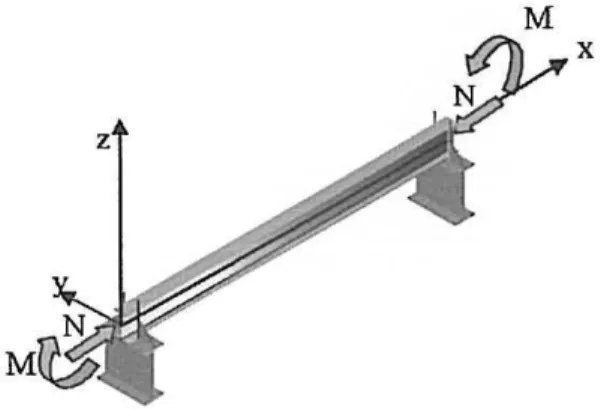
2.2 Case study
A simply supported beam with fork supports was chosen to explore the validity of the beam-column safety verifications, loaded with uniform moment in the major axis
and axial compression (Fig. I). An IPE 220 of steel grade S 235 was used, with a uniform temperature distribution in the cross section.
A lateral geometric imperfection given by the following expression was considered:
( I .
(m:)
YX)=SInFinally, the residual stresses adopted are constant across the thickness of the web and
of the flanges. Triangular distribution as in figure 2, with a maximum value of 0.3 x 235
MPa, for the S235 steel has been used [13].
3. THE EUROCODE MODELS FOR BENDING AND AXIAL FORCE UNDER FIRE
LOADING
3.1 Introduction
At this point the versions of Part 1.2 of Eurocode 3 from 1995 and 2002 for
combined bending and axial force under fire loading will be described .
3.2 Simple model according to Eurocode 3 (1995)
According to part 1-2 of the Eurocode 3 [14], elements with cross-sectional classes 1
and 2 submitted to bending and axial compression, in case of fire, must satisfY the
following condition:
where
and
N fl.Ed + K vM '·.fl .Ed ,,; 1
X min.fl AA
~
W k~
Cv 0 pI,)' J',8
1.2 .' YAI .fl Y"' .fl
Ky =1 ll yN fl.Ed
X y.fl Ak
f
1.2 y.a y
(3 )
-
[W -W ]
/I =
A ,
(2
f.I _4)
pl, y d ,yr,· . J.O PU .v .. W
cl ,y
but f.1 ,,; 0.9 (5)
where
X m;".fi is the minimum reduction factor of the axis yy and
zz;
Wp /,." is the plastic modulus in axis yy;
k,.,1} is the reduction factor of the yield strength at temperature
e
Y AI.fi is the partial safety coefficient in case of fire (usually YM .fi
=
1 );PM ,,, is the equivalent uniform moment factor, in this case (PAl v =1.1);
The reduction factor is calculated with the expressions from the part 1.1 ofEurocode
3 [9]. The reduction factor in case of fire, X y.fi and X =.fi' are determined like at room
temperature using the slenderness
1" .0
e,I"o
given by equation (6). The constant 1.2 isan empirical correction factor. In the calculation of the reduction factor in case of fire
the bucking curve used is the curve c (a.=0.49).
- -jE
y,O
Ay,O = A)'
k
£,0
- -jEo
A =,0
=
A = --"'--k£,0
where:
/I.)' e A = are the slenderness ofthe axis yy and
zz
at room temperature;k II 0 is the reduction factor of the elastic modulus at temperature
e .
The following values are also defined :
I ,.
N
fi,O,l/d =Ak,.,o
- -
'
-Y"' ,fi
My,jl,O,Rd .
=w
pl,y k .1',0£
Y"',fi
(6)
In order to compare results, the maximum value of the design moment is divided by
the plastic moment resistance at temperature
e.
Solving equation (3) for M .... fl .Ed anddividing by M v.fl .•. Rd from equation (7), yields
M .... fl,Ed
--"-"='--< --,-- --- ~
M ... ,fl,. ,Rd
I _ _
-...:... fJ ..!:.,,_ N .£fl~ , E::.a
_ _N fl,Ed
1 = '
-Xmin.fl N
1.2 fl,O.Rd
(8)
In addition, also from part 1.2 of Ee3 [14], a second condition related to
lateral-torsional buckling is also required, and the following formula must also be verified:
N fl,Ed
+
K LT Ad " .fl,Ed X=.fl Ak f " X LT W k f yI 2 .1',0 I 2 pl.y .1'.0
. rM ,fl ' rAf •fl
~ I (9)
with
Il LT
N
fl,EdK LT =1- but K LT ~ 1.0
X =.fl Ak
f
1.2 )",0 y
(10)
and
fJ LT =0.15A. =,o!3"I.Lt -0.15 but f.1 ~0 . 9 ( II)
where
PM.LT IS the equivalent uniform moment factor corresponding to lateral-torsional
buckling, in this case (PM.LT = PM.J' =1.1);
The reduction factor for lateral-torsional buckling is calculated according to the
The reduction factor in case of fire, X LT.fl' is detennine like at room temperature using
the slenderness
ILT
0 given by:( 12)
Again, in order to compare the results, the maximum value of the design moment is
divided by the plastic moment resistance at temperature
e.
Solving for M y .fl.Ed fromequation (9) and dividing by M y .Ji.O.Rd from equation (7), gives
M y, fi ,Ed < _ ---,-__ --'X=LT'--_ _ _ -;:-Il ___ N---"fic:::.E:::.d _ _
M y,fi.o.Rd X :.fi N
fl LT N fi,Ed 1.2 fi.O.Rd
1.2 1- - -
--'-'---( 13)
X :.fi N
1.2 fi.O,RdYM.fi
3.3 Simple model according to the new version ofEurocode 3 (2002)
According to the new version of Eurocode 3 [14] the elements with cross-sectional
classes sections I and 2 subjected to bending and axial compression, in case of fire,
must satisfY the condition:
N fl,Ed + K/v! y,fl,Ed < I
Ak
~
Wk
~
X min,ji y ,a pl ,y y,fJ
YM ,fl Y M,fl
where
K y =1 II" N fl.Ed
{, f ,.
X Y,flA (Y.O '
-Y At .};
but K < 3 y
-(14)
and
fly
=
(l.2f3A1 .y - 3)X;,.t, + 0.44f3A1 . .I' - 0.29 but II ~ 0.8 (16)with
1
(17)
X ji
=
rPo
+ ~[rP o y
-
[~o
r
where
rPo
=~
[I
+
aA o
+
(Jo
Y
]
(18)and
a
=
0 . 6S~23
7Jy
(1 9)X.1i is the reduction factor to the axis)0' and
zz
in case of fire;-
-~
o
A.
=
A-Y,-y.O Y k
E ,O
-
-~
O
A = A -
Y'-,,0 ' k E,O
(20)
with
Ay e A, are the slenderness of the axisyy and zz at room temperature;
k E.O is the reduction factor of the elastic modulus at temperature
e
Following the same strategy as before, solving for M y,ji.Ed from equation (14) and
dividing by M )"ji,O.Rd from equation (7), yields the ratio of applied moment versus
resisting moment for a given level of axial force :
lvII"ji,Ed < 1
(1 _
N ji,Ed ) (21 ) My, ji,O,Rd(1 _
J.l )' N ji'Ed ) Xmin. ji N ji.O,RdX y,ji N ji. O,Rd
where
and
where
_ _ N-,-fl=.E-=..d ---,,-_ + K LTM y.fl.Ed :> I
Ak
r,·
W k~
X: .ji )'.0 - - X LT,ji pl.)' y.O
Y!of ,fi Y r.l.fi
K - 1- JlLTN fl.Ed
LT -
j"
Xo.flAk Y.l1 '
-YM ,ji
but KLT :>1.0
P LT =O.IS}..o''' PM,Lt -0.15 but p :> 0.9
(22)
(23)
(24)
P
M .LT is the equivalent unifonn moment factor correspondinoo to lateral-torsionalbuckling, in this case (PM ,LT = PAl.,. = 1.1);
where
X LT,fl =
~
f
j
¢LT,O + [¢LT,(}
J'
-lA LT,O(2S)
with
(26)
a
=06SP3Jjy
(27)and
- - JE
'O
A =A
2:-LT." I.T k
E. (}
(28)
Similarly, for comparison, the maximum value of the design moment (taken from
equation (22» is divided by the plastic moment resistance at temperature (equation (7»,
M y .fl•Ed < XLr
(I
N fl.EdJ
M fl .II.Rd
(1-
J.lLrN fl.EdJ
X' .flN fl .II.RdX , .flN fl.O.Rd
(29)
4. COMPARATIVE ANALYSIS OF THE NUMERICAL RESULTS AND THE TWO
VERSIONS OF EUROCODE 3
4.1 Basic results: steel members loaded in compression or in bending
To establish the grounds for the subsequent analysis of the behaviour of
beam-columns, it is worth recalling the results of axially-compressed columns and
simply-supported beams loaded in pure bending under fire conditions.
For both versions of part 1.2 ofEurocode 3, figure 3 compares the axial resistance of
an axially-compressed pin-ended column, non-dimensionalised with respect to its
plastic resistance, for a range of non-dimensional slenderness,
X
LT.O ' with thecorresponding numerical results for various constant temperature simulations (400° to
700°C). It is noted that, although the numerical results apparently highlight a slight
unconservative nature of the eurocode design expressions, experimental results indicate
otherwise, an issue briefly discussed in the conclusions.
Analogously, figure 4 compares the non-dimensional bending resistance of a simply
supported beam under equal end moments from the two eurocodes proposals, against
the numerical results obtained using the program SAPIR for a range of uniform
temperatures from 400° to 700°C, for various levels of non-dimensional slenderness,
X
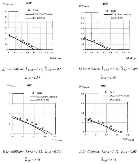
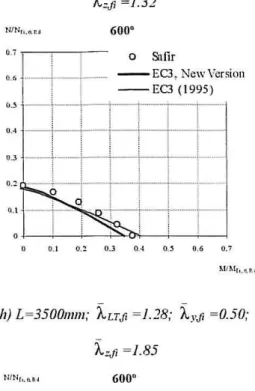
Lr II' In this case, the more recent eurocode design proposal provides perfect fit to the4.2 Beam-Column results: combined major-axis bending and axial force
In order to assess the eurocode design rules for bending and axial force, a parametric
study was carried out where the following parameters were considered :
(i) length ofbeam-column, L;
(ii) level of axial force, N / N fl.O.Rd ;
(iii) temperature.
For each length L, and for a chosen temperature, the eurocode design expressions
(13) and (29) were plotted for increasing ratios of N / N fl. O.Rd , together with the results
of the numerical simulations for that beam-column length. These results are illustrated
in the charts of Figures 5 and 6, for uniform temperatures of 400° and 600°C.
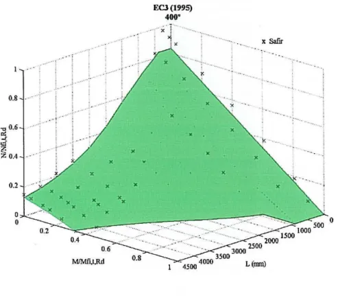
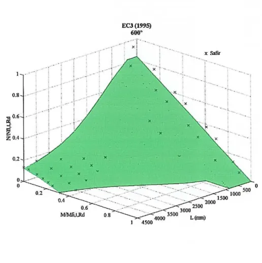
Overall, it can be seen that the eurocode results are mostly on the safe side, as can be
summarized in the 3D interaction surfaces of Figures 7 to 10. In each figure, the
continuous surface corresponds to the simple model of Eurocode whereas the cross
points result from the numerical simulations, only visible over the surface, i.e. when the
simple model is on the safe side. These figures clearly show that there are more points
in the safe side for the newer version.
5. CONCLUSIONS
The comparative analysis performed in this paper has shown that for the
beam-column IPE 220 studied with length varying between 0.5 and 4.5 m, the new version for
the fire part ofEurocode is safer than the version from 1995.
This new proposal is general on the safe side when compared to numerical results, as
especially for short members submitted mainly to axial forces. It has yet to be mentioned that Franssen et al [2] have calibrated the simple model against experimental
tests results in case of a 2D behaviour (no lateral torsional buckling) and have shown
that it is very much on the safe side to perform numerical analyses that consider
simultaneously a characteristic value for both imperfections, namely the geometrical out
of straightness and the residual strength. It can thus reasonable be expected that the simple model would prove to be on the safe side for the whole (M,N,L) range if
compared to experimental tests. Such tests involving 3D behaviour in elements
submitted to axial force and bending moment at elevated temperature have yet to be
performed.
8. REFERENCES
1. Franssen, J.-M. , Schleich, J.-B. and Cajot L.-G. , A Simple Model for Fire
Resistance of Axially-loaded Members According to Eurocode 3, Journal
0/
Constructional Steel Research, ELSEVlER, 1995, Vol. 35, pp . 49-69 .
2. Franssen, J.-M., Schleich, J.-B., Cajot, L.-G., Azpiazu, W., A Simple Model for the
Fire Resistance of Axially-loaded Members-Comparison with Experimental Results
Journal o/ Constructional Steel Research, ELSEVlER, 1996,Vol. 37, pp. 175-204.
3. Franssen, J. M., Taladona, D., Kruppa, J. , Cajot, L.G., Stability of Steel Columns in
Case of Fire: Experimental Evaluation, Journal
0/
Structural Engineering, 1998,Vol. 124, No. 2, pp. 158-163
4. CEN DRAFT prEN 1993-1-2, Eurocode 3 - Design of steel structures - part 1-2:
General Rules - Structural fire design, February, 2002.
5. Vila Real, P.M.M. and Franssen, J.-M. , Lateral buckling of steel I beams under fire
report No. 99/02 , Institute of Civil Engineering - Service Ponts et Charpents - of
the University of Liege, 1999.
6. Vila Real, P.M.M. and Franssen, J.-M., Numerical Modelling of Lateral Buckling
of Steel I Beams Under Fire Conditions - Comparison with Eurocode 3, Journal of
Fire Protection Engineering, USA, 2001, Vol. 11, No.2" pp. 112-128.
7. Vila Real, P.M.M. , Piloto, P.A.G. and Franssen, l-M. , A New Proposal ofa Simple
Model for the Lateral-Torsional Buckling of Unrestrained Steel I-Beams in Case of
Fire: Experimental and Numerical Validation, Journal of Constructional Steel
Research, ELSEVIER, 2003 , Vol. 5912, pp. 179-199.
8. Nwosu, D.L, Kodur, V.K.R. , Franssen, J.-M. , and Hum, J.K. , User Manual for
SAFIR. A Computer Program for Analysis of Structures at Elevated Temperature
Conditions, National Research Council Canada, int. Report 782, pp. 69, 1999.
9. EUROCODE 3, Design of Steel Structures - part 1-1. General rules and rules for
buildings. Draft ENV 1993-1-1, Commission of the European Communities,
Brussels, Belgium, 1992.
10. Franssen, J.-M. - "Modelling of the residual stresses influence in the behaviour of
hot-rolled profiles under fire conditions" (in French), Construction Metallique,
1989, Vol. 3, pp. 35-42.
11. Franssen, J. M. - "The unloading of building materials submitted to fire" , Fire
SajetyJournal, 1990, Vol. 16, pp. 213-227.
12. Souza, V., Franssen, J.-M. - Lateral Buckling of Steel I Beams at Elevated
Temperature - Comparison between the Modelling with Beam and Shell Elements,
Proc. 3rd European Conf. On Steel Structures, ISBN: 972-98376-3-5 , Coimbra,
Univ. de Coimbra, A. Lamas & L. Simoes da Silva ed. , pp. 1479-1488, 2002.
13. ECCS EUROPEAN CONVENTION FOR CONSTRUCTIONAL
Group 8.2 - System, "Ultimate Limit State Calculation of Sway Frames With Rigid
Joints", first edition, 1984.
14. CEN ENV 1993-1-2, Eurocode 3 - Design of steel structures - part 1-2: General
M
x
~_ , ~ 0.3
~
I{ ~
N/Nli.8,Rd
1.2 , - - -,---,----,,--.,---,-_.,-_--,,
;
!
;
·~~---f---+---
i;~~-!
I
I
10.8 ./=- =-=-=t ;- ~4 ---+--r--l
i
: ' ; - - - - 1 I I
I
!. _ _ _ '. _
-,- -,
1---+---; I
J
!--t---o
-- EC3(t9 9 ~)
1.0
_ _ EC3.Now\'o u ion
[] Sal-'r · ~O (lO
<> s.nr·~U O'
!J. s.nr·60 D"
o S . fir- ' CO'
0.6
j--+--0.4 .
---I -
+--1
0.2 -+---+--+
0.0 +---+---+---+--+---+--;_-i---+--+---1
0.0 0.2 0.4 0.6 0.8 1.0 1.2 1.4 1.6 2.0
A O.cam
Mt1\'lfi,O,Rd
1.2
'--,,-, --T,
- -'1---;'--""'1
' - "
-
~ C3. N .... ,V .... ;",__ L __ J __ .. _
.
.J_ .. __
L__
~ ~ ~~~ :~:
1,0 k<,.,..-i---+-- 1 I
!
1 I- -100 (1 993)
0.8 i ---!--\-_:II-_-i,I--t--r ~ '~'; I'~~':':~' -"
.·_-il''_ .. ·.-___
·_i '._ . ' , !1 I
I0,6
I"
,
I - .--'- ";--,T--'
._ .. "
!
I
I
!
i ! !I
0,4 -
--r--r-!1---1-
'._ t " j-! ! ' ,
I
! . !
~--0,2
0,0 -!----\----\----\--+--+--+---!---!---!---1
0,0 0,2 0, 4 0.6 0.8 1,0 1,2 1, 4 1,6 2,0
ALT ,O,cum
N I Nh. t. u
o SilEr
- -EC3 ,Ncw Vcr~ion
- - EC3 (1995)
0.6.--t-.
!
Io . ~ t · t
-. I
•. , _ ._ . _i._~i
_ _
iI
o.
"•..
"a) L =250mm; A.LTJi =0.12; A.yJi =0.03;
400~
o SaEr
- - EC3,NcwVef!lio n
- - EC3 (1995)
,
..
0-'
o . ~ O.M I
!vI/ Mfi, B,P.d
-
-c) L =1000mlll; A.LTJi =0.45; A.yJi =0.14;
A.',1i =0.51
NINf; .~ . P'd
0.' o SUrD"
- - EC3, NewVcr.;ion
0 .1 O. l O. l 04 n.J Oft 0 . 7
M /Mr..u .d
-
-e) L =]OOOlllm; A.LTJi =0.82; A..I ~ i =0.28;
NINI< ... Ic ,
...
.,
o Sanr
- - EC3.NewVers io n
- - EC3 (1995)
I
•.• j--+--+'\
"j--+--" " ""
-
-b) L=500Illm; A.LTJi =0.23; A.yJi =0.07;
A.',1i =0.26
4000
o Sufir
_ _ EC3 .NcwVcrsion
- - EC3 (1995 )
0.' - - , - -'- -'--1'"
1
i
i
'I-r--I
I io.
-[-r--l-T--i . i
I
•.
,- ,-
..
--,--,-0.'
..
,•..
...
~I / l' ... lf; . ~ . r.d
d) L= 1500mm; A.LTJi =0.64; A.yJi =0.21;
A."" =0.77
o surlf
- -EC3,NcwVer.; ion
- - EC3 (1995)
"
0. 1 o_~ O.l 04 C.! 0 ~ 0 .7
M f! l.'lf;, ~ .Il d
NfNn.o.M
0. 1 o Su fii'
- - Ee3. No!w Vo!r.>io n
0 .6
'--1-0. '
t--+-i--t---i,
~-- ~-- Eel (1995 )
... -l
0.' -'-r! -
1--,-:-,
-+1-+-
1'0 '
I I ,
i
O ' ~ --j-"
i
I
!i
0.'
"-i-:-
i--~
-1-1-'
<l . 1 11 .2 0.3 flA \l . ~ (1.6 0.1
M!!Vl fi.o.IU
g) L~ 30001ll1ll; iLTJi ~ /.I];
i,.Ji
~ 0"+2 ;NIN, .... ..
•. ,r----,
I
o SuflT
- - EC3.NewVcrsion
- - EC3 (1995)
"
·~--I--I
! '·--IU
I---i---0.'
t---+- ~o
10
I
I:r-,
:• 1 -. --i----i--~~>__l
0.'
-
-i) L ~ 40001ll1ll; ALTJi ~ 1.35; AyJi ~ 0 .56;
N/ NIi.o.ll •
o SufiI'
0.' , - - - ; - -
!
- - EC 3, No!w Vcr.;io n
... --r
- - EC3{1995) Ml-ti-+-t--+
I-" 1-1-,
-+-1
-+'-+1
-i'-i-" - 1-'-11
.-,-0.' _ ; - _ _ _ _ _
-1_--1_
,O !
I , , I
0'
- '-1
o ~ -r---I--,--""0. 1 0.2 0 .1 0.4 o . ~ 0.6 0.7
rvWV!n.e,u
11) L~ 35001ll1ll ; iLTJi ~ / .] ./ ;
i ..
Ji ~ 0 . ./9;io,ji
~ / .8 0NlNn.e.Ri
o Sufll"
0" , - - -,
I
_ _ EC3.NewVers lon
- - EC3 (\995 )
O.J - - - - J _ _ _ l----~_._ ..
,
!
i
i
jo . ~
---r---t---r--·
o
I
I
!- o - ~
-I-!
!
I
O ~--+--+-~~~~~
"
0 .2 0 .·'j) L ~ 45001ll1ll; iLTJi ~ / . ./6; i y•fi ~ 0. 63;
; !
; ; o Safir
o
"'
I
I
--EC3 , New Ver!:.;on
... 0 _ _ _ _
- - EC3( 1995)
d
1 101 .6 ' I· ----i "'O' ~ -I-· O
-r_--t---"A j ---+---. ~. .. _+.0· __
1_· __
0.1
---f--..
L
o
0.2 " A "., 0.8
a) L ~ 25017l17l; "'LTJi ~ 0.1 2; "'y,1i ~ O . 04;
NI Nr, ... , ....
'r-+l
\
i 0 Sa fir" ' _ _ 1 ____ - - ' - -EC3, New Version
.
I
i
--EC3 ( 1995 )" __
I_LJ~_"' _ O
_i_
J
___
I ___
~
,
1
__ -'-_
. 1
0. 2
!
, .,---+----'---i---'<;4----I
0.1 'A
,.,
" MIM, •. I. ' .<
c) L ~ 1 000171111; iLTJi ~0.46 ; i YJi ~ 0 . 14 ;
N!Nr, .... ~.
0. ' , , ,
-,, ---1
o S.'lfir- - - EC3 , New Versio n --EC3 (1995 )
"
-+--+---i--'
Ir-t
'--'--
i+-1-i--i-ii
; I i i i 1
0.' . _,- ,--:- - - 1 -1
-I:
I,
i0.1 - ---I - j : I
-I
1 , , '0. 1 : , i . I ,
--I!- ·- - ~ ·--!
-"
..
0 .1 0.2 0. 3 o 4 o . ~ tI . ~ tI . 7 MI "lh . I. U
e)-L~2000Il1m; "'LTJi ~ 0.85; "'y,1i =0.29;
i
0 &tfiri 1 - - -EC3, New Version
,.,
-- - : - - i - - - E C3 (1995 ): i l l
I
. O ! I
0./, - - - ; - oj j j "
-'A t- - - i - --i
0.2 0"; 0.' 0.'
b) L ~ 5001711l1; "'LTJi =0.24; "'YJi =0.07;
"';Ji
=0.26600"
1 . 0 Sufir
~
I ---
EC3 , New Version0.' . ___ ._. _ _ l - - - - EC3 ( 1995)
; j I
. , , I
i i '
,., t--+-+-1-1-i
"A _ _ _
I_····-··-·-r··_··-·!-··--·-r
0.2
0 .2 OA 0 .6
,.,
""Mr. ... l.
d) L~15001l1111; "'LTJi ~ 0.66 ; "'yJi =0. 22;
Nlt/r,.".,
" , -
-,--,--I
!0 . 6 - 1 - _ ' _
!
o Snfir
- - - EC3 , New Version
--EC3 (1995 )
o . ~
----1--:-
I ; ; :I
0..1
-1--I--I--I--·l--·J--I -1--I--I--I--·l--·J--I -1--I--I--I--·l--·J--I -1--I--I--I--·l--·J--I
!
I
._!! _ ..
-!=]~:=[=J=~
, ! i 1
0.'
o . ~
r ! 1
,.,
j--'--:--+--,"'''';;D'i',---l---'--~ 1 I
I
0. 1 0.2 0. 3 0 .4 o.~ 0 .6 0 .7
'i..'Ji ~ /.06
lUNr. . •• • tl / N" ...
..,
, -,-- "
-i
I
0 ,6 ···_-_·t,.-·_-'Hr'-- --EC3 , New Version
I --EC3 (1995 )
,.S
--'I--l--j'
t-!
!I
I IOA - - r
-'r-r----.--'--.--! 1 I ! [ j
, .s
"-'-r-'I---i
i
i
t----" -- ; --
!
l
i
I
".,
--'-_
.. :-..! !
o Safir
:: j ;
i _0_
~~ ,
New VersiollI
--EC3 (1995) " - 1 - : - - ' - '. • ! I iI
r---:
, .• 1---1-"Si."",·!-H!I~
i i
0 . 1 0. 2 0.3 0.4 o . ~ 0 .6 0.7 0. ] I.l.:! 0 .3 OA a.~ U.6 0. 7
g) L ~ 30001ll1ll; 'i..LTJi ~ /.15 ; 'i.. yJi ~ 0.43; /7) L ~ 35001ll1ll; ALTJi ~ /.]8; A}.Ji ~ O.50;
0..1 , ,
-o Safir ,-' ' - - -'1 - - 0 Snfir
".S
, -_ _
.+1,,__
--EC3 , NewVersioll,_ . --EC3 (1995)
I
I
,., 1 _ _
;1-__
! __
j __
I
I ,i
I
!
! i
- - E O , New Version
--EC3 (1995)
,.S
i
,., - - - - , ----+----1---1
T
I
,
..
"
..
o . ~ ,.SM/ )l.l{" .. u
~IIM" ... ...
j) L ~4 5001ll1ll; 'i..LTJi ~J.50 ; 'i.."Ji ~ O . 65;
0.8
-00.6
'"
Jci
1';
;Z 0.4
0.2 o o .... . ; . ... . , .. , ···]··· 1· . ~ ... . ,
.!. ... '
... : ... . .;.. ' . .'V
:"".; :
~ .. , ...
1 .
.
x
• x
M/Mft,I,RrI
. . .:, ... .
x
EC3(1995) 400"
x ;
~ ... j )( ... x
•
• • ..." '; .
•
•
•
x
x Safu ....
" ' : .
... ... ...
. .. ... .
' . ~ ...
"; ~ ; . . . .. . .
. . ~ '" ~ . ... ,
. .. ~ ...
. . ~
x . .. " . ' .. ~
.... .
.... ,. ' .. "" . ... ' 3500
3000
2500 2000 1500 1000 500
4500 4000 L (rom)
o
0.'
;il 0.6
J
'"
;;;
Z 0.4
0.2
o o
•• j • • •• .... : .. . , -~ ... : .. , .. .. ~ ... , .. x x
•
x•
• •
Eel NewVersiOil
400'
.,~ " 'x' .
'I( • • •••
• x Safu
. . ~. x
•
~ •..
•
x x
•
•
•""
•
•. ...
. . .. ~ .
' x
".
' x' : '
. .... : ... . . " .
...
. ...
x " .
". 'I.
• lit " •
~~
' M ' ~
: '~ ': ":" S:""' " ~
·· :::: ···· :.'
...
~
~
O
.. :." . . . ; .... ,'. . ".:: ' 1500 1000 500
• •
2500 2000 3500 3000
4500 4000 L (om)
0.6 ...
MlMfi,t,Rd 0.'
0.8 0.2 o o ... . . . .. ... . ...
l.·o' -t" ..
; • ••• • j • ••
.... ..
:
.. . ... . ... ... .
,
..
..
y
j ., : .
~ ,l
. ~. .. . )( x 0.' MIMfi.t.Rd x x ... ... . ~ ; .: 0.8 ED (1995) 600" .. ; ' . ... .. ....
' .. . -. x Saf~
x
" ... . ~ ..
. ... .
x ' , 0., ...
x x ...
. .... ... : .... .
x
x
. ....
' X " "
x x ... . :
' :" K
x
,' , " ::: . '" ... .. . : ... . :.,..,.:. .. . .. , ..
2500 1000 1500 1000 500
3000
~- -----4000 3500 L (nun)
4500
o
0 .•
"a 0.6
"
J"
;;;Z 0.4
. ~ .. ' ... "
. i. ··
.: . . '
. .. . . "'
:" .'
4·"
.. [ . . ' ....
.' ~ .... . '
ECl New Version 600"
x
'X
x
x x
•
" . x 5aflr
' j ••.
.... .. ~ .
' '' ..
x
~ L-:"C;-:;;::-:::""-
·::" ::-" ~
..
;~" .~· .~·::::
...
: ·:::"· "'·" " ·"':: ·:: ·~·
-.-: ... : ...
::
...
::
..
7 "",7'~
::;1::OOO :;:' :'00:-O
.. :... 2000 1500
.. ;:" , 3000 2500
3500
4500 4000 1.. (mm)