The Brazilian standard ABNT NBR 15200 is in revision. Some omissions on the design of beams in the 2004 version of the standard will be in-cluded now. Possibility of reduction of c1 in situations of safety reserves, different design for unidirectional ribbed slab and lateral increase in c1 in some cases are the cases of interest in this work. The Eurocode provides recommendations on these items, however, they are not considered adequate to Brazilian design. The objective of this article is to perform thermal or structural analyzes of reinforced concrete beams and propose alternatives to the recommendations of Eurocode in order to standardize them at this stage of revision of the Brazilian standard.
Keywords: ire, design, beam, ire safety.
A norma brasileira ABNT NBR 15200 está em fase de revisão. Algumas omissões sobre o dimensionamento de vigas, na versão de 2004 da norma, serão incluídas agora. Possibilidade de redução do c1 em casos em que haja reserva de segurança, dimensionamento distinto para laje nervurada unidirecional e aumento de c1 lateral em algumas situações são os casos de interesse neste trabalho. O Eurocode fornece recomendações a respeito desses itens, no entanto, não são consideradas adequadas aos costumes brasileiros de projeto. O objetivo deste trabalho é, por meio de análise térmica ou estrutural de vigas de concreto armado, propor alternativas às recomendações do Eurocode, visando normatizá-las, já nesta fase de revisão da norma brasileira.
Palavras-chave: incêndio, dimensionamento, vigas, segurança contra incêndio.
Concrete beams ire design. Enhancement of some
recommendations of the Eurocode
Dimensionamento de vigas de concreto armado em
situação de incêndio. Aprimoramento de algumas
recomendações do Eurocode
V. P. SilVa a
a Professor Doutor, Departamento de Engenharia de Estruturas e Geotécnica, Escola Politécnica, Universidade de São Paulo, [email protected] ,
Av. Prof. Almeida Prado, trav. 2, 271 Cid. Universitária, São Paulo, SP, Brasil
Received: 13 Dec 2010 • Accepted: 24 Mar 2011 • Available Online: 10 Jun 2011
abstract
278 IBRACON Structures and Materials Journal • 2011 • vol. 4 • nº 2
1. introduction
The Brazilian standard ABNT NBR 15200:2004 [1] is under revi-sion and the European standard Eurocode [2] is the main refe-rence standard. Since some omissions from the 2004 version of ABNT NBR 15200 will now be included, the aim is to improve the Eurocode recommendations related to such additions, suggesting more expeditious procedures for the Brazilian standard.
The Eurocode [2] allows the design of reinforced concrete beams in ire situation using the tabular method (tables 1 and 2), which is associated with the time required for ire resistance (TRRF), the smallest dimension of the beam (bmin) and the distance between the centroid of the reinforced steel and the face exposed to ire (c1). The tables of the simpliied method are constructed assuming the following hypotheses:
n Beams under slabs
n Heating on the sides and bottom of the beam (igure 1) n Maximum temperature in the reinforced steel at the sofit of the
beam equal to 500 °C (θcr)
n Redistribution of bending moments in the case of continuous beams
ABNT NBR 15200:2004 [1] presents the same tables as the Euro-code [2] up to TRRF = 120 min, and the review will include infor-mation concerning TRRF = 180 min. Three recommendations in [2] should be aggregated to the revision of ABNT NBR 15200:2004 [1]. They are detailed in sections 1.1 to 1.3.
1.1 Reduction of the values of c
1The values of c1 in the tables were determined assuming
= 0.7 and = 1 where Sd,i e Sd are the design values of the
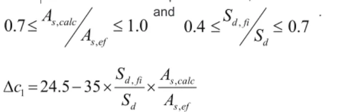
effect of actions in ire situation and at room temperature, respec-tively, and As,calc and As,ef at room temperature, respectively, and As,calc and As,ef are the values of the areas of the reinforcement required for ultimate limit state at room temperature and the rein-forcement provided, respectively. If these values are lower, c1 can be reduced by ∆c1, as in Equation 1, where θcr in °C is given by Equation 2, where, fyk and σs,i are the yield strength of steel at room temperature and steel stress in ire, respectively.
2, the distance c1ℓ (Figure 2) at the bottom of the beams should be 10 mm larger than the c1 given by those tables.
2. analysis
The Eurocode is an internationally recognized standard and the most up-to-date with regard to structures in ire, thus unsuspicious in its recommendations. However, the three recommendations mentioned in paragraph 1 herein can be adapted to be better un-derstood and used by practicing engineers. This being our purpo-se, the results with the demonstrations are presented in the follo-wing items.
2.1 Reduction of c
1The reduction factor ks (q) recommended for simpliied or advan -ced analytical methods is presented in [1]. However, for the tabular method, an old factor ks (q) was used according to Equations 4. Graphically, both factors can be seen in Figure 3.
Given the dificulty that this procedure could cause to the user of the standard, a simpler alternative was sought without changing the security level required. The procedure is detailed below. The reduction factor ks(q) is determined by means of Equations 4.
1.2 Minimum dimensions for one-way reinforced
ribbed slab
In the case of ribbed slabs simply supported, the tabular method leads to Table 3 where “h” is the minimum thickness of the slab when compartmentalization is required.
Table 3, however, applies only to slabs reinforced in two directions. For one-way ribbed slabs, table 1 is applied to the ribs and table 4 to the lange.
Thus, for one-layer reinforced steel ribs, table 1 becomes table 5, where c1ℓ is deined in section 1.3.
1.3 Increase of the lateral c
1in some situations
280 IBRACON Structures and Materials Journal • 2011 • vol. 4 • nº 2 From Equation 3, it is possible to determine ks (θcr) in function of
and (Equation 5) with γs = 1.15, as recommended
by ABNT NBR 6118:2003.
Within of the ranges and
7
.
0
4
.
0
≤
,≤
d fi d
S
S
, the values of ks are presented in table 6.
No values
d fi d
S
S
,allows adopting = 0.7, as an alternative to the exact calculation.
θcr is determined by Equation 6, the polynomial regression of Equa-tions 4 for the range 400 to 800°C. A good approximation can be found in igure 4.
Thus, at the same previous intervals, it is possible to build table 7. Finally, D c1 is determined by Equation 1. This procedure results in Table 8. Equation 7 very well represents Table 8 in the intervals
and .
The difference between ∆c1 given by Equation 7 and by Table 8 can be seen in Table 9. Values are in mm and negatives mean unsafety. In practice, the differences were insigniicant.
2.2 Minimum dimensions for one-way ribbed slab
Since the irst column of Table 2 is used, the widths become stan-dards for manufacturers of plastic formwork for ribbed slabs. Ho-wever, the widths of the irst column of Table 3 are not the same given in column 1 of Table 2. This reason justiies this work. Based on the simpliied method recommended by the Eurocode, sear-ched values of c1 that match the widths of 8 cm, 10 cm, 12 cm, 16 cm and 22 cm and the temperature in the reinforcement concrete? does not exceed 500oC in the TRRF.
2.2.1 Geometry and discretization of the models
For simplicity, rectangular ribs were adopted. For safety reasons, the rib height is admitted to be equal to 1.5 times the width and it is overlaid with a 5 cm thick and 60 cm wide slab. The widths adopted were 8 cm, 10 cm, 12 cm, 16 cm and 22 cm. The Swedish software Super Tempcalc was employed for thermal analysis [3].
An example of the geometry provided for the software can be seen in Figure 5. In it, the symbol “1” next to the edge of the concrete elements means the heated faces, i.e., the heat lux was provided through the lower boundary of the model. The upper face of the slab was, on the side of safety, admitted to be adiabatic, i.e., there is no heat exchange with the environment.
282 IBRACON Structures and Materials Journal • 2011 • vol. 4 • nº 2 the middle of the rib (Figure 7a, at relatively low temperatures)
and CG level in rib were determined, near the face (Figure 7b, high temperatures). The conclusion is that for the thermal analy-sis in the lower region of the ribs, both discretizations lead to similar responses. Next, the simplest mesh was used.
2.2.2 Parameters used
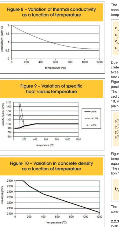
nor-mal density is expressed by equation 8, where λc is the thermal conductivity of concrete in W/m ºC and q is the temperature in °C.
(8)
λ
=2
-0.2451
(
100
θ
+
(
0.0107
(
100
θ
2(
Equation 8 is valid for temperatures between 20ºC and 1200°C and is plotted in Figure 8.
The variation of speciic heat as a function of temperature, cp,q, concrete to dry silica is represented by equation 9, where q is the temperature in °C.
Due to the evaporation of free water present in the hardened con-crete, the value of speciic heat is constant for temperatures be -tween 100°C and 115ºC. The value of cp, peak depends on the mois-ture content of concrete, as shown in Table 10.
Figure 9 shows the variation of speciic heat as a function of tem-perature. In this study, moisture equal to 1.5% was adopted. The variation in concrete density with temperature, ρq, is inluen-ced by loss of water and can be determined according to equations 10, where q is the temperature in °C and r(20 oC) is the density of plain concrete at room temperature (20 ºC).
Figure 10 illustrates the variation in concrete density as a function of temperature, considering the concrete density at room temperature equal to 2400 kg/m³, as recommended by the ABNT NBR 6118:2003. The mathematical ire model used was the ISO-ire [4] as in Equa -tion 11 and illustrated in Figure 11.
The emissivity factor was 0.7 and the heat transfer coeficient by convection in the face exposed to ire was 25 W/m2 °C.
2.2.3 Thermal analysis results
284 IBRACON Structures and Materials Journal • 2011 • vol. 4 • nº 2 determined as exempliied in Figures 12 and 13.
From the temperatures ields and based on the simpliied method proposed by the Eurocode [2], the minimum values for c1 and width of the ribs for several TRRF’s were determined. These values are presented below.
According to Figure 14, for the rib width equal to 8 cm, c1 must be 25 mm for TRRF equal to 30 min, with no need to impose c1ℓ.
According to Figure 15, for the rib width of 10 cm, c1 must be 20 mm for TRRF equal to 30 min, then an alternative to the constant value of Table 5.
In igure 16, for the rib width of 10 cm, c1 is 45 mm. Noting that one-way slabs can use just a rib for reinforcement, these dimensions will be consi-dered. For the case of using up to two bars, an alternative was studied for the 12-cm width. According to Figure 17 for the rib width equal to 12 cm, c1 must be 40 mm for TRRF equal to 60 min, with no need to impose c1ℓ.
Figure 18 proves that there is not c1 that its the 12-cm width for TRRF equal to 90 min. In igure 19, for the rib width equal to 16 cm, c1 must be 50 mm for TRRF equal to 90 minutes, an alternative to table 5.
In spite of the differing widths standard, cases of width 13 cm, 14 cm and 15 cm were studied, and the results can be seen in igures 20 to 22. Respectively, the values of c1 are 60 mm, 55 mm and 50 mm.
According to Figures 23 and 24, for rib widths equal to 16 cm and 22 cm, c1 must be 65 mm and 50 mm, respectively, for TRRF equal to 120 min, an alternative to table 5.
According to Figure 25, for the rib width equal to 22 cm, c1 must be 80 mm for TRRF equal to 180 min, an alternative to table 5. In short, the results are presented in table 11.
2.3 Increasing the lateral c
1in some cases
Given the dificulty of specifying two different covers for the same beam, an alternative is presented here to the recommendation of the EC (2004), employing the procedure presented below. Just as in 2.2, with the aid of the Super Tempcalc software, models were built for widths: 8 cm, 12 cm, 14 cm, 16 cm, 19 cm, 24 cm, 25 cm, 30 cm and 40 cm. Temperature ields were determined for each of these models. In igure 26, an example for the 19 cm width. From tables 1 and 2, columns 1 and 2 for each TRRF (30 to 180 min), the following temperatures and, respectively, ks were determined:
n θ1 in a place distant c1 from the lower horizontal face of the beam and (c1 + 10) mm from the lateral face
n θ2 in a place distant c1 from both the lower horizontal face of the beam and the lateral face
min for simple supported beam and continuous beam. In cases of Figure 26, we have:
n simple supported beam, θ2 = 508.32 °C, ks (θ2) = 0.76 and θ1 =
484 °C, ks (θ1) = 0.815
n continuous beam, θ2 = 675.86 °C, ks (θ2) = 0.288 and θ1 =
634.32°C, ks (θ1) = 0.388
Then, relationship ks (θ2)/ks (θ1) was determined. For example, in cases of igure 26, ks (θ2)/ks (θ1) = 0.9 for the case of simple sup
-ported beam and 0.74 for the continuous beam.
sec-286 IBRACON Structures and Materials Journal • 2011 • vol. 4 • nº 2 tion of a reinforced bar with a certain diameter is always less than
70% of the diameter of a section immediately above, as in ABNT NBR 7480:2007 [5]. Therefore, if instead of c1 the diameter is incre-ased, safety will be strengthened.
3. Conclusions
A structural and thermal analysis was performed for proposing al-ternatives to the recommendations of Eurocode 2, part 1.2, whi-ch is the model for the ABNT NBR 15200:2004 review. After this analysis, the following proposals for the revision of the Brazilian standards are presented:
The values of c1 given in tables 1 and 2 herein may be reduced of the ∆c1 as shown in the equation below, valid in the ranges:
and .
Table 3 is only for two-way ribbed slabs. For unidirectional slabs, the table presented below should be applied to the ribs.
the width bmin indicated in column 2 of tables 1 and 2, the distance between the CG of the reinforcement in the corner and the face ex-posed to ire should be 10 mm larger than those c1 tabled. Alterna-tively, if this increase does not apply, the corner reinforcement has to be speciied with a diameter immediately above that designed, according to ABNT NBR 7480.
4. acknowledgements
The author thanks Astra S/A Indústria e Comércio, Atex do Bra -sil Ltda., Ulma Andaimes, Formas e Escoramentos, Ltda, , CNPq - the Brazilian National Council of Scientiic and Technological
Development, and FAPESP - the State of São Paulo Research Foundation.
5. References
[01] Brazilian Association of Technical Standards (ABNT). Concrete ire design. NBR 15200. Rio de Janeiro. 2004 (in Portuguese)
288 IBRACON Structures and Materials Journal • 2011 • vol. 4 • nº 2 [03] Fire Safety Design (FSD). TCD with SUPER-TEMP
CALC. Lund: Fire Safety Design Ltd., 2000. Disponível em http://www.fsd.se/eng/index.html
[acesso em 09.10.2002].
[04] International Organization for Standardization. ISO 834: ire-resistance tests: elements of building construction: part 1.1: general requirements for ire resistance testing. 25 p. Revision of irst edition (ISO 834:1975). Geneva.1990.