Multicarrier Waveform Candidates for Beyond 5G
Bahram Khan and Fernando J. VelezInstituto de Telecomunicações and DEM-Universidade da Beira Interior 6201–001 Covilhã, Portugal
Email: [email protected], [email protected] Abstract— To fulfil the requirements of 5G vision of
“everything everywhere and always connected”, a new waveform must contain the features to support a greater number of users on high data rate. Although Orthogonal Frequency Division Multiplexing (OFDM) has been widely used in the 4th generation, but it can hardly meet the needs of 5G vision. However, many waveforms have been proposed to cope with new challenges. In this paper, we have presented a comparative analysis of several waveform candidates (FBMC, GFDM, UFMC, F-OFDM) on the basis of complexity, hardware design and other valuable characteristics. Filter based waveforms have much better Out of Band Emission (OoBE) as compared to OFDM. However, F-OFDM has smaller filter length compared to filter-based waveforms and provides better transmission with multiple antenna system without any extra processing, while providing flexible frequency multiplexing, shorter latency and relaxed synchronization as compared to other waveforms.
Keywords—5G, UFMC, FBMC, F-OFDM, GFDM, Multicarrier Waveforms.
I. INTRODUCTION
The Mobile and wireless communication Enablers for the Twenty-twenty Information Society (METIS) 5G system concept is highly flexible and configurable in order to adapt to the large deviation in 5G desires (data rate, latency, number of devices connectivity, etc.) that follow in diverse scenarios. METIS 5G concept have three scenarios services: extreme mobile broadband (xMBB), massive Machine Type Communication (mMTC), ultra-reliable Machine Type Communication (uMTC) are shown in Fig.1. First one (xMBB) provides service like increased data rates, but also improved Quality of Experience (QoE) through reliable provisioning of moderate rates. It degrades the performance gracefully in terms of data rate and latency as the number of users increases. Whereas mMTC provides connectivity for a large number of devices. The key objective of this service is to connect enormous number of devices. Third one (uMTC) is time-critical package that addresses the applications such as vehicle-to-vehicle and industrial control. The main objective of this service is high reliability when the total of devices and the necessary data rates are fairly low compared to mMTC[1].
In the above-defined services there are several challenges that need to be well-thought-out while designing the 5G, as System would be complex, costly and inefficient by designing a distinct radio system for respectively above-mentioned service to meet heterogeneous desires. On the other side, it is difficult to design a composite radio frame structure that fulfil the desires for entire types of services. For example, mMTC may require large symbol duration to support massive delay tolerant devices. Furthermore, uMBB required reliability and latency, so symbol duration must be smaller. Hence, there is a trade-off between subcarrier spacing and symbol duration to accomplish the desires [2]. A new waveform must have
following qualities to realize the demands of 5G; low Out of band emission (OoBE), Relaxed Synchronization and Flexibility. Low OoBE reduces the guard band to a smaller value to acquire spectrum efficient transmission [3]. It also offers a basis for supporting many types of services with special frame structure existing in one baseband with almost ignorable interference [4].
In a second scenario, a huge total of users are estimated to be supported in 5G MTC, particularly for the Internet of things (IoT), which makes synchronization tough. Therefore, a new waveform must support asynchronous communications which lead to simplified transceiver processing [5]. Wireless communication systems do not have infinite resources and demand effective management [6]. Therefore, wireless communications should be flexible. For example, on the basis of SNR and application data requirements, users require a flexible architecture to support their needs. One of the possible solutions is to design the modulation parameters (e.g., symbol period and subcarrier width) independently, which is simply possible over flexible architecture. Several techniques (FDM, CDMA, TDM) have been proposed in former to make it possible which have their own pros and cons [7]. The leading objective of the paper is to present comparison and demonstrate a comprehensive overview of multicarrier waveforms with respective to baseband complexity, data rate, out of band emission (OoBE), relax synchronization, latency and system flexibility. This proposed analysis shows the interest in designing and implementing alternatives to classical Universal Filter Bank Multicarrier (UFMC).
The remaining of the paper is structured as follows. In section II, a brief introduction of candidate waveforms is being discussed, while in Section III the hardware complexity comparison of candidate waveforms is addressed, followed by a comprehensive summary of their characteristics comparison among the possible waveforms is given in detail. Finally, conclusions are drawn in Section IV.
Fig. 1. The three generic 5G services emphasize different 5G requirements, adapted from [1].
II. CANDIDATE WAVEFORMS
A brief introduction of 5G waveform candidates is given in this section.
A. FBMC
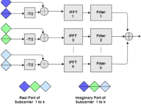
Figure 2 shows the structure of Filter Bank Multicarrier (FBMC), where K is the number of subcarriers and T is the time interval of FBMC symbol. Compared to Orthogonal Frequency Division Multiplexing (OFDM), it has three major differences from. First, it is using OQAM mapping instead of QAM mapping. Each symbol is splitted into real and imaginary parts, and a time delay (T/2) is applied on imaginary part. Then OQAM signals are combined and modulated by a specific subcarrier frequency and transmitted. Reverse process is applied on the receiver end. OQAM mapping reduces Inter Carrier Interference (ICI) when appropriate filtering is applied. Second it applied Poly Phase Network (PPN) filtering after IFFT process. This performs enhanced frequency and/or time localization depending on the shape and the length of the used prototype filter. This time and frequency localization reduce ISI and ICI respectively [8]. Third, no cyclic prefix is required because the best frequency and time localization through filtering and OQAM modulation process. Due to per subcarrier filtering and coordinative process of OQAM and filtering, better Out of Band Emission (OoBE) can be achieved, but Filter tail is much longer as compared to other filter-based waveforms which is not suitable for short packet transmission and low latency communication [9].
Fig. 2. System structure for FBMC, adapted from [9]. B. GFDM
Generalized Frequency Division Multiplexing (GFDM) is generalized with a new concept and is composed of non-orthogonal subcarrier which spread the data in time and frequency dimensional blocks as shown in Fig. 3. Total number of complex data symbols is equal to KM where K is number of subcarriers and M is the number of sub symbols.
Figure 4 shows the block diagram of the GFDM transceiver. Data coming from mapper is up sampled so that pulse-shaping circular filter g[n] can be applied through a convolution process [10]. This filtering process is applied subcarrier wise that improves Out of Band Emissions (OoBE) but generate Inter Symbol Interference (ISI), which can be removed by adding the Cyclic Prefix (CP). To enhance the spectral efficiency, the tail biting technique can be applied to reduce the CP length [11].
GFDM provides a low latency signal because of circular filtering with prototype filters, instead of linear convolution that is used in FBMC. It used one CP for one block slightly than a CP for every multicarrier symbol, which results in enhanced
spectral efficiency. Inter Carrier Interference (ICI) is not completely removed due to non-orthogonal neighbouring subcarriers.
Fig. 3. Time and frequency blocks in GFDM, adapted from [10].
Fig. 4. GFDM Modulation/Demodulation Function Block Diagram [11]. C. UFMC
UFMC is discussed in this part of the paper, which focusses the distinctions of upcoming modulations technique for 5G wireless communication technology. Fourth generation wireless communication system OFDM is an admirable choice, however 4G modulation technique experience high peak to average power ratio (PAPR) hitch, also it has high side band leakage. The current 4G system depend on OFDM waveform, which is not suitable for supporting the 5G and beyond applications, that 5G and beyond will offer. 5G technology is expected to have different requirements higher data rates, lower latency and efficient spectrum usage when relate to the existing wireless technology.
Currently researchers working on multiple schemes and being investigated new waveforms. UFMC scheme, that can overcome the limitations of OFDM, the generalization of OFDM and FBMC scheme is UFMC. Thorsten Wild and Frank Schaich in paper [12] proposed the first model of UFMC.
Fig. 5 shows the transmitter of this model, where 1024 points IDFT and filter Dolph-Chebyshev having length L=73 in each branch are considered. The data from mapper is divided into number of RB (12 subcarrier) and before taking IDFT zero is padded to each branch. In each branch, data is shifted by 12 carriers and accordingly the zeros are padded.
Data is filtered using Dolph-Chebyshev after taking IDFT. Dolph-Chebyshev is a type of filter that minimizes side lobes and main lobe width in the spectrum. On each branch filter is a shifted version of Dolph-Chebyshev, which perform convolution operation. The output from each filter is then added to get final output. Efficient spectrum management is a clear advantage of the UFMC proposed in [13]. However, it has still
high complexity than conventional OFDM, and further research is needed to investigate a scheme which can easily be implement on hardware.
Fig. 5. UFMC transmitter previous scheme [13].
In [13] a new approach is presented for UFMC (basis on hardware) which is better than Thorsten Wild and Frank Schaich approach [12]. This modified method has two main differences from previous approach, the small size of IDFT and different shifting procedure of the signal.Changing the size of IDFT came from the knowledge of the identical shape spectrum. During experiments, first the IDFT size 64 is used, and then size 1024 is considered, as shown in Fig. 6. It has been observed that both of them have almost same spectrum shape. So, it is convenient to use the size of IDFT 64 instead of 1024 to save computational resources. IDFT size 64 is used in scheme of paper [13], while 1024 used in paper [12] which is complex architecture. The shapes for different IDFT sizes are shown in Fig. 6. Blue and red colour are used for UFMC and OFDM, respectively.
In the modified approach, the size of IDFT 1024 is replaced by N point along with up-sampling and used multiplier at the end of each branch instead of shifted filter for shifting purpose. The use of shifting filter increasing the complexity due to the procedure of convolution is completed by means of complex filter taps that doubles the total of operations. By these two change the overall complexity is reduced. First step of both schemes modified, and previous method are same data from the mapper are divided into group of RBs before calculating IDFT each RB is zero-padded with N=12. The value of N is selected in such manner that spectral performance is not lost and improved computational complexity. By using the following equation, the dimension of IDFT is chosen according to the number of sub-bands:
N=min(64, 2[log
2(12·B)]) (1)
where B represents the number of sub-bands. The minimum value between 64 and 2[log
2(12·B)] is calculated for IDFT. The
filter is not shifted and has side lobe attenuation of 60 dB. Multiplier is used in last of each branch for shifting purposes. Figure 7 shows the modified UFMC scheme in which the multiplier is used at the end for shifting proposes, the total number of sub band is B for RBs , the index used for RB is k starting from 0 or 1 and ends on B-1, n represents time index that starts from zero to N+L-1, N=1024 and L representing the filter length .
For long bursts, FBMC is very efficient for short burst transmissions, but UFMC is better than FBMC and OFDM. While FBMC suffers from high time domain overheads, UFMC support low latency and fast time division duplex switching.
D. F-OFDM
System band width is divided among several sub bands to increased diversity of the system. In UFMC each Band is divided in sub bands called resource blocks. Each resource has the same subcarrier divisioning, numerology and frame structure, whereas each user have their own characteristics on the basis of channel characteristics and data rates.
Fig. 6. Spectrum of UFMC and OFDM: (a) 16-point IDFT (b) 32-point IDFT (c) 64-point IDFT (d) 1024-point IDFT [13].
Fig. 7. UFMC Modified scheme Transmitter [13].
F-OFDM is same as UFMC with some differences: (1) Whole band is divided into multiple sub bands and each sub band have different bandwidth according to the requirement of user, as shown in Fig. 8; (2) Subcarrier spacing in UFMC is the same for each sub band, whereas in F-OFDM subcarrier spacing is different in each sub band as the user required to use spectrum efficiently; (3) Cyclic prefix is added in each sub band to avoid ISI and length of CP is added flexibly as required to avoid extra spectrum usage; (4) IFFT is performed flexibly as requirement of each user.
Fig. 8. Sub band divisioning in F-OFDM [14].
F-OFDM transceiver block diagram is shown in Fig. 9. Firstly, bit sequences are mapped into BPSK/QAM symbols. Then using IFFT, symbols are mapped on orthogonal subcarriers and CP is added longer then channel impulse response to avoid inter carrier interference (ICI) and Inter
Symbol Interference (ISI). Then it passes through pulse shaping filter before transmitting on multipath fading channel. Length of the filter in F-OFDM is longer as of UFMC, Filter tails extends to nearby symbol, make it comparable to Cyclic Prefix OFDM system [14]. By applying this flexible architecture desired advantages can be obtained. Firstly, OoBE can be reduced by designing a suitable structure for each sub band which reduces the guard band utilization.
Fig. 9. Transmitter structure of F-OFDM [14].
Secondly, Asynchronous transmission is possible by applying flexible filter design for each sub band. Thirdly, each user needs based on their characteristic can be fulfilled by applying optimized numerology.
III. HARDWARE COMPLEXITY COMPARISON A. FBMC
A Filter Based Multicarrier (FBMC) based implementation on Xilinx Kintex-7 XC7K325T FPGA is performed of a receiver, to achieve high flexibility and Low Adjacent channel Leakage Ratio (ACLR) [1], to provide services for vacant channel in the spectrum and to avoid adjacent channel interference, also a comparison performed with OFDM. Where 512 is active subcarriers out of 1024 total subcarrier and overlapping ratio is 4. The detail of resource utilization in the hardware is given in Table [15]. Hence, it contains the extra complexity overhead of 10% in slice registers, 18% in Lookup Tables, 114% in DSP48E1 and 36% in RAM BLK’s as compared to OFDM. At receiver side it increased the complexity overhead of 29% in Slice Registers, 27% in Lookup Tables, 60% in DSP48E1 and 249% in RAM BLK’s. But ACLR and flexibility results were significantly greater as compared to OFDM.
FPGA based hardware implementation of FBMC is also performed in [8], as well as comparison with OFDM. In [8], Linear Phase Shift Registers (LFSR) are used to generate the random binary data instead of predefined samples, which occupy large memory. Comparative results consider IFFT (size of IFFT 512), 16 QAM constellation and 1 tap prototype filter(q=1). By considering these parameters OFDM required 3006 flip-flops, 3599 LUT’s as logic, 912 LUT’s as RAM and 16 real multipliers. Whereas, FBMC requires 5687 flip-flops, 7385 LUTs as logic, 1632 LUTs as RAM, and 40 real multiplier which are almost double as compared to OFDM. Clock cycles required in FBMC are 1076 as compared to 1064 in OFDM. By ignoring M/2 offset because real part is directly processed, which improves the latency in FBMC by considering reasonable hardware complexity.
Another FBMC based hardware implementation performed in [16]. The relation between even and odd samples at the output of IFFT, no twice calculation is required for IFFT, real
and imaginary separately. IFFTs are divided into even and odd and only even part is used. Therefore, two real and imaginary terms are sent instead of one. This technique improves the complexity as compared to previous filter bank architectures. Filtering is performed by using IFFT block and PPN network. This proposed architecture complexity is half of the 2·N IFFT architecture. By using this technique half of the IFFTs are calculated and remaining samples values are achieved from the calculated ones. Synthesis results of these sources are shown in Fig. 10.
Fig. 10. Synthesis of the results for the used resources. B. GFDM
A hardware architecture has been implemented by utilizing the pipelining capabilities of FPGA [17]. In this architecture data samples are in frequency domain passing through a filter delay process at transmitter. Data circulation is performed by activating a delay block, with last data subcarrier, then data is converted back into time domain by taking IFFT. More delay and filtering blocks are required at the receiver side, because of large filter bandwidth. First signal Converted to frequency domain from time domain and passes through delay blocks and then converted back into time domain by taking IFFT.
Fig. 11. Compilation of the results
National Instruments Flex-RIO module is used for baseband processing. GFDM transmitter utilizes 75% of total chip resources. Detailed results are shown in Fig. 11. These results show that GFDM can be implemented with bearable complexity to achieve satisfactory results.
C. F-OFDM
Overall complexity at transmitter and receiver is similar in Filtered OFDM . Complexity of the IFFT operations for single rate (SR) implementation in each sub band is given by [14]:
CIFFT-SR = (N log2 (N) -3N +4)/2 (2)
K is the total number of sub bands. Filtering operations required LFN complex multiplications. Computational
TABLE.1.COMPARISON AMONG 5GWAVEFORM CANDIDATES
complexity for whole sub band in single rate implementation is as follows:
CSR(Tx) = K((N log2 (N) -3N +4)/2 + LFN) (3)
For multi rate implementation, the complexity of the IFFT operations in each sub band is as follows:
CIFFT-MR = (N log2 (N) -3N +4)/2 (4)
where LFM complex multiplications are required for filtering operation and K are the total number of sub bands. So total computational complexity of multi rate implementation for whole bandwidth is as follows:
CMR(Tx) = K((M log2 (M) -3M +4)/2 + LFM) (5) Computational complexity is significantly higher (up to 1000 times if number of sub bands are 100) as compared to OFDM while considering single rate implementation in Filtered OFDM. While multi rate implementation have comparable computational complexity as compared to OFDM by taking the advantage of up sampling operation.
D. UFMC
The complexity in [18] work is one hundred and twenty times compared to CP-OFDM for 10 MHz channelization. While the complexity is 25 times as compared to OFDM on 60 dB side lobe work associated in [18] for the same channel requirements.
An efficient implementation solution, reduced IDFT block computations, filtering complexity solution and spectrum
shifting block of [19] are discussed in this section. IFFT with radix-2 DIT is chosen to implement IDFT in this work as several computations can be escaped with low complexity technique. If second input of a butterfly is zero, then input of first branch will be appear on output of both branches of a butterfly and no computations are required [18]. Twelve data subcarriers are considered and 64-point IFFT is used instead of 1024, because of almost similar response:
No of useful butterflies = × + % 2 ×
(6)
112 out of 192 butterflies are executed, that is 42% reduction in computational complexity by using this proposed technique. In [20] the filter input multiplies with filter coefficients. when the
filter output is essential the sample shifted to right by one location and then multiplies with filter coefficients for next output. In [21]multiplication of non- zeros sample with filter coefficients are useful.
For 73-tab FIR filter one possible scenario are shown[20] in which inputs are multiplies with coefficients, only non-zero samples are only useful the other multiplier use in this case is waste of hardware. The simplified architecture proposed in [19]
which implement the idea of [20]. The sample once enter the filter and shift of memory element is competed, then for next 16 cycles for each one to generate 16 output of the filter coefficients are multiplexed. In this simplified solution just five multipliers, four adders, four shift registers and five 16-to-1 multiplexers will be castoff in comparison of shift registers, 73 multipliers and 72 adders [22]. By using this simplified architecture of IFFT and Filtering overall hardware complexity is reduced as compared to previous architectures [23]. E. Comparison Summary
Detailed comparison among 5G waveforms is given in Table 1. F-OFDM has smaller filter length as compared to UFMC, GFDM and FBMC that lead to consume less resources. Inter subcarrier interference in GFDM is very high, because of non-orthogonal subcarriers, hence high order filtering, tail biting and pre/post processing is required to minimize it, whereas no pre or post processing is required in F-OFDM. FBMC have best OoBE but it has limited application, when combining it in multiple antenna
Waveform Filter Length
Filter Granularity
Complexity Latency PAPR OoBE OFDM ≤ CP
Length
Whole Band Low Slightly Low
High Bad
FBMC = (3, 4, 5) × Symbol duration
Subcarrier High Very
High High Best
GFDM >>Symbol
duration Subcarrier High High Moderate Good
UFMC =ZP Length
Sub-band Very High Low High Good
F-OFDM ≤ 1/2 × Symbol duration
transmission. Whereas F-OFDM provides better transmission with multiple antenna system without any extra processing, F-OFDM is more flexible to others as it provides flexible frequency multiplexing and diverse solutions depending on each user specifications.
When bursts are very short, OFDM-inspired waveform generated the lowest latencies competed to the other waveforms that are affected by the ramp-up and the ramp down generated by the filtering operation. In paper [23] it is analyzed that F-OFDM equipped systems can perform better than OFDM, when power amplification is not an issue, it gives better SNR than all other waveforms. Our future plan to work and study PAPR considering for better spectral localization using the above 5G waveform candidates.
IV. CONCLUSION
Filter based waveforms have gained much attention because of the requirement of asynchronous scenarios in 5G communications systems. In this work we have presented the basic functionality and characteristics of emerging 5G waveforms. In addition, a comparative analysis has been presented of different waveforms. Filter based waveforms have much better Out of Band Emission (OoBE) as compared to OFDM, which results in better waveform to cope with 5G challenges. FMBC has best OoBE as compared to others but it has higher computational complexity. UFMC and GFDM have better OoBE characteristics but they have higher complexity as well as asynchronous transmission capabilities issues, whereas F-OFDM has better OoBE with moderate complexity, which is suitable candidate for flexibility and asynchronous transmission scenarios.
ACKNOWLEDGMENT
This work is funded by Marie Skłodowska-Curie Actions (MSCA) ITN TeamUp5G (813391), ORCIP, CONQUEST (CMU/ECE/0030/2017), by UIDB/EEA/50008/2020, and by COST CA 15104. TeamUp5G project has received funding from the European Union’s Horizon 2020 research and innovation programme under the Marie Skłodowska-Curie project number 813391.
REFERENCES
[1] H. Tullberg, P. Popovski, , Z. Li, , M.A. Uusitalo, A. Hoglund, O. Bulakci, M. Fallgren, and J.F. Monserrat, “The METIS 5G system concept: Meeting the 5G requirements,” IEEE Communications magazine, vol. 54, no. 12, pp.132-139, Dec. 2016.
[2] L. Zhang, A. Ijaz, P. Xiao and R. Tafazolli, “Multi-Service System: An Enabler of Flexible 5G Air Interface, ” in IEEE Communications Magazine, vol. 55, no. 10, pp. 152-159, Oct. 2017.
[3] R.Gerzaguet, , D.Kténas, , N. Cassiau, and J.B. Doré, “Comparative study of 5G waveform candidates for below 6 GHz air interface, ” in Proc. ETSI Workshop Future Radio Technol, Focusing Air Interface , pp. 1-16, January. 2016.
[4] X. Zhang, M. Jia, L. Chen, J. Ma and J. Qiu, “Filtered-OFDM - Enabler for Flexible Waveform in the 5th Generation Cellular Networks,” in IEEE Global Communications Conference (GLOBECOM), San Diego, CA, pp. 1-6, Dec.2015.
[5] F. Schaich and T. Wild, “Relaxed synchronization support of universal filtered multi-carrier including autonomous timing advance,” 11th International Symposium on Wireless Communications Systems (ISWCS), Barcelona, pp. 203-208, Aug.2014.
[6] M. Simsek, D. Zhang, D. Öhmann, M. Matthé and G. Fettweis, “On the Flexibility and Autonomy of 5G Wireless Networks,” in IEEE Access, vol. 5, pp. 22823-22835, June. 2017.
[7] W. Zhao, Y. Shen, P. Xu, Y. Wei, Z. Yuan and W. Jian, “Statistic division multiplexing for wireless communication systems,” 5th International Conference on Information Science and Technology (ICIST), Changsha, pp. 392-397, Oct.2015.
[8] J. Nadal, C.A. Nour, A. Baghdadi, and H. Lin, “Hardware prototyping of FBMC/OQAM baseband for 5G mobile communication,” In 25th IEEE International Symposium on Rapid System Prototyping (RSP), pp. 72-77,Oct 2014.October.
[9] Y. Liu et al., “Waveform Design for 5G Networks: Analysis and Comparison, ” in IEEE Access, vol. 5, pp. 19282-19292, Feb.2017. [10] R. Datta, N. Michailow, M. Lentmaier and G. Fettweis, “GFDM
Interference Cancellation for Flexible Cognitive Radio PHY Design,” IEEE Vehicular Technology Conference (VTC Fall), Quebec City, QC, pp. 1-5. Sep.2012.
[11] G. Fettweis, M. Krondorf and S. Bittner, “GFDM - Generalized Frequency Division Multiplexing,” VTC Spring - IEEE 69th Vehicular Technology Conference, ” Barcelona, pp. 1-4.April.2009.
[12] T. Wild and F. Schaich, “A Reduced Complexity Transmitter for UF-OFDM,” IEEE 81st Vehicular Technology Conference (VTC Spring), Glasgow, pp. 1-6. May. 2015.
[13] F. Kaltenberger, R. Knopp, C. Vitiello, M. Danneberg, and A. Festag, “Experimental analysis of 5G candidate waveforms and their coexistence with 4G systems, ” JNCW, Oct.2015.
[14] L. Zhang, A. Ijaz, P. Xiao, M. M. Molu and R. Tafazolli, “Filtered OFDM Systems, Algorithms, and Performance Analysis for 5G and Beyond,” in IEEE Transactions on Communications, vol. 66, no. 3, pp. 1205-1218, March 2018.
[15] R. Knopp, F. Kaltenberger, C.Vitiello, and M. Luise, “Universal filtered multicarrier for machine type communications in 5G,” In Proc. Eur. Conf. Netw. Commun.(EUCNC). June. 2016.
[16] V. Berg, J.B. Doré and D. Noguet, “A flexible radio transceiver for TVWS based on FBMC, ” Microprocessors and Microsystems, vol. 38, no. 8 , pp.743-753, Nov.2014.
[17] J. Nadal, C. Abdel Nour and A. Baghdadi, “Low-Complexity Pipelined Architecture for FBMC/OQAM Transmitter,” in IEEE Transactions on Circuits and Systems II: Express Briefs, vol. 63, no. 1, pp. 19-23, Jan. 2016.
[18] A. R. Jafri, J. Majid, M. A. Shami, M. A. Imran and M. Najam-Ul-Islam, “Hardware Complexity Reduction in Universal Filtered Multicarrier Transmitter Implementation, ” in IEEE Access, vol. 5, pp. 13401-13408, 2017.
[19] F. Schaich, T. Wild and Y. Chen, “Waveform Contenders for 5G - Suitability for Short Packet and Low Latency Transmissions, ” 2014 IEEE 79th Vehicular Technology Conference (VTC Spring), Seoul, 2014, pp. 1-5.
[20] I. Gaspar, N. Michailow, A. Navarro, E. Ohlmer, S. Krone and G. Fettweis, “Low Complexity GFDM Receiver Based on Sparse Frequency Domain Processing, ” 2013 IEEE 77th Vehicular Technology Conference (VTC Spring), Dresden, 2013, pp. 1-6.
[21] N. Michailow et al., “Generalized Frequency Division Multiplexing for 5th Generation Cellular Networks,” in IEEE Transactions on Communications, vol. 62, no. 9, pp. 3045-3061, Sept. 2014.
[22] B. Khan, A. Wakeel, J. Majid and M. M. Shahbaz, “Flexible Hardware Implementation of Universal Filtered Multi-Carrier Systems,” 2019 2nd International Conference on Communication, Computing and Digital systems (C-CODE), Islamabad, Pakistan, 2019, pp. 1-6.
[23] De. Figueiredo, F.A, Aniceto, N.F, Seki, J, Moerman, I. and Fraidenraich, G., “Comparing f-OFDM and OFDM Performance for MIMO Systems Considering a 5G Scenario” . In 2019 IEEE 2nd 5G World Forum (5GWF),pp. 532-535. 2019 IEEE.
![Fig. 1. The three generic 5G services emphasize different 5G requirements, adapted from [1]](https://thumb-eu.123doks.com/thumbv2/123dok_br/18835753.928370/1.892.473.824.870.1090/fig-generic-g-services-emphasize-different-requirements-adapted.webp)
![Fig. 6. Spectrum of UFMC and OFDM: (a) 16-point IDFT (b) 32-point IDFT (c) 64-point IDFT (d) 1024-point IDFT [13]](https://thumb-eu.123doks.com/thumbv2/123dok_br/18835753.928370/3.892.462.824.511.712/spectrum-ufmc-ofdm-point-idft-point-idft-point.webp)

