Design, Manufacture, and Operation of a Core Barrel for
the Iceland Deep Drilling Project (IDDP)
Alexander C. Skinner, Paul Bowers, Sverrir Þórhallsson, Guðmundur Ómar Friðleifsson,
and Hermann Guðmundsson
doi: 10.2204/iodp.sd.10.05.2010Technical Developments
Abstract
The science program of the Iceland Deep Drilling Project (IDDP) requires as much core as possible in the transition zone to supercritical and inside the supercritical zone (>374°C), in the depth interval 2400–4500 m. The spot coring system selected has a 7 ¼" (184.15 mm) OD at 10 m length and collects a 4" (101.6 mm) diameter core using an 8 ½" (215.9 mm) OD core bit. It incorporates design charac-teristics, materials, clearances and bearings compatible with operation of the core barrel at temperatures as high as 600°C. Special attention was given to the volume of flushing which could be applied to the core barrel and through the bit while running in and out of the borehole and while coring. In November 2008 a successful spot coring test using the new core barrel was performed at 2800 m depth in the pro-duction well RN-17 B at Reykjanes, Iceland, where the forma-tion temperature is 322°C. A 9.3-m hydrothermally altered hyaloclastite breccia was cored with 100% core recovery, in spite of it being highly fractured. A core tube data logger was also designed and placed inside the inner barrel to moni-tor the effectiveness of cooling. The temperature could be maintained at 100°Cwhile coring, but it reached 170°C for a very short period while tripping in. The effective cooling is attributed to the high flush design and a top drive being employed, which allows circulation while tripping in or out, except for the very short time when a new drill pipe connec-tion is being made.
Introduction
In late 2003, a member of the IDDP consortium had offered one of its planned exploratory wells—RN-17, located on the Reykjanes peninsula—for deepening by the IDDP (Elders and Friðleifsson, 2005). It was drilled to 3.1 km depth, where it was planned to deepen it further some 2 km, partly by continuous wireline coring. The 3.1-km-deep well was flow tested in November 2005, and it collapsed during that test. In February 2006 the well had to be abandoned after several failed attempts at reconditioning. In 2008, the field operator decided to sidetrack this well southwards. During that operation the request by IDDP came to allow test-coring in this well with the new IDDP coring equip-ment.
Prior to the RN-17 borehole being occupied for the test spot coring, IDDP had determined that a deep borehole would be scientifically examined by the collection of core and logs. Cost constraints determined that continuous coring would not be possible and that a series of spot cores at strategic intervals would have to be collected. Further cost analyses indicated that it would be cost efficient to purchase a core barrel for the project and that the design could incorporate specific requirements for operation in deep, hot boreholes.
Core Barrel Speciications and
Manufacturing
The specification drawn up for international tender can be summarized as follows. A conventional core barrel is required for spot coring work in a deep scientific geothermal borehole. Temperatures in the borehole are expected to exceed 500°C, but with cooling and other measures currently employed in drilling shallower geothermal boreholes, it is hoped to keep coring temperatures below 200°C (Fig. 1). However, they could be as high as 250°C. The temperatures shown in Figure 1 are extrapolated from real data. They indicate the hole temperature over time when continually flushing while drilling or coring, and are the typical temperatures the core barrel could experience at the drilled depths shown. Data is verifiable to 2500 m from current drilling.
The outer core barrel is double-walled with (7" [177.8 mm] OD) with API thread and bit connections, and it has an over-all length of 10 m. This overover-all length should be broken down to allow for efficient transportation and assembly and to incorporate top and bottom stabilizers, possibly a central sta-bilizer, and the opportunity to run a 5-m or 10-m assembly.
Rig configuration limits tubular handling operations and thus the maximum possible core barrel length to an effective 10-m core run. Stabilizers on the core barrel need to be compatible with coring operations with an 8½" core bit. Core barrel head or crossover sub-dimensions will be finali-zed when all rig tubular details are also known.
water flushing. Figure 1 suggests that a minimum flushing capacity of 30–40 L s -1 will have to be maintained for all of
the tripping time and preferably for at least some of the coring time.
A conventional core spring type catcher and screw on shoe is essential. Other catcher options can also be consid-ered as additions. Consideration may also be needed to keep the catcher shoe cool so it does not expand and interfere with core passage through it. Single or limited re-use inner core barrels will be considered if this is thought beneficial for annular clearances for flow requirements and if the wall thickness is too weak for robust use but sufficient for core collection and stability.
The core barrel should allow for a minimum of 30–40 L s -1
flush while running string and should be able to accept 30 L s -1 while coring (i.e., there must be sufficient annulus to
allow bit cooling at this flush rate with no “lift-off” [hydrau-licking]). Because of the danger of a blowout in the borehole, there will be check valves in the string and core barrel. These will preclude sending down steel balls to reduce flow to the core barrel prior to coring. In any event these would also preclude pumping at higher flushing rates should the string be held downhole or tripping delayed for longer than antici-pated when the core barrel is attached.
(215.9 mm) OD and (possibly) have peripheral and face discharge to accommodate the volumes of flush required wit-hout undue pressure or flushing loss at the bit cutting face. Only spot coring will be undertaken, and this is anticipated to be carried out only at drill bit changes or at other places where the geology may dictate, such as in a lost circulation zone where rock alteration properties would be investigated. Bit life but not robustness can be sacrificed for high penetra-tion rates.
The formation is most likely to be basalt, dolerite, or gabbro as the borehole progresses. It may be fractured and have alteration zones in areas where there may be lost circu-lation. The rig top drive is well-instrumented and has good bit weight control. It is also capable of 140–200 rpm but using this speed may not be possible due to API string harmonics, and 70–100 rpm may be a more likely useable range. Weight on bit (WOB) can be well controlled, and an appropriate bottom hole assembly (BHA) to suit the bit can be made up, including uphole stabilizers (see below). Information gained from previous large-diameter coring suggests that surface set diamond bits performed well and polycrystalline diamond compact (PDC) bits less well due to breaking, although the penetration rate was good until this happened. Smaller diameter core bits using impregnated diamond bits perform very well and are robust. Provided the rig can accommodate the rotary requiremetnts of such bits, they should also be considered for this spot coring exercise.
Due to borehole depths (>3500 m) and slow drillstring trip times, it is not possible to clean the hole after drilling and before coring, unless there is significant metal junk in the hole, nor is it intended to drill a pilot hole to stabilize the coring bit at start. The core barrel and core bit should therefore be sturdy and aggressive enough to withstand some difficult conditions while establishing the coring regime. However, if the core bit can achieve this and make good penetration rate for 10 m of core, then this will suffice and the bit can be changed if necessary for the next spot core. In order for the project to be financially viable, a penetration rate (given suitable operating parameters) of 2.5 m h -1 while coring should be targeted as a minimum in
the formations indicated above.
According to the specifications, the core barrels were fabricated by Rok-Max Drilling Tools Ltd., and the core bits were made by GEOGEM Ltd., both UK companies with good track records in making specialist coring equipment and core bits. The core barrel is of all-steel construction. Bearings are heat-treated and plated to withstand an extremely harsh in-hole environment together with high operating tempera-tures. No rubber or plastic seals are used in its construction, and special high-temperature grease is used to lubricate the bearings and threaded components. It comprises an 11.6-m non-wireline conventional double tube corebarrel, with non-rotating inner tube assembly, and it is specifically Figure 1. The anticipated temperature scenarios which any core
Technical Developments
The inner core barrel comprises a lower shoe which contains the core catcher or core spring, upper shoe, lower inner barrel stabilizer, lower core barrel section, middle stabilizer section, upper core barrel section, and core barrel bearing assembly. The bearing assembly housing screws into the outer core barrel head, and it is the only fixed point of contact with the outer core barrel. The bearings allow the inner barrel assembly to rotate freely within the outer tube, and adjustment on the bearing shaft ensures that the correct inner to outer spacings are set. The stabilizer sections keep the inner barrel central to the outer tube and the lower shoe. When the inner core barrel assembly length is adjusted via the bearing shaft, the face of the lower shoe sits inside the core bit throat with sufficient clearance for flush but not too much to hamper core ingress to the barrel. The core catcher design is “conventional” wedge spring catchers for compe-tent formations. Heat treatment took into account metal fatigue and operating temperatures.
A digital temperature probe was designed and fitted into a pressure housing at the top of the inner barrel core chamber. Also within the pressure housing, a selection of temperature recording wax “spots” were inserted to allow a backup tem-perature reading to be recorded. Because this probe projects into the core chamber, it is not possible to take a full 10-m core run, as it could be crushed if full core recovery was achieved. Figure 3 shows fitting of the temperature probe.
designed to take spot cores of 4" (101.6 mm) diameter x 10 m length and to give maximum flow through the core barrel of at least 40 L s -1 flush for cooling. Special attention was given
to the volume of flushing which could be applied to the core barrel and through the bit while running in and out and while coring. This in turn impacts on internal core barrel design of waterways and bearing configuration.
The core barrel bits for use with the system were de- signed with large waterways and a rounded profile crown to allow an element of hole cleaning when spudding in and maximum cooling when down hole. The composition is impregnated diamond with natural diamond and carbide gauging on both OD and ID. Matrix composition is designed for high-end temperatures and fast wear to allow clean fast cutting over the whole life of the bit. The design of the bit and matrix allows for a rotational speed of 70–160 rpm. The WOB should be 5.45–11.36 tonnes (12,000– 25,000 lbs). Generally speaking, the higher rpm used, the lower the WOB, and vice versa, always within the given para-meters. Flushing with rates as high as 40 L s -1 do not
hydrau-lically influence the bit performance; this was tested at the design stage by the manufacturer. A close-up of bit and core catcher is shown in Fig. 2.
The outer core barrel assembly comprises the following: bit, lower stabilizer section, lower outer barrel body, middle stabilizer section, upper outer barrel body, top stabilizer section, and core barrel head. Stabilizers and core bit are designed for 8½" (215.9 mm) hole size. There are no landing, latching, or stabilizing rings for the inner core barrel inter-connected with the outer assembly. All materials, manufac-ture, and threads on the core barrel are to API specifications, but some internal core barrel threads are modified. The box thread and diameter on the core barrel head section of the outer core barrel are directly compatible with the drill collars being used. Two types were manufactured to accommodate 6¾" (171.5 mm) and 8" (203.2 mm) drill collar types. Figure 2. The core bit and core catcher assembly.
Spot Coring Operations
A spot core test was thought prudent as part of the opera-tional planning for IDDP’s planned drilling at Krafla, Iceland in order to try maximizing operational information and train the drilling crew in coring procedures. The main aims were as follows.
Learn what may be the percentage core recovery, the t
core condition, information on core washing, bit per-formance and wear
Approve the bit design based on grading of the used t
bit, so additional bits can be ordered
Monitor the function of the core catcher and the bit t
cooling:
○ Inspect core barrel for adverse temperature effects ○ Read from temperature logger and temperature
indicating strips/paint placed inside the core barrel ○ Determine how to optimize the bit cooling
proce-dure with the top-drive while tripping in
○ Learn how much and how long to circulate at each stand
Learn if any parts are missing or should be modified t
to speed up the handling of the core barrel Learn how to maximize the tripping speed t
Train the drillers and core hands in the proper coring t
procedures
Collect information that can be put into a handbook for t
IDDP
Collect information relative to ‘risk assessment’ t
sensitivity of recording of parameters on the console to create a profile and add to procedures for spot coring on the full-scale IDDP-1 project in Krafla
The rig used for the spot coring is a Soilmech HH300 Drilling Rig with variable-speed top drive, automated pipe handling, and all safety features necessary for high pressure, high temperature geothermal well drilling. All rig tubulars are to API specification, and the rig crew is extremely compe-tent in the handling and maintenance of all of the tools and machinery.
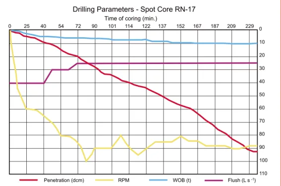
Data recording of drilling parameters was logged and made available for future analysis. A graphical output of drill- ing parameters is available to the driller during operation. Figures 4–6 have greatly assisted in allowing a full core barrel penetration to be achieved without any resistance to penetrate further.
Flush rate while coring was varied to observe any differ- ence in core recovery results and recorded core barrel temperatures. The flush rates available while coring are very high compared to other core barrels, and high flush rates can affect both core recovery and penetration rates by washing away core and lifting the bit off cutting contact with the bottom, respectively. We used 40 L s -1 while spudding in
and for the first five minutes, then it was cut to 30 L s -1 and
after a few more minutes was reduced to 25 L s -1 for the
remainder of the coring run. No marked changes in bit weight or penetration rate were observed, so provided the formation is competent, there should be no problems in trying to core with full flush capability in boreholes which have a higher ambient temperature, such as thatanticipated at Krafla. This suggests that the bit design meets require-ments and allows for full flow through the waterways and then uphole without causing undue pressure build-up at the bit face or in the core barrel head ports.
It was not possible to reach and maintain high rotational speed (>100 rpm) on the drill string without excessive vi- bration and string movement. This could be due to a number of factors, but certainly the vertical to inclined borehole configuration would have something to do with this. However, rotation without excessive vibration or string movement was possible within the operating bit
para-Drilling Parameters - Spot Core RN-17
Time of coring (min.)
0 25 40 54 72 90 101 114 122 137 152 167 187 209 229 0
10
20
30
40
50
60
70
80
90
100
110
Penetration (dcm) RPM WOB (t) Flush (L s )-1
Technical Developments
ment of stabilizers than would otherwise occur, and it may be that for inclined coring (not routinely planned) a set of stabi-lizer rings may have to be incorporated into the outer, rather than the inner, core barrel sections.
Acknowledgements
The work was carried out to an agreed plan, schedule, and extremely tight timescale. The successful outcome is in meters. Generally if low-end
rpm is used, then high-end bit weights have to be applied to maintain acceptable pene-tration and smooth opera-tion.
Spot Coring Results
Indications while coring suggested that core was being collected, but it was not until the pull-off force at the base of the coring run increased markedly then dropped back that it could be said that there was core caught inside the core barrel (which had to be broken off). Then it was not until the string was tripped out, the core barrel dismantled, and the core pumped out of the inner tubes that the full measure of the success of the core run was established.
Core recovery was excel-lent despite the fact that the core barrel was being run in an inclined borehole and the rock was fractured with many wedge-shaped planar frac- tures which could have easily caused core jamming. Figures 7 and 8 show the nature of the core collected. The cored section consisted of a hyaloclastite breccia, thoroughly altered to green-schist facies mineralogy. Apparently, this breccia was deposited in shallow marine environment, despite the fact it is now at 2.500 m depth below the surface. The age of this breccia is one of the key questions to be unraveled to
allow estimation of the subsidence rate in the middle of the Reykjanes rift zone. The drill core is now being studied, and first results have been published by Friðleifsson and Richter (2010).
In the 35°-inclined RN-17 B test hole, the inner core barrel stabilizers could not operate properly as centralizers, since wear was always on the side “lying down”. Although this did not materially affect the coring, it induced more
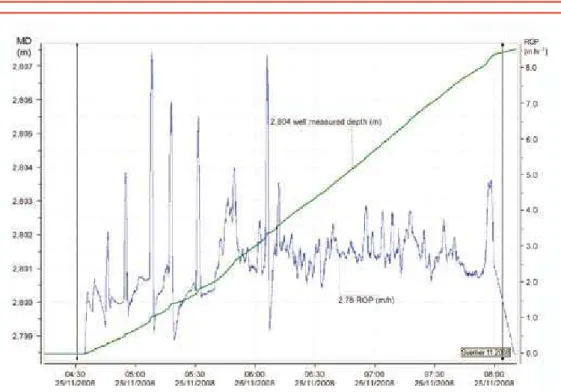
refurbish-Figure 6. Time-coring rate (m h-1) diagram – 27 November 2008, 4:34–8:00, at 2800 m depth. Core recovery was close to 100% of 4" core. Average coring rate 2.6 m h-1. The green curve shows increasing depth.
Authors
Alexander C. Skinner, ACS Coring Services, 13 Riccarton Drive, Currie, Edinburgh, EH14 5PN, Scotland, U.K., e-mail: [email protected].
Paul Bowers, Rok-Max Drilling Tools Ltd., P.O. Box 87, Truro, Cornwall, TR3 7ZQ, U.K., e-mail: paulbowers@ rokmax.com.
Sverrir Þórhallsson, Iceland Geosurvey (ISOR),
Grensasvegur 9, Reykjavik, IS-108, Iceland, e-mail: s@isor. is.
Guðmundur Ómar Friðleifsson, HS Orka hf, Brekkustígur 36, 260 Reykjanesbær, Iceland, e-mail: [email protected].
Hermann Guðmundsson, Iceland Geosurvey (ISOR),
Grensasvegur 9, Reykjavik, IS-108, Iceland, e-mail: hg@ isor. is.
Related Web Links
http://www.icdp-online.org/
http://iddp.is/iddp-papers-at-wgc-2010/
Photo Credits
Figs. 2, 3, 7, and 8 by G.Ó. Friðleifsson, H.S. Orka, and IDDP-PI
large measure due to the thought put into the core barrel and bit designs by ROK-MAX and GEOGEM companies and to the efforts of H. Guðmundsson regarding site management of equipment, logistics, and suitable location to set up and service the core barrels. The IDDP committees of Sciences Application Group of Advisors (SAGA) and Deep Vision approved the case for core barrel procurement, which was overseen by Bjarni Palsson of Landsvirkjun. At site the drill-ing manager, Steinar Már Þórisson, worked with us and both shift crews of the Jardboranir Ltd. drill rig Tyr to allow an excellent test with a good outcome.
We also acknowledge grants from ICDP to G.Ó. Friðleifsson and W.A. Elders, for having the core barrel designed and built and additionally the U.S. NSF (award number EAR-0507625 to Elders) for financing the test coring at Reykjanes. And last but not the least, we thank the IDDP consortium for accepting and supporting the imple-mentation of the core barrel manufacture for scientific pur-poses.
References
Elders, W.A., and Fridleifsson, G.O., 2005. The Iceland Deep Drilling Project - scientific opportunities. Proc. World Geothermal Congr., Antalya, Turkey, 24–29 April 2005, paper 0626, 6 pp.