Abstract
An assessment of the efficiency and convergence characteristics of a four-node quadrilateral plate finite element in the analysis of lami-nated composites is performed. The element, which is suitable for global response analysis, is developed in the framework of the strain gradient notation such that its modeling capabilities as well as modeling deficiencies can be physically interpreted by the analyst during the formulation process. Thus, shear locking typically en-countered in four-noded plate elements is identified as caused by spurious terms which appear in the shear strain polynomial expan-sions. These identified spurious terms are removed a priori such that shear locking does not occur during numerical analysis and numerical remedies do not need to be applied. Stress solutions for different laminated plates are presented to demonstrate that the corrected model converges well to reference solutions.
Keywords
Laminated composite plates, First-order shear deformation theory, Strain gradient notation, Shear locking, Parasitic shear, Finite element method.
On a Four-Node Quadrilateral Plate for Laminated Composites
1 INTRODUCTION
Composite materials are formed by the combination of two or more materials on a macroscopic scale such that they have better engineering properties than conventional materials. For instance, increase in stiffness and strength, and reduction in weight are usually desirable when designing a composite material for structural applications. The most common type of composite material is that which is comprised of reinforcement fibers embedded in a matrix material. Modern composites are manufactured in the shape of thin laminae or layers. When two or more laminae are stacked to form a single structure the composite material is called laminated composite. Laminated composites find structural applications in various industry sectors such as aerospace, aeronautic, automotive, and sports equipment among others.
João Elias Abdalla Filho a, b, d, * Ivan Moura Belo c
John Otto Dow d
a Programa de Pos-Graduacao em
Engenharia Mecanica/Pontificia Universidade Catolica do Parana [email protected]
b PPGEC/UTFPR. [email protected]
c PPGEM/UTFPR. [email protected]
d University of Colorado Boulder
* Corresponding author
http://dx.doi.org/10.1590/1679-78253663
The finite element method has been widely used for analyzing laminated composite structures. Early isoparametric models based on the first-order shear deformation theory (FSDT) were devel-oped by Mawenya and Davies (1974), and by Panda and Natarajan (1979). FSDT is the simplest theory which is capable of modeling laminated composites accurately because transverse shear plays an important role in such structures. Thorough descriptions of FSDT are found in the books of Vinson and Sierakowski (2002) and Reddy (2004). The theory is summarized later in this article.
Higher-order shear deformation theories (HSDT) have also been developed in order to improve the accuracy in modeling laminated composites. Accounts on the development of such theories and finite element models associated to them can be found in the works of Lo et al. (1977), Reddy (1989), Singh and Rao (1995), and Bose and Reddy (1998). The reader is also referred to the works of Sheikh and Chakrabarti (2003) and Aagaah et al. (2003) for finite element models based on HSDT.
Most works cited above associate a first or higher-order plate theory to the equivalent-lamina assumption. Under this assumption, the laminated composite is modeled as a single-lamina plate having as its properties averages of the properties of the various laminae that comprise the lami-nate. As this assumption is considered limiting depending on the purpose of the analysis, layerwise theories were built and computational models associated to them have been developed. Layerwise models consider each lamina of the laminate and its properties discretely, and they may be FSDT or HSDT-based. As example of plate elements developed according to layerwise theories, we cite the works of Botello et al. (1999), Moleiro et al. (2010), Mantari and Soares (2013), and Pandey and Prandyumna (2015). The drawback of these and layerwise models in general is that they become too costly when the laminate is composed of many laminae. Thus, other alternatives for analyzing laminated composites accurately and efficiently have been sought. We find appealing the Refined Zigzag Theory (RZT). RZT is FSDT-based and employ piecewise-linear zigzag functions that pro-vide better representations of the deformation states of transverse shear-flexible plates. RZT has very likely been introduced by Tessler et al. (2010), and follow-up results have been done by Gher-lone et al. (2011), Versino et al. (2013), and Eijo et al. (2013).
The plate element discussed in this article is formulated according to FSDT and the single-lamina assumption. No refined theories or strategies are employed, but accuracy and efficiency are sought here via a non-conventional finite element formulation procedure. The element is formulated using strain gradient notation, a physically interpretable notation, which has been developed by Dow (1999). The objective here is to show that the model is capable of producing accurate stress results for laminated composite plate problems once the inherent spurious terms which are responsible for shear locking are removed. In the remaining of the article, the FSDT and equivalent-lamina assumption for laminated composites are briefly reviewed, the four-node plate element is formulated and its modeling characteristics are discussed, results are presented and conclusions are drawn.
2 FSDT AND EQUIVALENT-LAMINA ASSUMPTION FOR LAMINATED COMPOSITES
lami-nated composites are usually thin structures, transverse shear effects are important and have to be accounted for in the description of the behavior of laminates (for instance, transverse shear is a key factor in delamination). Thus, FSDT must be adopted in the modeling of laminated composites as opposed to CPT.
The laminate is modeled as a single, orthotropic lamina with averaged mechanical properties under the equivalent-lamina assumption. Thus, all laminae must be assumed to be completely bonded together, and relative slippage cannot occur. As a result, the behavior of the laminate can be represented by the behavior of its middle surface. Also, the normal-to-the-middle surface compo-nent of stress is neglected and the laminate is thus in a state of plane stress.
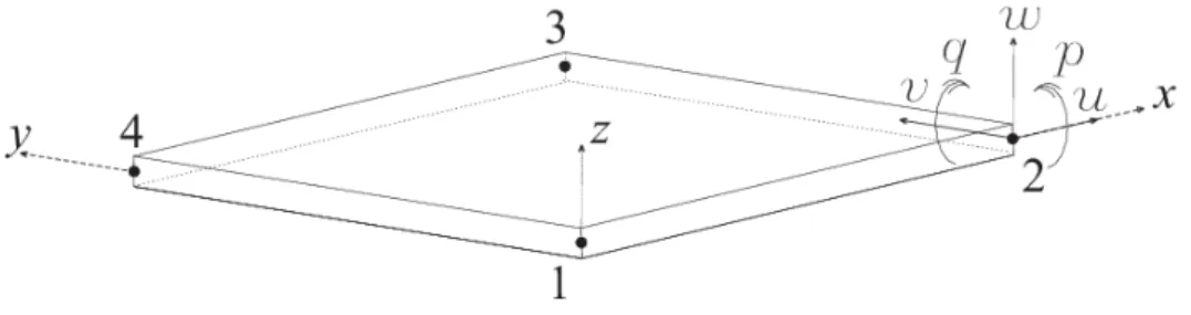
Figure 1 represents a FSDT laminated plate where the displacements that the laminate can un-dergo are indicated in the corner number 2. In-plane displacements in the x- and y-direction are represented by u and v, respectively, while the displacement in the z-direction is represented by w. Rotations in the x and y directions are represented by q and p, respectively. The kinematic rela-tions of the plate are the following:
x y z
u
x y zq
x yu , , 0 , , (1)
x y z
v
x y zp
x yv , , 0 , , (2)
x y wow , (3)
z z y x u y x q
, ,
, (4)
z z y x v y x p
, ,
, (5)
where uo and vo are the middle surface in-plane displacements, and z is the coordinate which is
associated to the thickness of the laminate.
Figure 1: Displacements of the FSDT laminated plate.
q w p w p q z zp zq v u v u x y x y y x x o y o y o x o xz yz xy y x , , , , , , 0 0 , , , ,
(6)where the first vector on the right-hand side represents membrane strains while the second vector represents plate bending strains.
3 FOUR-NODE PLATE ELEMENT
The element is formulated using the strain gradient notation procedure. Strain gradient notation is a physically interpretable notation which explicitly relates the displacements to the kinematic quan-tities of the continuum. Such kinematic quanquan-tities are rigid body modes, strains, and first-order and higher-order derivatives of strains, and they are generally referred to as strain gradients. The rela-tionships between displacement components and strain gradients are obtained via an algebraic pro-cedure in which the physical contents of the coefficients of the approximating functions are deter-mined. The procedure is fully described and results are tabulated in Dow (1999). Such procedure has been applied to the four-node plate element in an earlier paper (Abdalla Filho et al., 2008). In that paper, the formulation was presented in great level of detail where the algebraic procedure which led to the identification of the physical contents of the polynomial coefficients was performed. In the present paper, a comprehensive discussion on the procedure for identifying and eliminating the spurious terms is provided. A close relation between the procedure and the procedure of re-duced-order integration used in the four-node isoparametric plate element is also provided. The limitation of the one-point integration strategy is pointed out as it induces another type of error. The new numerical solutions presented here make very clear that the results for thin plates are very accurate after the correct elimination of the spurious terms is performed. Other references of strain gradient notation are the doctoral thesis of Byrd (1988), Abdalla Filho (1992) and Hamernik (1993) at the University of Colorado Boulder, and the articles of Dow et al. (1985), Dow and Byrd (1988), Dow and Byrd (1990), Dow and Abdalla Filho (1994), Abdalla Filho and Dow (1994), and Abdalla Filho et al. (2006).
Due to the physically interpretable character of the strain gradient notation, modeling charac-teristics of the finite element are made apparent since the early steps of the formulation. This allows for the identification of spurious terms which are responsible for modeling errors. Sources of shear locking in the four-node plate element will be shown in this section.
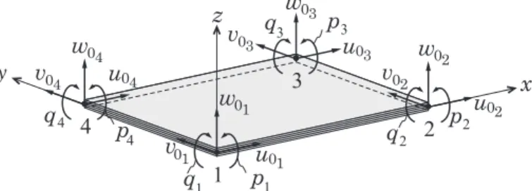
The four-node plate element is defined as having five degrees-of-freedom per node; namely, the in-plane displacements uo and vo, the out-of-plane displacement wo, and the rotations q and p, as
Figure 2: Four-node plate element.
The displacement approximating functions already written in strain gradient notation are:
xz
xyz
yzz q xy y r x u z y x u o y xz x yz z xy o yz x o z x o xz o y x o xy o x o 2 / 2 / 2 / , , , , , , , , (7)
yz
xyz
xzz p xy y x r v z y x v o y xz x yz z xy o xz y o z y o yz o x y o y o xy o 2 / 2 / 2 / , , , , , , , , (8)
x
y
w
q
x
p
y
xy
w
o y xz x yz z xy o yz o xzo
/
2
/
2
/
2
,
,
,
, (9)
x
y
q
x
y
xy
q
o yz x o y xz x yz z xy o z x oxz
/
2
, , , ,/
2
,,
(10)
x
y
p
x
y
xy
p
o xz y o z y o y xz x yz z xy oyz
/
2
, , ,/
2
, ,,
(11)Inspection of these expressions reveals that the displacements are expressed in terms of rigid body movements, constant normal and shear strains, first-order and second-order derivatives of normal strains, and first-order derivatives of shear strains. These quantities comprise the set of twenty deformation modes that form the basis of the four-node plate element. For clarity, they are listed below:
u o, v o, wo, r o, p o, q o rigid body modes
xzo o yz o xy o y ox
,
,
,
,
constant strains
x,yo,
x,zo,
y,xo,
y,zo first-order normal strain gradients
xy,z o,
yz,xo,
xz,yo first-order shear strain gradients
x,yzo,
y,xz second-order normal strain gradientsThe strains are obtained by the derivatives of displacements according to elasticity definitions:
y
z
yz
o yz x o z x o y x o x
x
,
,
,
(12)
x
z
xz
o xz y o z y o x y o y
y
,
,
,
(13)1 z x y 0 u1 v w 1 1 2 2 2 3 3 3 4 4 4 01 01 0 u2 0 w2 0 v2 0 w3 0 u3 0 v3 0 w4 0
v 4 u04
x
y
z
yz
xz
o yz x o xz y o z xy o x y o y x o xyxy
,
,
,
,
,
(14)
x
y
xy
o xz y o z y o x yz o yz
yz
,
,
,
(15)
y
x
xy
o yz x o z x o y xz o xz
xz
,
,
,
(16)Inspection of the strains expansions above will reveal a-priori the capabilities of the element in representing deformation, but also any deficiencies that might exist. The literature discusses broadly that four-node plate elements might behave poorly due to shear locking, which might be briefly explained as an artificial stiffening of the model that occurs when shear strain energy increases un-duly. It appears that shear locking was first reported in Zienkiewicz et al. (1971), and reduced-order integration was devised to circumvent the problem. Reduced-order integration schemes have the purpose of not integrating the terms in the stiffness matrix which are associated to this spurious shear strain energy. As it was soon detected that uniform reduced-order integration schemes were not fully effective, selective reduced-order integration schemes were then proposed as an improve-ment over the uniform schemes. The reader is referred to the pioneering works by Pawsey and Clough (1971), and by Hughes et al. (1978). However, such selective schemes introduced spurious zero-energy modes, which motivated the development of the “Heterosis” element by Hughes and Haroum (1978). Particularly for the case of four-node plates, the selective reduced integration pro-cedure applied by Hughes et al. (1977) gave rise to two spurious zero-energy modes. One solution was presented by Belytschko et al. (1981) where a scaling of the shear stiffness matrix was applied. Following these initial endeavours, many other finite element formulation strategies have been de-vised to this date to overcome shear locking. A review of such methodologies is not the purpose of the present article.
It is our intention now to identify precisely what are the sources of shear locking in four-node plate elements as we make use of the strain gradient notation. This will be done considering the strain expansions expressed via Equation 12 through Equation 16. It is logical that the sources of shear locking reside in the strain expansions as the stiffness matrix stems from the strain energy. Consider that each term in a strain expansion should be a term of the Taylor series expansion asso-ciated to that strain. That is, the terms should be that particular strain evaluated at a given origin and derivatives of that strain. This is what it is observed in inspecting Equation 12 and Equation 13. The right-hand sides of these equations are composed of terms which belong to the Taylor series of the normal strains. Thus, we may assert that those expressions do not contain any erroneous terms.
Let us next consider Equation 14, which expresses the in-plane shear strain. The expansion is seen to possess six terms, four of which are associated to normal strains. These terms are
Equation 15 and of Equation 16 are also spurious. That is,
x,zo,
y,zo,
x,yzo,
y,xzoare sourcesof shear locking as they are flexural terms and will increase transverse shear strain energy unduly when activated during analysis. Thus, a total of six spurious terms are contained in the shear strain expansions of the four-node plate element. Due to their deleterious effects in finite element analysis and their nature, such terms are called parasitic shear terms. This a-priori identification of the number and accurate nature of those terms is very difficult if a conventional notation is employed. This shows that strain gradient notation gives us full understanding of the shear locking sources.
The next task is the elimination of shear locking, which is essential for the good behavior of the element. First, let us describe what happens if reduced-order integration were applied. The common approach would be the use of one-point integration to integrate the shear part of the stiffness ma-trix. As noted by Byrd (1988), one-point integration eliminates the terms in x and y in the shear strain expressions. Thus, the four spurious terms in γxy are successfully eliminated, but also the terms
yz,x o and
xz,y oin γyz and γxz, respectively, are eliminated. Clearly, such terms arelegit-imate and should not be eliminated. However, as the one-point quadrature is not capable of choos-ing terms, it introduces two spurious zero-energy modes when those two shear strain terms are elim-inated along with the parasitic shear terms. This is precisely what happened in the work of Hughes et al. (1977). Next, one major advantage in employing strain gradient notation is demonstrated. Inspection of Equations 14, 15 and 16 has precisely identified the parasitic shear terms of the four-node plate. As those are the sources of shear locking, they must be eliminated. So, we simply re-move those terms from the shear strain expansions to generate the following correct expressions:
z
o z xy o xy
xy
,
(17)
x
o x yz o yz
yz
,
(18)
y
o y xz o xz
xz
,
(19)When the strain energy is formulated using these expressions, a stiffness matrix free of parasitic shear terms is built, and shear locking effects do not occur. Further, spurious zero-energy modes are not introduced.
Now that the parasitic shear terms have been eliminated, we proceed on with the formulation of the stiffness matrix of the four-node plate element for laminated composites. The strain energy of the laminate is obtained by the sum of the strain energies of the comprising laminae:
(20)
d
sg (21)
Tsg
sg (22)where and are transformation matrices relating displacement coordinates and strains to the generalized coordinates, respectively. Matrix contains the linearly independent vectors which are associated to the twenty deformation modes of the element. Matrix may also be written before the elimination of the parasitic shear terms. That is, the element may be formulated in two versions, namely; a version containing parasitic shear terms, and a corrected version. This is actually what it is done in this work in order to show locking effects and the efficiency of the cor-rected element.
Equation 21 is inverted and substituted in Equation 22 to eliminate the explicit dependence on the strain gradient vector. The resulting equation is substituted into Equation 20 to yield the fol-lowing form of the strain energy of the laminate in strain gradient notation:
d
T
Q
T d
dU k
n
k k k
sg k T k sg T T 1 1 2 1
(23)The term between parentheses is called strain energy matrix and it is usually represented by . The terms in its principal diagonal quantify the strain energy content of each deformation mode while the off-diagonal terms quantify the strain energy content of the various coupling of de-formation modes. may be rewritten as:
U
T
Q
T dZkdAk sg k A n k k Z k Z T k sg
M
1 1 (24)
where the limits Zk-1 and Zk represent the bottom and top coordinates of lamina k. Integration over
the thickness of the laminate yields the laminated composite´s stiffnesses:
n k k k k ijij Q Z Z
A
1 1 (25)
n k k k k ijij Q Z Z
B 1 2 1 2 2 1 (26)
n k k k k ijij Q Z Z
D 1 3 1 3 3 1 (27)
n k k k k ijij K Q Z Z
A
1 1
*
(28)
multi-plied by the shear correction factor K. The usual value of K is 5/6 (Reddy, 2004), which is adopted in this work.
Finally, as the strain energy in terms of the stiffness matrix is given by:
d
K
dU T
2 1
(29)
it can be concluded that the stiffness matrix in strain gradient notation is computed as:
1M T
U
K
(30)whose components can be (and usually are) obtained symbolically, avoiding numerical integration procedures during the finite element analysis. This is another advantage of the strain gradient nota-tion as it renders the analysis computanota-tionally more efficient. For brevity, we do not present the explicit form of the stiffness matrix. The formulation just presented has been implemented in a Fortran code named LAMFEM, which was developed in Abdalla Filho (1992), and it is employed in the analyses to be presented and discussed in the following section.
4 NUMERICAL EXPERIMENTS
Three numerical experiments are performed here. In each, a square plate having edges equal to 1.0 m is analyzed. In the first experiment, an isotropic single-layer plate with material properties E = 75 GPa and ν = 0.30 is analyzed whereas laminated composite plates are analyzed in the other two experiments. Laminae in the latter two experiments are made of Graphite-Epoxy. The correspond-ing material properties are: Ex = Ey = 175 GPa, Gxy = Gxz = 3.5 GPa, Gyz = 1.4 GPa, and νxy =
0.25. As shear locking is more evident for thin structures, we have chosen to analyze plates with aspect ratio (side length/thickness) a/h = 100. Exception is made in the first experiment where transverse displacement results are also computed for the relations a/h = 20 and 50. Five uniform meshes are used, namely; 2x2, 4x4, 8x8, 16x16, and 32x32, and solutions for displacements and through-the-thickness stresses are provided both with the model containing parasitic shear terms and with the corrected model. Only a few stress components are selected as they are representative of the overall behavior of the laminated composite models. Comparison between both solutions is made to show the convergence characteristics of the corrected model and the effectiveness of the procedure described for the elimination of parasitic shear terms. Solutions are compared to analyti-cal solutions as well. Such analytianalyti-cal solutions are indicated in the plots as FSDT, while solutions with parasitic shear terms are indicated as with/PS, and solutions corrected for parasitic shear are indicated as wout/PS.
4.1 Experiment #1
shear and the model containing parasitic shear. Numbers in parentheses are those which correspond to the model containing parasitic shear.
Maximum transverse displacements
a/h Analytical
solution 2x2 4x4 8x8 16x16 32x32
20 0.023570 0.024562 0.024686 0.025055 0.025384 0.025384
(0.005592) (0.012940) (0.020303) (0.023966) (0.023966)
50 0.368286 0.372085 0.370535 0.372085 0.373837 0.373837
(0.016582) (0.055057) (0.150426) (0.272009) (0.272009)
100 2.946286 2.963164 2.946400 2.952242 2.957830 2.957830
(0.034102) (0.123088) (0.429235) (1.188999) (1.188999)
Table 1: Transverse displacements for isotropic plate.
In general, it may be stated that results provided by the corrected model approximate reasona-bly well the analytical solution values for all three side length-thickness relations. Taking the results of the last column (32x32 mesh), percent errors are 7.69%, 1.51% and 0.39%. Now, results provided by the model containing parasitic shear are inferior (except for the relation a/h = 20), and they get worse as the plate gets thinner. Percent errors are now 1.68%, 3.86% and 40.35%. Another im-portant result is obtained when we look at the values provided by the coarse meshes. For example, values associated with the 2x2 mesh show how deleterious the effects of parasitic shear are. Values in parentheses are totally in error. However, after elimination of parasitic shear, the coarse mesh provides very good displacement results.
4.2 Experiment #2
Here we analyze a simplysupported, symmetric crossply laminated plate with lamination scheme -0°/90°/0°. The plate is loaded by a uniform load of value qo = 10 N/m2. Solutions are obtained for
the normal stresses σxx, which are calculated at the plate´s center point, for the in-plane shear
stresses τxy, which are calculated at one border´s mid-point, and also for the transverse shear
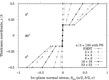
stress-es τxz, which are calculated at another border´s mid-point. Figure 3a and Figure 3b show the
distri-bution of σxx along the thickness of the plate for the model with parasitic shear terms (with/PS)
and for the corrected model (wout/PS), while Figure 3c shows the convergence behavior of both models. Table 2 contains the highest percent errors calculated in each analysis of σxx.
Figure 3a: Symmetric cross-ply laminate. Normal stresses σxx computed with parasitic shear.
Figure 4a and Figure 4b show the distribution of the in-plane shear stresses τxy along the
thick-ness of the plate for the model with parasitic shear terms (with/PS) and for the corrected model (wout/PS), while Figure 4c shows the convergence behavior of both models. These stresses are cal-culated at the center point of one of the borders of the plate. The highest percent errors calcal-culated in each analysis of τxy are also shown in Table 2.
Here results also show that the models with parasitic shear (with/PS) present a strong locking effect and that further refinement would be necessary for their solutions to approach the analytical FSDT solution. Errors range from 99.11 % in the coarser mesh (2x2) to 21.98 % in the finer mesh (32x32). However, the model without parasitic shear (wout/PS) presents good convergence to the analytical solution as errors range from 76.31% to 1.12%. The convergence plots show the good monotonic convergence characteristics of the corrected model and the slow convergence of the mod-el containing parasitic shear.
Figure 3c: Symmetric cross-ply laminate. Convergence of normal stresses σxx.
Figure 4a: Symmetric cross-ply laminate. Shear stresses τxy computed with parasitic shear.
Figure 4c: Symmetric cross-ply laminate. Convergence of shear stresses τxy.
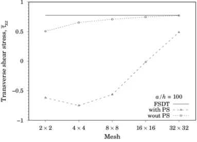
Figure 5a and Figure 5b show the distribution of τxz along the thickness of the plate for the
model with parasitic shear terms (with/PS) and for the corrected model (wout/PS), while Figure 5c shows the convergence behavior of both models. Table 2 also contains the highest percent errors calculated in each analysis of τxz. It is seen that the parasitic shear terms have a strong deleterious
effect, providing qualitatively as well as quantitatively wrong solutions. The solution is qualitatively wrong because it tends toward the opposite direction of the FSDT solution. Huge percent errors in Table 2 represent that erroneous behavior. It is only the finer mesh that presents the correct quali-tative behavior. However, the error of 36.82% is still very high. Thus, this erroneous solution behav-ior is a strong argument in favor of eliminating parasitic shear terms a-priori instead of trusting shear locking effects reduction through refinement. When parasitic shear is eliminated, the solution converges well to the analytical solution as shown in Figure 5b. The highest error contained in the finer mesh is only 0.47%. The convergence curves corroborate these findings as shown in Figure 5c.
Figure 5b: Symmetric cross-ply laminate. Transverse shear stresses τxz computed without parasitic shear.
Figure 5c: Symmetric cross-ply laminate. Convergence of transverse shear stresses τxz.
Percent errors in stress components
[0°/90°/0°] σxx τxy τxz
a/h Meshes with/PS wout/PS with/PS wout/PS with/PS wout/PS
100
2x2 98.81 36.92 99.11 76.31 180.05 34.72 4x4 93.06 4.37 94.64 36.90 196.97 15.50 8x8 75.90 1.10 80.03 14.83 173.05 8.52 16x16 43.10 0.17 50.72 4.96 102.10 3.49 32x32 14.90 0.08 21.98 1.12 36.82 0.47
4.3 Experiment #3
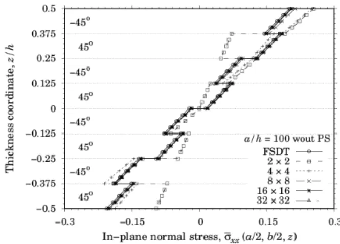
As the third and last experiment, we analyze a simply-supported (SS2), anti-symmetric angle-ply laminate with lamination scheme [-45°/45°4 (eight laminae), and subjected to the same uniform
load of the previous experiment. Again, solutions for the normal stresses σxx are calculated at the
plate´s center point while solutions for the shearing stresses τxy and τxz are calculated at borders
mid-points. Table 3 contains the highest percent errors computed with respect to the FSDT analyt-ical solution for solutions with and without parasitic shear effects. Figure 6a through Figure 6c show the results for σxx. Inspection of these figures allied to the findings from the previous
experi-ments allows us to assert that the model containing parasitic shear terms presents a slow conver-gence rate and will require more refinement, and that the model corrected for parasitic shear con-verges rather quickly to the correct solution. We observe that the model corrected for parasitic shear converges from above, which is clearly shown by the convergence plots of Figure 6c. Neverthe-less, convergence is monotonic. Percent error values of Table 3 corroborate those findings as the finer mesh of the model containing parasitic shear has an error of 7.11% while the finer mesh of the corrected model has an error of only 1.72%.
Figure 6a: Anti-symmetric angle-ply laminate. Normal stresses σxx computed with parasitic shear.
Figure 6c: Anti-symmetric angle-ply laminate. Convergence of normal stresses σxx.
Percent errors in stress components
[-45°/45°]4 σxx τxy τxz
a/h Meshes with/PS wout/PS with/PS wout/PS with/PS wout/PS
100
2x2 97.52 26.89 98.33 70.58 217.20 38.59 4x4 86.93 24.79 90.65 30.12 237.08 19.59 8x8 61.09 6.27 69.87 11.71 196.98 11.33 16x16 26.82 2.46 40.05 5.33 101.84 3.48 32x32 7.11 1.72 20.94 4.08 25.21 1.44
Table 3: Percent errors in stress solutions of the anti-symmetric angle-ply laminate.
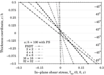
The in-plane shear stresses τxy results are presented in Figure 7a through Figure 7c. Once again,
it appears that the parasitic shear terms play an important role in delaying convergence to the cor-rect solution. As shown in Table 3, percent error in the model containing parasitic shear ranges from 98.33% to 20.94%. That is, refinement does a very poor job in eliminating the deleterious ef-fects of parasitic shear. After the a-priori elimination of parasitic shear, error ranges from 70.58% to 4.08%. The convergence plots in Figure 7c clearly show total discrepancy between both solutions. The model containing parasitic shear presents that characteristic slow convergence behavior also presented previously while the corrected model presents monotonic convergence.
The transverse shear stresses τxz results are shown in Figure 8a through Figure 8c, and the
Figure 7a: Anti-symmetric angle-ply laminate. Transverse shear stresses τxy computed with parasitic shear.
Figure 7b: Anti-symmetric angle-ply laminate. Transverse shear stresses τxy computed without parasitic shear.
Figure 8a: Anti-symmetric angle-ply laminate. Transverse shear stresses τxz computed with parasitic shear.
Figure 8b: Anti-symmetric angle-ply laminate. Transverse shear stresses τxz computed without parasitic shear.
5 CONCLUSIONS
The formulation of a four-node plate element using a physically interpretable notation, called strain gradient notation, was presented for the analysis of laminated composites which are based on the equivalent-lamina assumption. The modeling characteristics of the element could be investigated as the notation allows for a clear physical understanding of the comprising terms of the displacement and strain polynomials. This capability allowed for identifying that spurious terms are present in the three shear strain polynomials of the element, and, using theoretical arguments based on their natures, such spurious terms were a-priori recognized as being the sources of shear locking. As they are terms associated to normal strains which are present in shear strain expressions, the spurious terms were referred to here as parasitic shear terms. Further, it was pointed out that the procedure for precluding the effects of shear locking via the a-priori elimination of the parasitic shear terms is completely effective as it is done without the introduction of any spurious zero-energy modes. As opposed to reduced-order integration techniques, the procedure allowed by strain gradient notation removes only the terms which are spurious. Legitimate terms that comprise the shear strain expan-sions are maintained. Also, the strain gradient formulation procedure allows for the symbolic inte-gration of the stiffness matrix, removing the necessity of numerical inteinte-gration during analysis. All these considered, strain gradient notation has advantages over other formulation procedures.
Three numerical experiments were performed to show both the deleterious effects of shear lock-ing in laminated composite problems and that the corrected model provides accurate solutions. Thus, all experiments were run with two versions of the model, namely; a version containing the parasitic shear terms and a version after elimination of the parasitic shear terms (corrected model). Overall results showed that shear locking strongly occurs when the parasitic shear terms are pre-sent, and that convergence is prevented. Results for transverse shear stresses showed that the errors introduced by parasitic shear may be of a qualitative nature as well as of a quantitative one. In that sense, refinement may not be sufficient to produce a convergent solution as artificial stiffening or locking is not the only phenomenon. Solutions go in the wrong direction as refinement is performed. Further, results provided by the corrected model were compared to analytical results and very good accuracy was obtained. Very small numerical errors such as 0.08% and 0.47% were registered. Such results allow for the conclusion that the model is capable of providing very accurate results for stresses.
A few aspects are to be investigated in further studies. The most immediate one is to repeat these analyses using models which take advantage of the symmetry of the domains. This was not done here for simplicity. But, it is to be expected that better results could be attained as a quarter of the plate would be modeled by the same meshes which modeled the entire domain in this work. Also, it would be important to test the element for distortion. There is no reason why the element should not behave well when distorted, but it remains to be shown. For instance, circular plates and plates with cutouts are important problems that require distortion. Further, vibration and buckling analysis are natural next steps.
References
Abdalla Filho, J.E. (1992). Qualitative and discretization error analysis of laminated composite plate models, Ph.D. Thesis, University of Colorado Boulder, United States of America.
Abdalla Filho, J.E., Dow, J.O. (1994). An error analysis approach for laminated composite plate finite element mod-els. Computers and Structures 52(4): 611-616.
Abdalla Filho, J.E., Fagundes, F.A., Machado, R.D. (2006). Identification and elimination of parasitic shear in a laminated composite beam finite element. Advances in Engineering Software 37: 522-532.
Abdalla Filho, J.E., Belo, I.M., Pereira, M.S. (2008). A laminated composite plate finite element a-priori corrected for locking. Structural Engineering and Mechanics 28(5): 603-633.
Belytschko, T., Tsay, C.S., Liu, W.K. (1981). A stabilization matrix for the bilinear Mindlin plate element. Com-puter Methods in Applied Mechanics and Engineering 29: 313-327.
Bose, P., Reddy, J.N. (1998). Analysis of composite plates using various plate theories, part 2: finite element model and numerical results. Structural Engineering and Mechanics 6(7): 727-746.
Botello, S., Onate, E., Canet, J.M. (1999). A layer-wise triangle for analysis of laminated composite plates and shells. Computers and Structures 70: 635–646.
Byrd, D.E. (1988). Identification and elimination of errors in finite element analysis, Ph.D. Thesis, University of Colorado Boulder, United States of America.
Dow, J.O., Ho, T.H., Cabiness, H.D. (1985). A generalized finite element evaluation procedure. Journal of Structural Division, ASCE 111: 435-452.
Dow, J.O., Byrd, D.E. (1988). The identification and elimination of artificial stiffening errors in finite elements. International Journal for Numerical Methods in Engineering 26: 743-762.
Dow, J.O., Byrd, D.E. (1990). Error estimation procedure for plate bending elements. AIAA Journal 28(4): 685-693. Dow, J.O., Abdalla, J.E. (1994). Qualitative errors in laminated composite plate models. International Journal for Numerical Methods in Engineering 37: 1215-1230.
Dow, J.O. (1999). A unified approach to the finite element method and error analysis procedures, Academic Press (San Diego).
Eijo, A., Onate, E., Oller, S. (2013). A four-node quadrilateral element for composite laminated plates/shells using the refined zigzag theory. International Journal for Numerical Methods in Engineering 95(8): 631-660.
Gherlone, M., Tessler, A., Di Sciuva, M. (2011). Co beam elements based on the refined zigzag theory for multi-layered composite and sandwich laminates. Composite Structures 93(11): 2882-2894.
Hamernik, J.D. (1993). A unified approach to error analysis in the finite element method, Ph.D. Thesis, University of Colorado Boulder, United States of America.
Hughes, T.J.R., Taylor, R.L., Kanoknukulchai, W. (1977). A simple and efficient finite element for plate bending. International Journal for Numerical Methods in Engineering 11: 1529-1543.
Hughes, T.J.R., Cohen, M. (1978). The “Heterosis” finite element for plate bending. Computers and Structures 9: 445-450.
Hughes, T.J.R., Cohen, M., Haroun, M. (1978). Reduced and selective integration techniques in finite element analy-sis of plates. Nuclear Engineering and Design 46: 203-222.
Kim, K.D., Lee, C.S., Han, S.C. (2007). A 4-node co-rotational ANS shell element for laminated composite struc-tures. Composite Structures 80: 234-252.
Lo, K.H., Cristensen, R.M., Wu, E.M. (1977). A high-order theory of plate deformation, part 2: laminated plates. Journal of Applied Mechanics 44(4): 669-676.
Mawenya, A.S., Davies, J.D. (1974). Finite element bending analysis of multilayer plates. International Journal for Numerical Methods in Engineering 8: 215-225.
Moleiro, F., Mota Soares, C.M., Mota Soares, C.A., Reddy, J.N. (2010). Layerwise mixed least-squares finite element models for static and free vibration analysis of multilayered composite plates. Composite Structures 92: 2328-2338. Panda, S.C., Natarajan, R. (1979). Finite element analysis of laminated composite plates. International Journal for Numerical Methods in Engineering 14: 69-79.
Pandey, S., Prandyumna, S. (2015). A new Co higher-order layerwise finite element formulation for the analysis of laminated and sandwich plates. Composite Structures 131: 1-16.
Pawsey, S.F., Clough, R.W. (1971). Improved numerical integration of thick slabs finite elements. International Journal for Numerical Methods in Engineering 3: 575-586.
Reddy, J.N. (1989). On refined computational models of composite laminates. International Journal for Numerical Methods in Engineering 27: 361-382.
Reddy, J.N. (2004). Mechanics of laminated composite plates and shells: theory and analysis, 2nd edition, CRC Press (Boca Raton).
Sheikh, A.H., Chakrabarti, A. (2003). A new plate bending element based on higher-order shear deformation theory for the analysis of composite plates. Finite Elements in Analysis and Design 39: 883-903.
Singh, G., Rao, G.V. (1995). A discussion on simple third-order theories and elasticity approaches for flexure of laminated plates. Structural Engineering and Mechanics 3(2): 121-133.
Tessler, A., Di Sciuva, M., Gherlone, M. (2010). A consistent refinement of first-order shear deformation theory for laminated composite and sandwich plates using improved zigzag kinematics. Journal of Mechanics of Materials and Structures 5(2): 341-367.
Versino, D., Gherlone, M., Matone, M., Di Sciuva, M., Tessler, A. (2013). Co triangular elements based on the re-fined zigzag theory for multilayered composite and sandwich plates. Composites Part B: Engineering 44(1): 218-230. Vinson, J.R., Sierakowski, R.L. (2008). The behavior of structures composed of composite materials, Springer (The Netherlands).