Abstract
The phenomenon of reflection and refraction is studied at the welded interface between two different porous solids. One is saturated with single non-viscous fluid and other is saturated with two immiscible viscous fluids. The incidence of Pf, Ps or SV wave
through porous solid saturated with non-viscous fluid results in the three reflected waves and the four waves refracted to porous medium saturated with two immiscible viscous fluids. For the presence of viscosity in pore-fluids, the waves refracted to corresponding medium attenuate in the direction normal to the interface. It is also revealed that for the post-critical incidence of Ps
wave, the reflected Pf and SV waves becomes evanescent and for
the post-critical incidence of SV wave, the reflected Pf wave
becomes evanescent. While, the occurrence of critical incidence is not observed for the incidence of Pf wave. The ratios of amplitudes
of reflected and refracted waves to that of incident wave are expressed through a non-singular system of linear algebraic equations. These amplitude ratios are used further to calculate the shares of different scattered waves in the energy of incident wave. For a particular numerical model, the energy shares are computed for incident direction varying from normal incidence to grazing incidence. The conservation of energy across the interface is verified. Effects of non-wet saturation of pores, frequency of wave and porosity on the energy partitions are depicted graphically and discussed.
Keywords
Reflection and refraction, porous solid, non-viscous, viscosity, critical angle, saturation, energy partition.
Reflection and Refraction of Waves at the Boundary of a
Non-Viscous Porous Solid Saturated with Single Fluid and a Porous
Solid Saturated with Two Immiscible Fluids
M. Kumar a R. Saini b
a Dept. of Mathematics, C.M.R.J Govt.
College Mithi Sureran, Ellenabad, Sirsa, Haryana, India and email:
manjit.msc@gmail.com
b Dept. of Mathematics, Kurukshetra University, Haryana, India-136119 and email: rajesh.kukmath@gmail.com
http://dx.doi.org/10.1590/1679-78252090
1 INTRODUCTION
A mathematical model of the porous medium is intended to characterize the mechanical behaviour besides particle dynamics. A theory of porous media aims to explore the surprisingly large number of applications of porous materials. The most ideal area of application is geophysics. While petroleum geophysics or petrophysics, due to its economic importance, appears to monopolize the field of potential applications, one should not minimize the importance of other applications such as rock mechanics, soil mechanics and hydrogeology. The quantitative description of elastic wave propagation in a porous medium containing a single fluid is one of the classic problems in the physics of flow through porous materials. Biot (1956a, b; 1962a, b) derived the fundamental equations for the study of wave motion in porous solids saturated with a compressible fluid. One additional but slow dilatational wave has been the main feature of wave propagation in such materials. Confirmation of Biot's theory came a bit late. Plona (1980) and Berryman (1981) conducted experiments to observe this slow dilatational wave.
An extension of the theory to include the effects of two immiscible pore fluids on the behavior of elastic waves was proposed long ago by Brutsaert (Brutsaert 1964, Brutsaert and Luthin 1964) as a generalization of the seminal Biot (1962) poroelasticity model for a single-fluid system. Literature is extensive on mixture theories. Other notable references are Morland (1972), Bedford and Drumheller (1978), Bowen (1980, 1982). Hassanizadeh and Gray (1990) have shown that Biot's theory and mixture theory are equivalent, if Biot's parameter for fluid-solid coupling is neglected. Mixture theory for porous media saturated by fluids includes the concept of volume fraction to characterize the microstructure of the medium. Bedford and Drumheller (1983) gave an extensive survey of continuum theories of mixtures of immiscible constituents. In later years, Santos et al. (1990a, b) derived the governing equations and presented a method to calculate elastic constants for isotropic porous solids saturated by two fluids. Then the credit for comprehensive discussion on wave propagation in porous solids saturated with multiphase fluids goes to Garg and Nayfeh (1986), Corapcioglu and Tuncay (1996), Tuncay and Corapcioglu (1997) and Lo et al. (2005).
viscosity in pore-fluids. Hence, the waves refracted to dissipative porous medium are identified as inhomogeneous waves with attenuation always normal to the interface.
2 FUNDAMENTAL THEORY
2.1 Review of Biot's Theory
Let
u
andU
f be the displacement vectors of the matrix and the interstitial fluid respectively.According to Biot's theory (1956, 1962a, b), the equations of motion for fluid-saturated homogeneous poroelastic solid, in the absence of dissipation, are
2
(
2) ( . )
( . )
2(
) /
2,
f
M
M
t
u
u
w
u
w
(1)2 2
{
M
( . )
M
( . )}
(
fm
) /
t
,
u
w
u
w
(2)where
w
refer to the relative displacement vector of the fluid with respect to the solid matrixmeasured in volume per unit area, i.e.,
w
'(
U
f
u
),
,
=Lame’s constant for the solid,
and
f are the mass densities of the bulk material and fluid respectively,m
is Biot'sparameter which depends upon porosity
, density
f,
andM
are elastic constants relatedto the coefficients of jacketed and unjacketed compressibilities.
The constitutive equations for the isotropic porous solid are written as follows
2
2
{(
) .
'
. '} , ( ,
1,2,3),
ij
e
ijM
M
iji j
u
w
(3){
.
. },
f
M
u
w
(4)where
ij
are components of the total stress on a representative element of volume of the solidskeleton,
e
ij
are the components of strain in skeleton and
f is the pressure in pore fluid.Considering the Helmholtz resolution of each of the two displacement vectors in the form
, '
,
u
H
w
J
(5)where
,
H
are the potential functions of the solid phase of porous medium, and
,
J
are thepotential functions of flow of the pore fluid relative to the solid. Inserting these expressions of
u
and
w
into equations (1)-(2), we obtain the following equations2 2
'
,
2 2,
f f
P
Q
Q
M
m
(6)2
, 0
,
f f
m
H
H
J
H
J
(7)where
P
2
2M
,
Q
M
and dots over these scalars and vectors denote partial timederivatives.
{ , , , }( , , ) { , , , }( , )
t.
x z t
x z e
H J
H J
(8)Substituting
and
into equation (6), and eliminating
,
thenP
-wave equations forsolid frame become
4 2 2 4
0,
A
B
C
(9)where
A
PM
Q
2,
B
mP
M
2
fQ
,
C
m
f2.
Equation. (9) can be decomposed into
2 2
2
(
)
j0, (
1,2),
j
j
v
(10)where 1
2 2
2 ,
( 4 )
j
A v
B B A C
1,2 .
j
Here, Equation (10) shows that two
P
-waves exist in the medium. The wave corresponding to1
is called fastP
(orP
f ) wave propagating with phase velocityv
1
and the wave correspondingto
2
is called slowP
(orP
s) wave propagating with phase velocityv
2
. Therefore, the generalsolution of
P
-waves for the solid and fluid phase are given by1 2
,
(11)1 1 2 2
,
f
f
(12)where f j
j
f
f
m
and2
( 1)
4
, (
1,2)
2
jj
B
B
A C
j
M
.Substituting
H
andJ
into equation (7), and eliminatingJ
, thenS
-wave equations forsolid frame is obtained as
2 2
0 2
3
, (
)
0,
v
J
H
H
(13)where 3 2
f
m
v
m
and 0f
m
. The equation (13) defines the existence of a transversewave propagating with phase velocity
v
3
.The general displacements of the solid and fluid in the
x
-z
plane are given by2 2
1 1
,
,
j j
sx sz
j j
H
H
u
u
x
z
z
x
2 2
1 1
,
,
j j
sx j sz j
j j
J
J
w
f
w
f
x
z
z
x
(15)where
H
( )
H
y andJ
( )
J
y
0H
'
.2.2 Governing Equations for Fluids-Saturated Porous Solid
Following Tuncay and Corapcioglu (1997), the equations of motion in the absence of body forces for low frequency wave propagation in a porous elastic medium saturated by gas and liquid, are defined as follows:
11
1
12 13((
) .
.
. )
.(
)
(
)
(
),
3
s
a
G
fr sa
ga
lG
fr sd
g g sd
l l s
u
s
u
u
u
u
u u
u u
(16)21 22 23
(
.
.
. )
(
),
g
a
sa
ga
ld
g g s
u
g
u
u
u
u
u
(17)31 32 33
(
.
.
. )
(
).
l
a
sa
ga
ld
l l s
u
l
u
u
u
u u
(18)The coefficients
a
ij denote elastic constants and are given by11 12 21 13 31
22 23 32 33
2 2
0 0
,
(
) / ,
(1
)(
) / ,
(
) / ,
/ ,
( (1
)
) / ,
(1
)
,
/ (
),
/ (
),
fr g s l l l s l g
g g l l g l l l l g l
g l l g g g rg l l l rl
a
K
a
a
K
a
K
D a
a
K
a
K
D
a
K
K
a
D a
a
K K
D a
K
K
a
D
D
K
a
K
d
d
where
u
s,
u
g andu
l are the displacement vectors in porous elastic solid, gas and liquid phasesrespectively. Dots over these vectors denote partial time derivatives.
K
g andK
l are the bulkmoduli of gas and liquid phases respectively whereas
K
fr is bulk modulus of the porous frame ordrained matrix.
G
fr is the shear modulus of porous solid.
s,
g and
l are the volume fractionsof the solid, gas and liquid phases respectively.
s,
g , and
l are the volume-averageddensities of porous solid, gas and liquid phases respectively.
S
i
i/ ,(
i
g l
, )
and/ , (
, )
i i
S
i
g l
with
S
l1
anda
l
K
cap
(1
),
K
cap is equivalent to bulk modulusfor macroscopic capillary pressure (Garg and Nayfeh 1986).
porosity of the porous media.d
gand
d
l are the dissipation coefficients of gas and liquid phases, respectively. These coefficientsinvolve relative permeabilities (
rg,
rl) and viscosities (
g,
l) of the corresponding phases and theintrinsic permeability of the composite medium (
0).Following Tuncay and Corapcioglu (1997), then stress in porous solid is given by
11 12 13
2
(
.
.
. )
(
(
)
. ),
3
Ts
a
sa
ga
lG
fr s s s
and pressures in fluids are given by
21 22 23
(
.
.
. ) ,
g
a
sa
ga
l
u
u
u I
(20)31 32 33
(
.
.
. ) ,
l
a
sa
ga
l
u
u
u I
(21)where
I
is unit tensor.Through the usual Helmholtz resolution of a vector, the displacement vectors can be conveniently written in the following form
, .
0,
s
u
H
H
(22), .
0,
g
u
G
G
(23), .
0.
l
u
J
J
(24)Inserting these values of
u u
s,
g andu
l into equations (16)-(18), we obtain the followingequations
* 2 2 2
11 12 13
(
)
(
),
s
a
a
a
d
gd
l
(25)2 2 2
12 22 23
(
),
g
a
a
a
d
g
(26)2 2 2
13 23 33
(
),
l
a
a
a
d
l
(27)2
(
)
(
),
s
G
frd
gd
l
H
H
G H
J H
(28)(
),
g
d
g
G
H G
(29)(
),
l
d
l
J
H J
(30)where 11* 11
4
3
fra
a
G
and dots over these scalars and vectors denote partial time derivatives.For two-dimensional propagation of harmonic waves in x-z plane, we assume
{ , , }( , , ) { , , }( , )
t,
x z t
x z e
(31)where
denotes angular frequency of the vibration of constituent particles in porous aggregate.Substituting these values of
,
and
in (25), (26) and (27), yields* 2 2 2 2 2 2
11 12 13
(
a
s)
(
a
g)
(
a
l)
0,
(32)2 2 2 2 2
12 22 23
(
a
g)
(
a
g)
(
a
)
0,
(33)2 2 2 2 2
13 23 33
where g
d
g,
ld
l,
s s g l,
g g g,
l l l.
The equations (33) and (34) of this system are solved into two relations, given by
4 2 2 4 4 2 2 4
3 3 3 1 1 1
(
A
B
C
)
(
A
B
C
) ,
(35)4 2 2 4 4 2 2 4
3 3 3 2 2 2
(
A
B
C
)
(
A
B
C
) .
(36)Using these relations into equation (32), we obtain
6 2 4 4 2 6
[
A
B
C
D
]
0,
(37)where
* *
11 3 12 1 13 2 11 3 3 12 1 13 2 1 2
*
11 3 3 12 1 13 2 1 2 3 1 2
,
,
,
,
s g l
s g l s g l
A
a A
a A
a A
B
a B
A
a B
a B
A
A
C
a C
B
a C
a C
B
B
D
C
C
C
1 23 13 12 33 2 12 23 13 22 3 22 33 23 23
A
a a
a a
,
A
a a
a a
,
A
a a
a a
,
1 33 g 12 l 23 l
,
2 22 l 13 g 23 g,
3 22 l 33 g,
B
a
a
a
B
a
a
a
B
a
a
1 l g
,
2 g l,
3 g l.
C
C
C
.The solution of equation (37) is written as
1 2 3
,
(38)Where
2 2
2
(
)
i0, ( 1,2,3).
i
i
v
(39)The solutions of equation (39) correspond to the three longitudinal waves. The waves
corresponding to
i( 1,2,3)
i
being the three longitudinal waves propagating with phasevelocities
v i
i( 1,2,3)
, respectively. Using the equation (38) in (31), we get1 2 3
,
(40)1 1 2 2 3 3
,
(41)1 1 2 2 3 3
,
(42)where
2 4 2 4
1 1 1 2 2 2
2 4 2 4
3 3 3 3 3 3
,
, (
1,2,3).
j j j j
j j
j j j j
A
B v
C v
A
B v
C v
j
A
B v
C v
A
B v
C v
Similarly, we assume
{ , , }( , , ) { , , }( , )
t,
x z t
x z e
H G J
H G J
(43)and subsisting relations (43) into equations (28)-(30), we get
2 2 2 2
(
G
fr
s)
H
gG
lJ
0,
(44){ , } { , }
G J
g lH
(45)where g
,
l.
g l
g l
By substituting relations (45) into equation (44), we get
2 2
2 4
(
)
0,
v
H
(46)where 42 fr
.
s g g l l
G
v
The equation (46) defines the existence of a transverse wavepropagating with phase velocity
v
4. For two-dimensional motion in thex
-z
plane, displacementof solid and fluid phases are given by
3 3
1
,
1,
j j
sx sz
j j
H
H
u
u
x
z
z
x
(47)3 3
1
,
1,
j j
gx j gz j
j j
G
G
u
u
x
z
z
x
(48)3 3
1
,
1,
j j
lx j lz j
j j
J
J
u
u
x
z
z
x
(49)where
H
( ) ,
H
yG
( )
G
y
gH
andJ
( )
J
y
lH
.
3 FORMULATION OF THE PROBLEM
We consider a non-viscous porous solid half-space saturated with single fluid (impervious) and a porous solid half-space saturated by two immiscible viscous fluids chosen as gas and liquid in
welded contact along a plane interface. Rectangular Cartesian coordinate system (
x
,y
,z
) ischosen with the plane of interface as
z
0
and thez
-axis is pointing into the porous elastic solidhalf-space so that, the non-viscous porous solid half-space saturated with only fluid (medium I)
occupies the region
z
0
and porous half-space saturated with two immiscible fluids (mediumdimensional x-z plane and the incident wave is assumed to be incident obliquely at the interface, after through the non-viscous porous solid half-space saturated with single fluid.
4 BOUNDARY CONDITIONS
We assume that two half space separated by a plane interface along
z
0
are in perfect contact.Therefore, the boundary conditions are the continuity of stress components and displacement components along the interface plus one more condition which restrict the flow of two fluids of
porous solid into non-viscous porous solid saturated with single fluid, i.e., at
z
0
.,
zz f s zz g l
,
z x s z x
u
xu
s x
,
,
z s z z z
u
u
u
w
,
,
s z g z s z l z
u
u
u
u
(50)
where superposed dots denote the partial time derivatives.
5 REFLECTION AND REFRACTION OF WAVES AT A PLANE INTERFACE
We consider only two-dimensional reflection and refraction problem, in the (
x
,z
)-plane withincident waves assumed to originate in the non-viscous porous solid saturated with single fluid (medium I). The incident wave is assumed to originate in medium I and become incident at the
plane interface
z
0
, making an angle
0 with thez
. It results in three reflected waves (P
f,P
sand
SV
) in medium I and refracted as four inhomogeneous plane waves (P P P
1, ,
2 3 andSV
) in thefluids saturated porous solid. For medium I, a set of such plane wave solutions for the displacement potentials for reflected waves, satisfying (10) and (13) are given by
exp[ {( sin
cos ) /
}], (
1,2,3)
j
A
jx
jz
jv
jt
j
(51)where
3
is replacingH
(to maintain the uniformity of the symbols) in the relations (14) and (15)and the arbitrary constant (
A
1,A
2,A
3) denotes the amplitudes of reflectedP
f ,P
s andSV
waves,respectively.
Displacement potentials for the incident wave are as follows
(i) for incident
P
f wave1
A
0exp[ {( sin
x
0z
cos ) /
0v
1t
}],
20,
30,
(52)(ii) for incident
P
s wave1
0,
2A
0exp[ {( sin
x
0z
cos ) /
0v
2t
}],
30,
(53)1
0,
20,
3A
0exp[ {( sin
x
0z
cos ) /
0v
3t
}].
(54)Following Borcherdt (1982), the plane wave solutions for the displacement potentials satisfying (39) and (46) are
exp( . ).exp{ ( .
)}, (
1,2,3,4),
j
B
j j jt
j
A r
P r
(55)where
4 is replacingH
(to maintain the uniformity of the symbols) in the relations (47)-(49). Thecoefficients
B
j, (
j
1,2,3,4)
, denotes the amplitudes of the refractedP
1,P
2,P
3 andSV
waves,respectively. The propagation vectors
( )
P
j and attenuation vectors( )
A
j are defined byˆ
ˆ
,
ˆ
ˆ
,
j
k x
R
d z
jR j
k x
I
d z
jIP
A
(56)with definitions
2
2 1/2 2
. (
) , (
1,2,3,4),
j
j
d
p v
k
j
v
(57)where
p v
. .
in (57) denotes the principal value in the square root of complex quantity enclosed.k
is a complex number with
k
R
0
to ensure propagation in positivex
-direction. The subscriptsR
andI
denote the real and imaginary parts of the corresponding complex quantities. In terms ofthe angle
jbetween propagation vector and attenuation vector and angle of refraction( )
j
inmedium II, complex wave number
k
can be written as| | sin
j j|
j| sin(
j j).
k
P
A
(58)Making the use of potentials, given by (51) and (55), the boundary conditions are satisfied through the Snell’s law, given by
0 1 2 3
0 1 2 3
sin
sin
sin
sin
,
R
k
v
v
v
v
(59)and
0,
Ik
(60)which implies that
j
j
, (
j
1,2,3,4)
i.e., waves in porous solid with twin fluid attenuating inz
-direction.v
0
v
j is used for incident wave identified with ‘j’ in porous medium with single fluid.In addition to equations (59) and (60), the amplitude ratios
Z
j of reflectedP
f , reflectedP
s,reflected
SV
, refractedP
1, refractedP
2, refractedP
3 and refractedSV
waves to that of incident7
1 ij j i
, ( 1,2,3,4,5,6,7).
jc Z
b
i
(61)The coefficients
c
ij are as follows2 1 2 2 2 2 3
11
[ ( ) (2
1 R 1)( ) ],
12[ ( ) (2
2 R 2)( ) ],
132
R,
d
k
d
k
d
k
c
c
c
3
2 2 4 1 2
1 3
( )
3(
) ,
172
,
212
,
222
,
j
R R R R
j j j fr
d
k
k d
k d
k d
c
c
G
c
c
3
2 2 2 2
3 4
23
[( ) ( ) ],
22
,
27[( ) ( ) ],
31,
32,
j
R R R R R
j fr fr
d
d
k
k
k
d
k
k
c
c
G
c
G
c
c
3
3 4 1 2
33
,
3,
37,
41,
42,
43,
4,
47,
j
R R R
j j
d
d
k
d
d
d
k
k
c
c
c
c
c
c
c
c
1 2
51
(1
1) ,
52(1
2) ,
53(
01) ,
R 54 55 56 570,
d
d
k
c
f
c
f
c
c
c
c
c
61 62 63
0,
6j(1
j 3),
67(1
g) ,
R 71 72 730,
k
c
c
c
c
c
c
c
c
7j
(1
j 3),
67(1
l) ,
Rk
c
c
j
4,5,6
,where
11 21 31
12 22 32 13 23 33
2
,
2 , (
1,2,3),
,
3
,
,
(
)(
1), ( 1,2)
j j j j j fr fr
i i
a
b
c
G
j
a
a
a
a
G
b
a
a
a
c
a
a
a
M
f
i
The constant terms
b
i on the right hand side of equations (61) are given by(i) for incident
P
f wave1 11
,
2 21,
3 31,
4 41,
5 51,
60,
70,
b
c
b
c
b
c
b
c
b
c
b
b
(ii) for incident
P
s wave1 12
,
2 22,
3 32,
4 42,
5 52,
60,
70,
b
c
b
c
b
c
b
c
b
c
b
b
(iii) for incident SV wave
1 13
,
2 23,
3 33,
4 43,
5 53,
60,
70.
We now consider a surface element of unit area at the interface between two media. Purpose is to calculate the partition of energy (of the incident wave) among the reflected and refracted waves on the both sides of this surface. Following Achenbach (1973), the rate at which the energy is transferred per unit area of the surface is given by the scalar product of surface traction and the
particle velocity, denoted by
P
*. The time average ofP
* over a period, denoted by
P
*,
represents the average energy transmission per unit surface area per unit time. Thus, on the surface
with normal along
z
-direction, the average energy intensities of the waves in the fluid saturatedporous solid are defined by
*
( ) ( )
( ) ( )
(
) ( ).
zx x zz z f z
P
u
u
w
(62)We have
( ) ( )
1
(
),
2
f
g
f g
for two arbitrary complex functionsf
andg
. Thisrelation is used to calculate the energy ratios giving the rate of average energy transmission of all the reflected and refracted waves to that of incident wave.
Expressions for these energy ratios
E i
i( 1,2,3)
for the reflectedP
f ,P
s,SV
waves,respectively, are given by
*
* 0
, ( 1,2,3),
ii
P
E
i
P
(63)where
2
* 2 0
2 2 3
0
sin
1
1
2
(
) | |
,
i i i i
i i
P
M
f
Z
v
v
v
v
for
i
1,2
,2
* 2 0
3 3 3 2 2 3
3 0 3
sin
1
1
| |
,
P
Z
v
v
v
v
and
(i) for incident
P
f wave*
0 1 0 3
1
1
{
2
(
)} (cos )
,
P
M
f
v
(ii) for incident
P
s wave*
0 2 0 3
2
1
{
2
(
)} (cos )
,
P
M
f
v
(iii) for incident
SV
wave*
0 0 3
3
1
{ } (cos )
,
P
v
which are the energy intensities of the incident
P
f,P
s,SV
waves, respectively.For the porous solid saturated with twin fluid, the average energy intensities of the waves on
the surface with normal along
z
-direction, are defined by* ( )i
(
( )j)
( )i(
( )j)
( )i(
( )j)
( )i(
( )j),
ij s xz sx s zz sz g zz gz l zz lz
P
u
u
u
u
(64)and evaluated as
* 4 2
3 3
* 4 4 2
4 3 7
[{2
(
2 ( ) )
}
],
[{ 2
(
2 ( ) )
}
],
j j j
i R R i
ij fr i i fr i i j i i j i j
i i
R R R R
i fr i i fr i i g i i l i
d
d
d
d
k k
d
P
G
G
Z
Z
d
d
k
d
k
k
k
P
G
G
Z
Z
* 4 4
4 0 7 3
* 4 4 4
44 0 7 7
[{
2
}
],
[{
2
}
],
j
R R
j fr fr j
R R
fr fr
d
k
d k
P
G
G
Z Z
d
d k k
P
G
G
Z Z
where 0
( ) ( ) ,
k
R 2d
4 2
and( )
2( ) ,
2 11 12 132
,
3
jR
i i j j fr
d
k
a
a
a
G
12 22 23
,
13 23 33, ( 1,2,3).
i
a
ja
ja
ia
ja
ja
i
An energy matrix
*
* 0
, ( ,
1,2,3,4),
ij ij
P
E
i j
P
(65)calculates the distribution of energy among the four waves traveling into the dissipative porous medium saturated by two immiscible fluids. Solving the system of equations (61), by Gauss
elimination method, provides the complex unknowns
Z
i( 1,2,...,7)
i
, which are used further inrelations (63) and (65) to calculate the energy ratios
E i
i( 1,2,3)
andE
ij( ,
i j
1,2,3,4)
,respectively.
The diagonal entries of energy matrix
E
ij represent the energy share of the four refractedwaves in the medium. Terms
E
11,
E
22,
E
33,
E
44 are identified as the refraction (energy) coefficientsby
4 4
1
(
1)
RR ij ii
i j
E
E
E
, yields the conservation of incident energy across the interface, throughthe relation
E
1
E
2E
3E
11
E
22
E
33
E
44
E
RR
1
6 NUMERICAL RESULTS AND DISCUSSION
6.1 Numerical Example
The derivations for velocities, amplitude ratios and energy ratios involve a large number of parameters. Then, in order to study the dependence of amplitude and energy ratios on the direction of oblique incidence, we confine our numerical work to a particular model. Keeping in view the availability of numerical data, we consider the model consisting of a reservoir rock (sandstone)
saturated with water and
CO
2 is chosen for the numerical model of porous medium (Garg andNayfeh; 1986) in welded contact with water-saturated sandstone which is assumed to be an impervious porous solid.
The elastic and dynamical constants for the dry porous are given by, 3
12
,
9
,
0.8,
2120 / .
fr fr s s
K
GPa G
GPa
kg m
A part (
g) of the pore volume isoccupied by
CO
2 gas of bulk modulusK
g
3.7
MPa
and partial density3
(1
)103 / .
g s
kg m
With bulk modulusK
l
2.7
GPa
and partial density3
(1
)(1
)990 /
,
l s
kg m
water is the other pore-fluid that occupies the remaining porevolume. The value of
K
cap
0.1
MPa
is used to represent capillary pressure. The values chosen fordissipation coefficient are
d
g
0.04
MPa
sec m
/
2 andd
l
1
MPa
sec m
/
2.The elastic and dynamical constants for the water-saturated sandstone are given by
3 3
3
3.034
,
9.22
,
8.87
,
2170 / ,
1000 / ,
3731 / ,
0.3227,
0.268.
f
GPa
Gpa M
Gpa
kg m
kg m
m
kg m
6.2 Reflection and Refraction Coefficients
The energy of incident wave is shared among the three reflected
( , , )
P P SV
f s waves, four refracted1 2 3
( , , , )
P P P SV
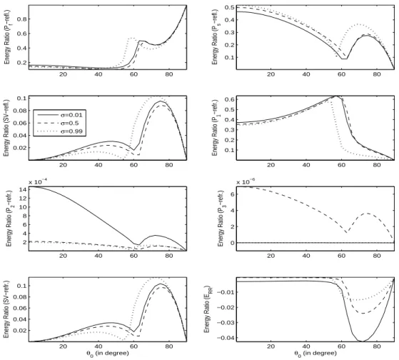
waves interaction energy. Due to the inhomogeneous propagation of refracted waves, a part of the refracted energy share identified as the interaction energy. The variations inenergy partition with incident direction are presented in Fig. 1-3 (for incident
P
f wave), Fig. 4-6(for incident
P
s wave), Fig. 7-9 (for incidentSV
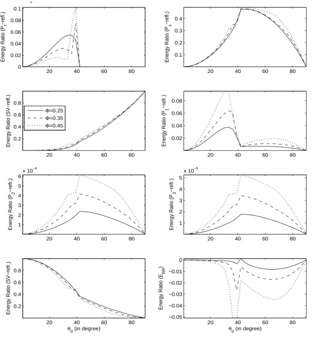
wave) and are discussed as follows.For incident
P
f wave:The variations of energy shares of three reflected
( , , )
P P SV
f s waves, four refracted1 2 3
( , , , )
P P P SV
waves and interaction energy with
0
(0, 90 )
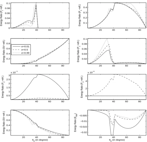
0 are exhibited in Fig. 1, for three/ 2
0.1
kHz
,
0.45
. Near normal incidence, for any
, only reflectedP
s and refractedP
1waves have larger energy shares. On the other hand, at grazing incidence for any
, only thereflected
P
f wave has a significant energy share. A considerable variation in energy shares is visiblewith the change of gas share in pores. It is noted that with the change of gas share in pores the
variation pattern of the energy share of reflected
SV
wave is analogous to the refractedSV
wave.However, the response of reflected
P
f wave to this change is nearly opposite to the reflectedP
swave. A comparison among the energy shares of reflected and refracted waves implies that the
existence propagation of dilatational (i.e.,
P P
2,
3) waves is just namesake. Interaction energy maynot have a physical significance but it ensures conservation of incident energy and certifies, by default, the correctness of whole analytic part of the procedure. The negative (positive) sign of interaction energy implies the travel of energy towards (away from) the interface.
20 40 60 80
0.2 0.4 0.6 0.8
Energy Ratio (P
f
−refl.)
20 40 60 80
0.1 0.2 0.3 0.4 0.5
Energy Ratio (P
s
−refl.)
20 40 60 80
0.02 0.04 0.06 0.08 0.1
Energy Ratio (SV−refl.)
σ=0.01
σ=0.5
σ=0.99
20 40 60 80
0.1 0.2 0.3 0.4 0.5 0.6
Energy Ratio (P
1
−refr.)
20 40 60 80
2 4 6 8 10 12 14
x 10−4
Energy Ratio (P
2
−refr.)
20 40 60 80
0 2 4 6
x 10−6
Energy Ratio (P
3
−refr.)
20 40 60 80
0.02 0.04 0.06 0.08 0.1
Energy Ratio (SV−refr.)
θ
0 (in degree)
20 40 60 80
−0.04 −0.03 −0.02 −0.01
Energy Ratio (E
RR
)
θ
0 (in degree)
Figure 1: Energy shares of reflected (
P P SV
f, ,
s ) waves, refracted( , , , )
P P P SV
1 2 3 and interaction among refracted waves; variations with incident direction (
0)and gas share in pores20 40 60 80 0.2
0.4 0.6 0.8
Energy Ratio (P
f
−refl.)
20 40 60 80
0.1 0.2 0.3 0.4 0.5
Energy Ratio (P
s
−refl.)
20 40 60 80
0.02 0.04 0.06 0.08 0.1
Energy Ratio (SV−refl.)
ω=2π×100Hz
ω=2π×1000Hz
ω=2π×5000Hz
20 40 60 80
0.1 0.2 0.3 0.4 0.5 0.6
Energy Ratio (P
1
−refr.)
20 40 60 80
1 2 3 4
x 10−3
Energy Ratio (P
2
−refr.)
20 40 60 80
2 4 6 8 10
x 10−5
Energy Ratio (P
3
−refr.)
20 40 60 80
0.02 0.04 0.06 0.08 0.1
Energy Ratio (SV−refr.)
θ
0 (in degree)
20 40 60 80
−0.06 −0.04 −0.02
Energy Ratio (E
RR
)
θ
0 (in degree)
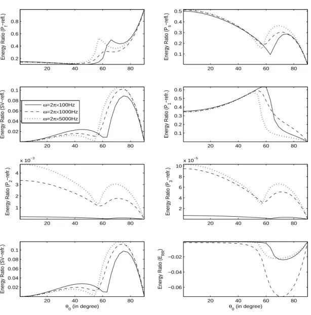
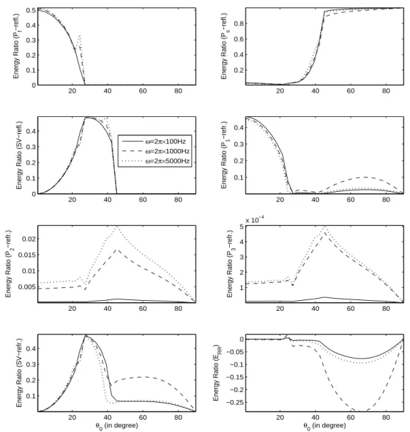
Figure 2: Energy shares of reflected (
P P SV
f, ,
s ) waves, refracted( , , , )
P P P SV
1 2 3 and interactionamong refracted waves; variations with incident direction (
0) and frequency of wave
;K
cap
0.05
K
l,
0.5
,
0.45
; incidentP
f wave.Fig. 2 exhibits the variations of energy shares of three reflected
( , , )
P P SV
f s waves, fourrefracted