Abstract
This paper presents an analytical solution to predict the nonlinear forced vibrations of elastic thin-walled cylindrical shells under suddenly applied loads. Interest in this problem is motivated by effects due to explosions on fluid-storage metal tanks. The model is based on the energy criterion due to Lagrange, in which the kinematic nonlinear relations are assumed using Donnell’s simplified shell theory. Solution is achieved as a series summation in terms of trigonometric functions in the axial and circumferential directions, whereas the degrees of freedom depend on time. A blast load is assumed to represent effects due to explosions on the shell as time-dependent pressures with a given circumferential distribution (a cosine square distribution in terms of the central angle). The procedure is validated by comparison with a nonlinear finite element model under the same load conditions. The influence of load level and shell geometry on the transient response is investigated by mean of parametric studies. Good accuracy is found in the results for the range of shells which are representative of horizontal, fuel storage tanks in the oil industry.
Keywords
Blast loads, cylindrical shells, dynamic buckling, tanks, vibrations.
Simplified Analytical Approach to Evaluate the Nonlinear Dynamics
of Elastic Cylindrical Shells Under Lateral Blast Loads
1 INTRODUCTION
The topics of modeling and understanding the significance of shell vibrations due to blast loads have attracted the attention of researchers for some time. A few classical texts have been published in this field: Lindberg and Florence (1987) reported research concerning uniform radial impulse in elastic as well as plastic material response. Among other significant conclusions, the authors found that under impulsive loads the buckling modes have higher number of circumferential waves than their static counterpart. In Simitses (1990), emphasis is placed on suddenly loaded shells in the axial direction
Mariano P. Ameijeiras a Luis A. Godoy b,*
a Department of Structures, FCEFyN,
Universidad Nacional de Córdoba, Argentina.
b Institute for Advanced Studies in
Engineering and Technology (IDIT UNC-CONICET), and FCEFyN, Universidad Nacional de Córdoba, Argentina.
(*) Corresponding author. E-mail
address: [email protected]
http://dx.doi.org/10.1590/1679-78252587
with infinite duration, rather than on effects due to lateral pulse pressures as in the present case. Amabili (2008) focused on nonlinear vibrations and stability aspects.
Interest in previous studies is mainly motivated by structures of planes, cars, submarines and military applications. But engineering problems for which considerations of blast loads are required are not limited to those areas. A new field of interest involving the nonlinear dynamics of cylindrical shells emerged during the last ten years as a consequence of damage and destruction of oil storage tanks caused by explosions for both, vertical and horizontal tanks. Although most cases of explosions on tanks reported in the literature are caused by accidents, some recent events show that vulnerability with respect to intentional acts should also be of great concern to designers and forensic engineers.
The mechanics of the problem and the variables involved in the phenomenon of an explosion can be seen for instance in Glasstone and Dolan (1977) for nuclear explosions and with more detail in UFC-3-340-02 (2008), with the aim of improving structural designs to resist the effects of explosions.
The spatial distribution of a blast pressure around cylindrical tanks is described in a limited number of publications. In recently reported work, a group of researchers in France performed experiments on small-scale cantilever cylindrical shells having a scale factor of 1:48 to obtain time dependent pressure distributions (Duong et al., 2012a; Duong et al., 2012b; Noret et al., 2012). The goal of such testing program was to establish a probabilistic analysis about threshold values causing different damage levels. Analytical studies based on Donnell’s approximation were performed using static response to establish performance limits based on plasticity. Testing has been recently performed at University of North Carolina at Charlotte by Weggel and Whelan (2013) for small scale rigid models..
An alternative to blast testing is to employ computational Fluid Dynamics or Fluid-Structure interaction to simulate the process, such as in the work of Trajkovski et al. (2014).
The analysis of nonlinear elastic behavior of thin-walled structures subjected to short duration pressures were shown by Ruiz et al. (1989) and Hoo-Fatt and Pothula (2010) for cylindrical shells, Kowal-Michalska et al. (2011) for conical and spherical shells, Gao and Hoo-Fatt (2012) for a cylindrical sector, Goel et al. (2014) for sandwich panels, and Putelat and Triantafyllidis (2014) for ring structures.
Detailed analyses capable of following the nonlinear dynamic response of tanks are restricted to the use of finite element codes, in which realistic pressure distributions and times are currently considered together with strength and different characteristics of shells. However, whenever possible, it is convenient to employ simpler analytical solutions which may serve to estimate the dynamic response of the shell using modest computational resources. This paper focuses on the nonlinear dynamic behavior of horizontal, aboveground tanks subjected to lateral pressures that represent effects due to explosions, in which solution is achieved by means of an analytical representation of the problem.
2 FORMULATION OF NON-LINEAR DYNAMIC PROBLEM
,
s
, , . , . , (1)where is the kinetic energy; is the total potential energy ( ); is the dissipation function; qs are a set of ngc generalized coordinates; and a dot on top of a variable indicates time
derivative.
With reference to Figure 1, the displacement field is given by u(x,θ,t), v(x,θ,t), and w(x,θ,t), the axial, tangential, and out-of-plane components. The kinetic energy, the internal strain energy and the load potential are respectively written as
(2)
/
/ (3)
(4)
(a) (b) Figure 1: Geometry of the shell considered and direction of incident pressure. (a) Side view, and (b) Cross-section.
in which ρ is the density; h is the shell thickness; p is the external pressure; εxx(x,θ,t,z), εθθ(x,θ,t,z),
εxθ(x,θ,t,z) are the time-dependent components of the strain tensor; σxx(x,θ,t,z), σθθ(x,θ,t,z),σxθ (x,
θ,t,z) are the time-dependent components of stress tensor; and px(x, θ,t), py(x, θ,t), pz(x,θ,t) are the
pressure components. In this work we employed the classical Kirchhoff-Love hypotheses, which means that the stresses normal to the middle surface are negligible and strains vary linearly across the thickness. This is a good approximation for thin shells, say R/h>20 (see, for example, Amabili, 2008). Transverse shear strains are retained in Mindlin hypothesis, but those have not been used in this study because of the slenderness of the shells considered.
The dissipative function is assumed in the form
(5)
The elastic constitutive equations are given by
(6) (7)
(8)
Finally, Donnell’s approximation is used to describe the kinematic (strain-displacements) relations in the form
, , , , (9)
, , , , (10)
, , , , (11)
with linear and nonlinear terms in the strains at the mid-surface
(12)
(13)
(14)
The changes in curvature are:
(15)
(16)
(17)
Donnell's equations provide a good approximation in this problem, as will be shown below by means of comparisons with finite element analyses. Use of these equations has been illustrated, for example in the texts by Brush and Almroth (1975) for buckling problems and by Amabili (2008) for vibrations of shells.
Next the displacement field is approximated as a series summation in the general form
, , , , , (19)
, , , , , (20)
The degrees-of-freedom (DOF) of the problem (i.e. the generalized coordinates qs) are ui,j(t), vi,j(t), wi,j(t) where the first subscript refers to summation in the axial direction and the second subscript
refers to summation in the circumferential direction: label 1 refers to cosine circumferential functions, and label 2 refers to sin circumferential functions.
For a load which is symmetric with respect to a plane at θ=0° (as in the present case), the underlined terms of eq.(18) to eq.(20) do not contribute to the solution and the displacements reduce to:
, , , , (21)
, , , , (22)
, , , , (23)
The essential boundary conditions are satisfied at both edges as follows: At x=0
, , (24)
, , (25)
, , (26)
and
, , (27)
at x=L. It may be shown that the following condition is satisfied
, , (28)
The resulting sets of ordinary and algebraic differential equations of motion in terms of time-dependent DOF ui,j(t), vi,j(t), wi,j(t) have been obtained with the help of a symbolic manipulation
software (Mathematica, 2015), and the solution is achieved by use of the IDA code in the SUNDIALS package (2005), which is available in Mathematica.
3 ASSUMED BLAST LOAD
The effect of an explosion as a blast load has been modeled in this work by means of a pressure pattern with assumed time and space variations. As previously mentioned, tests on vertical cylindrical shells under an explosion have been performed in France and in the USA. The results by Weggel and Wheelan (2013) derived a circumferential time-dependent pressure distribution, whereas almost uniform pressures were recorded in elevation. Although testing has been done for vertical cylinders, the pressure patterns can also be used for horizontal tanks, at least for the initial stages after the arrival of the shock wave to the structure.
Because only the shell area most directly exposed to the explosion is affected by pressures, a cosine square function requires a definition in terms of sectors of the shell which are loaded. This does not cause any trouble in a finite element analysis but it becomes cumbersome if analytical expressions are used, as in the present case. A more convenient alternative is using a continuous function to define pressures around the cylinder, similar to what was done in Putelat and Triantafyllidis (2014), i.e.
, , (29)
where p0 is the peak overpressure; t0 is the positive pulse duration; and k1 and k2 are parameters to
adjust the pressure in time and space. Values of k1=1.1, and k2=2.0 where found to closely follow a
cosine square variation.
The applied pressures in space and time are shown in Figure 2 and are compared with values for Cos2(θ) for θ= [π/2, 3/2π]. Excellent agreement is found, with only minor differences in the resulting pressures at the end of the considered interval.
In the present simplified model, all pressures are assumed to act simultaneously around the circumference. This is a simplification in the sense that in real situation there is a time delay between pressures acting at θ=0° and those at other locations of θ. However, results for vertical tanks indicate that such delay has minor quantitative consequences on the dynamics of the shell (Ameijeiras et al., 2014).
(a) (b)
4 VALIDATION OF THE ANALYTICAL MODEL
A specific case has been investigated in detail using the present analytical formulation and results are compared with those obtained from a geometrically non-linear dynamic analysis using finite elements. The shell has a radius R=2.0m, and length between supports L=16.0m, leading to L/R=8 and R/h=200. A constant thickness of the shell h=0.01m is assumed throughout this work. The geometries analyzed in this work are comparable with those of UL-142 (2006) design standard for horizontal tanks. The tank is assumed to be empty and initially at rest and dissipation has been neglected.
The time of the positive phase of the impulse, identified as t0 in Figure 2b, is taken as 0.025s.
The maximum pressure (peak pressure) is p0=200kPa which induces displacements well into the
non-linear kinematic region.
The geometry and load conditions represent a severe case in terms of shell slenderness and transient displacement amplitudes and this stringent condition has been chosen to validate the model.
The transient dynamic response at point A (identified in Figure 3) has been investigated for five discretizations of eq.(21) to eq.(23) involving 24, 48, 60, 72, and 84 DOF with m=p=3 in eq. (18-20). The results are compared with a finite element solution obtained using ABAQUS, with a structured mesh of four-node shell elements with reduced integration (S4R in the ABAQUS nomenclature). Finite element convergence was studied and a mesh of 8904 linear quadrilateral elements was used in this case. The solution of the transient problem was computed with an explicit scheme.
The results are shown in Figure 3 in terms of transient displacements (normalized with respect to the shell thickness) at point A, plotted versus time up to t=10t0. For 24 DOF, the analytical
solution follows the finite element results for a very short time, with a poor approximation obtained at times t>0.02s.
Qualitative improvements are obtained for 48 DOF and 60 DOF, which yield good agreement with finite element results up to t<0.10s, whereas significant improvements are seen to occur for 72 DOF and 84 DOF.
The results indicate displacement levels in the order of 10 times the shell thickness, and even for such high level of non-linearity the analytical solution yields excellent results with a refined 72 or 84 DOF model. The first peak in the time-dependent displacements is also the highest one, reaching values in excess of ten times the shell thickness h. This peak occurs after the positive phase duration t0, in which case the positive pressures cease to act. The next peak occurs at t=3t0, with a displacement
higher than 6h. A high peak in displacements is also found at t=7t0, on account that damping has
not been included in this analysis.
(a) (b)
(c) (d)
(e)
Figure 3: Transient displacements at point A, for p0=-200kPa, t0=0.025s, L/R=8, R/h=200: (a) 24 DOF, (b) 48 DOF, (c) 60 DOF, (d) 72 DOF, and (e) 84 DOF.
This is very stringent case, because the pressure level is very high and the geometry of the shell (with L/R=8 and R/h=200) makes it a slender case in which large displacements take place. But even for these extreme conditions it may be seen that the present simplified nonlinear dynamic solution provides excellent results with respect to similar studies using a more powerful finite element analysis.
(s) (s)
(s) (s)
(a) (b)
Figure 4: Deflection modes obtained from present analytical solution, with 72 DOF. (a) 3D view, and (b) 2D view at x=L/2, for p0=-200kPa, t0=0.025s, L/R=8, R/h=200, at t=0.035. Scale factor for displacements=10.
(a) (b)
Figure 5: Finite element results for the same data as in Figure 4,(a) 3D view, and (b) 2D view at x=L/2. Scale factor for displacements=10.
Figure 6: Transient velocity , at point A, for p0=-200kPa, t0=0.025s, L/R=8, R/h=200.
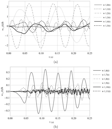
Finally the contribution of each harmonic in the displacement field has been investigated in Figure 7, for a 72 DOF model. From the plots, it seems that the main contributions are given by modes 1 to mode 5. Mode 0 (the breathing mode) and modes higher than 6 do not have a significant contribution to the solution.
(a)
(b)
Figure 7: Displacements w1j(t) for a shell with L/R=8, R/h=500 and computed for 72 DOF. (a) Contribution of modes 0 to 5; and (b) Contribution of modes 6 to 11.
(s)
(m/s)
Based on the above studies, a solution with 72 DOF was chosen to perform further studies and results that follow are shown for such discretization of the analytical solution.
5 INFLUENCE OF THE LOAD LEVEL
In the case employed for validation of results in the previous section, a single peak pressure value was used, and the incidence of the peak pressure level is studied in this section. The geometry of the shell for this study is such that L/R=4 and R/h=250 to better represent geometries of horizontal tanks.
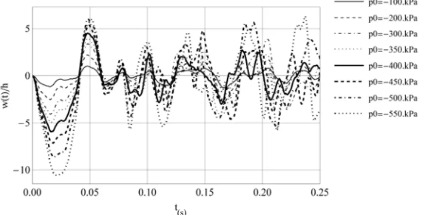
The normalized out-of-plane displacement at point A has been computed for peak pressures in the range 100kPa≥p0≥550kPa, and results are plotted in Figure 8. The first peak displacement occurs
before 2t0. The displacements have a nonlinear relation with loads: The peak pressures have been
increased by a factor of 5.5; however, the increase in displacements can be tenfold.
Figure 8: Transient displacement at point A for several increasing peak pressures, for L/R=4, R/h=250.
The maximum displacements have been plotted in as function of pressure level. This graph has been identified as a pseudo-equilibrium path, by analogy with the static nonlinear behavior (Virella et al., 2006). To facilitate understanding of the results, the pressures have been normalized with respect to the classical critical static (LBA) pressure pc for the same pressure distribution as given by
eq.(29); this critical value has been computed using ABAQUS as pc=70.4kPa.
A pseudo-equilibrium path is suitable to investigate the occurrence of dynamic buckling along the path of transient displacements, at least for some time-dependent loads. According to the dynamic buckling criterion due to Budiansky and Roth (1967), a sharp change in this plot (Figure 9a) is expected to occur when the shell undergoes dynamic buckling, with a small increase in load causing a large increment in displacements. In the present case, the plot shows a non-linear relation between load and displacement, but this is a gradually softening relation without any sharp changes. This indicates that dynamic buckling is not expected to occur along this path according to the Budiansky and Roth criterion.
For short impulsive loads, such as those happening during seismic motions, a variant has been proposed in which the slope dp/dw is followed to identify a change in the stiffness of the shell (Virella et al., 2006). Results are plotted in Figure 9b; however, no sudden change is identified even for very high peak pressures p=500kPa.
(a) (b)
Figure 9: Pseudo-equilibrium path for t0=0.025s, L/R=4, R/h=250. (a) Maximum displacement at A as a function of peak pressures,
(b) Slope of pseudo-equilibrium path.
The existence of an instability can also be studied in a phase-space diagram. Plots are shown in Figure 10 for the range of p0 under study. Again, it may be seen that the solution remains bounded
and a divergence-type instability does not occur.
(a) (b)
(c) (d)
Figure 10: Phase plane computed at point A, for: (a) p0=100kPa, (b) p0=300kPa, (c) p0=450kPa, and (d) p0=550kPa for t0=0.025s, L/R=4, R/h=250.
(m/s)
(m/s)
(m) (m)
(m/s) (m/s)
(m) (m)
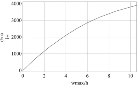
Finally, the unit impulse of the positive phase (shown in Figure 2b) at θ=0 has been computed as
e (30)
For such a high level of suddenly applied load, Figure 11 shows a plot of impulse of the positive phase peak displacement. This seems to be a better description of the phenomenon under a blast load which is dependent on the impulse rather than on the value of pressure itself (Lindberg and Florence, 1987, Ameijeiras and Godoy, 2013).
Figure 11: Maximum displacement at A as a function of peak impulses, for t0=0.025s, L/R=4, R/h=250.
6 INFLUENCE OF THE SHELL GEOMETRY
The main geometric parameters governing the shell response are the R/h and L/R ratios, and those are investigated in this section.
6.1 Influence of R/h Ratio
The non-linear dynamic response of the cylindrical shell has been studied for a range of slenderness 50≤R/h≤250, for a fixed aspect ratio L/R=4, and for a given pressure p0=500kPa.
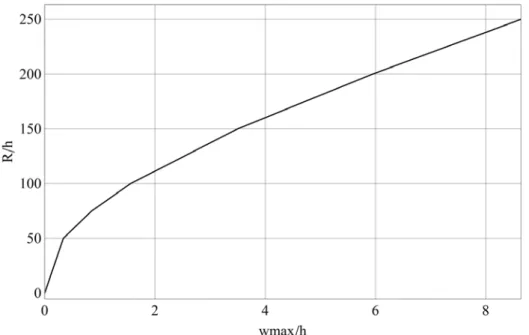
Results for the transient response at point A (identified in Figure 1) are shown in Figure 12. The peak displacements are normalized each with respect to their respective thickness h. In this nonlinear problem, as the ratio R/h increases towards a more slender shell, the maximum displacements also increase.
A summary of results for normalized maximum displacement is shown in Figure 13, in which a non-linear relation is seen to occur with respect to R/h. The plot of Figure 13 shows a sharp change in slope between R/h=50 and R/h=100, after which the slope of the curve becomes less pronounced. There seems to be a transition between shells of moderate slenderness (R/h<100) to slender shells
Figure 12: Transient displacements at A for several R/h ratios, for p0=500kPa, t0=0.025s, L/R=4.
Figure 13: Maximum displacement at A as a function of R/h ratio, for p0=500kPa, t0 =0.025s, L/R=4.
6.2 Influence of L/R Ratio
For a slenderness R/h=250 and peak pressure p0=125kPa, results have been computed for aspect
ratios in the range 1≤L/R≤10. Results are shown in Figure 14 and a summary of normalized peak displacements versus L/R is shown in Figure 15. Again, a change in slope is seen to occur in Figure 15 in the range L/R=2 to L/R=4, with an almost linear trend for higher L/R ratios.
Figure 14: Transient displacements at A for several L/R ratios, for p0=125kPa, t0=0.025s, R/h=250.
Figure 15: Maximum transient displacement at A as a function of L/R ratio, for p0=125kPa, t0=0.025s, R/h=250.
7 CONCLUSIONS
A simplified analytical procedure, based on Lagrange energy criterion and Donnell shell equations, was presented in this work to analyze the nonlinear elastic response of cylindrical shells under blast loads due to explosions. The formulation has been validated with respect to a geometrically nonlinear finite element analysis for a specific shell configuration. The formulation allows identification of the contribution of each mode included in the analysis.
The shell dimensions are representative of horizontal tank configurations, as employed in the chemical and oil industries to store fluids. Horizontal tanks are frequently supported on saddles at the ends, which provide support on a central angle of approximately 90º. Simplified models, on the other hand, assume that there is a condition at the ends which provide support around the complete
the structural response. Vertical tanks with fixed roof or wind girder at the top are also considered as simply supported shells at both ends. Recent studies on effects due to such simplifications (Burgos et al. 2015) illustrate that this is a reasonable approximation under lateral loads (such as in the present study) and induces errors only under thermal loads.
The main conclusions of the study can be summarized as follows:
1.The present analytical solution yields accurate transient results even for cases in which shell and load characteristics induce highly nonlinear displacements.
2.A very low number of circumferential DOF are needed to correctly model the phenomenon and an even lower number of longitudinal DOF. For the cases considered, the use of 72 DOF produces good results at least up to relations of R/h=250 and for all range of R/L ratios covered in this study, which are necessary to predict the non-linear behavior of most horizontal storage tanks.
3.In a pseudo-equilibrium path (i.e. load versus maximum displacement), the effect of nonlinearity may be seen as a softening process, i.e. for a given load level, the displacement are larger than those that would be given by a linear model.
4.There is a significant influence of the R/h ratio on the maximum transient displacements, at least for shells with R/h>80.
5.A similar influence occurs for shells as a function of L/R ratio: significant nonlinearity occurs for L/R>3.
A complete study of dynamic buckling has not been attempted in this work, but the results indicate that the response is stable along the transient displacement path, according to the criterion due to Budiansky and Roth. Bifurcations from this transient path, such as those investigated in Kleiber et al. (1987), have not been addressed in this work and are seen as an important topic for further research.
The influence of plasticity has not been considered in this simplified solution, but the results for these very thin shells indicate that vibrations remain within the elastic regime.
Acknowledgments
The authors thank the support received from grants of the National University of Córdoba and of the Science and Technology Research Council of Argentina, CONICET (PIP 0126). LAG is a member of the Research Staff of CONICET (Investigador Superior).
References
Abaqus (2009). Simulia. Dassault Systemes. Warwick, RI.
Amabili M. (2008). Non-linear vibrations and stability of shells and plates. Cambridge University Press, New York, NY.
Ameijeiras M.P., Godoy L.A. (2013). Respuesta no lineal de tanques de almacenamiento de petróleo frente a cargas debidas a explosiones. Mecánica Computacional 32:3323-3340 (in Spanish).
Ameijeiras M.P., Godoy L.A., Weggel D., Wheelan, M. (2014). Incidencia del tiempo de arribo de onda en la respuesta de tanques sometidos a explosiones externas. Mecánica Computacional 33:931-942 (in Spanish).
Budiansky B. (1967). Dynamic buckling of elastic structures: Criteria and Estimates, in: Dynamic Stability of Structures 83-106, Ed. G. Herrmann, Pergamon Press, Oxford, UK.
Burgos C. A., Batista-Abreu J. C., Calabró H. D., Jaca R. C., Godoy L. A. (2015), Buckling estimates for oil storage tanks: Effect of simplified modeling of the roof and wind girder, Thin-Walled Structures 91: 29-37.
Donnell, L.H. (1976). Beams, Plates and Shells. Mc Graw-Hill, New York, NY.
Duong, D.H., Hanus, J.L., Bouazaoui, L., Pennetier, O., Moriceau, J., Prod’homme G., Reimeringer, M. (2012). Response of a tank under blast loading – Part I: Experimental characterization. European Journal of Environmental and Civil Engineering 16(9):1023-1041.
Duong, D.H., Hanus, J.L., Bouazoui, L., Regal, X., Prod’homme, G., Noret, E., Yalamas, T., Reimeringer, M., Bailly, P., Pennetier, O. (2012). Response of a tank under blast loading – Part II: Experimental structural response and simplified analytical approach. European Journal of Environmental and Civil Engineering 16(9):1042-1057.
Gao, Y., Hoo Fatt, M. S. (2012). Dynamic pulse buckling of single curvature composite shells under external blast. Thin-Walled Structures 52:149-157.
Géradin, M., Rixen, D.J. (2015). Mechanical Vibrations-Theory and Application to Structural Dynamics, 3rd. Edition. John Wiley & Sons, London, UK.
Glasstone S., Dolan P.J. (1977). The effects of nuclear weapons, 3rd. Edition. The United States Department of Energy, Washington, DC.
Goel M. D., Matsagar V. A., Gupta A. K. (2014), Blast Resistance of Stiffened Sandwich Panels with Closed-Cell Aluminum Foam, Latin American Journal of Solids and Structures 11(13): 2497-2515.
Hindmarsh, A.C., Brown, P.N., Grant, K.E., Lee, S.L., Serban, R., Shumaker, D.E., Woodward, C.S. (2005). SUNDIALS: Suite of Nonlinear and Differential/Algebraic Equation Solvers. ACM Transactions on Mathematical Software 31(3):363-396.
Hoo-Fatt, M.S., Pothula, S.G. (2010). Dynamic pulse buckling of composite shells subjected to external blast. Composite Structures 92:1716-1727.
Kleiber, M., Kotula, W., Saran, M. (1987). Numerical analysis of dynamic quasi-bifurcation. Engineering Computations 4: 48-52.
Kowal-Michalska, K., Kubiak, T., Swiniarski, J. (2011). Influence of blast pressure modeling on the dynamic response of conical and hemispherical shells. Thin-Walled Structures 49:604-610.
Lindberg H. E., Florence A. L. (1987). Dynamic Pulse Buckling. Martinus Nijhoff, Dordrecht, Netherlands. Mathematica (2015), Mathematica, Wolfram Research, Champaign, IL.
Noret, E., Prod’homme, G., Yalamas, T., Reimeringer, M., Hanus, J.L., Duong, D.H. (2012). Safety of atmospheric storage tanks during accidental explosions. European Journal of Environmental and Civil Engineering 16(9):998–1022. Putelat, T., Triantafyllidis, N. (2014). Dynamic stability of externally pressurized elastic rings subjected to high rates of loading. International Journal of Solids and Structures 51:1-12.
Ruiz, C., Salvatorelli, F., Thompson, V.K. (1989). Elastic response of thin-walled cylindrical vessels to blast loading. Computers and Structures 32(5):1061-1072.
Simitses, G. (1990). Dynamic Stability of Suddenly Loaded Structures. Springer-Verlag, New York, NY.
Trajkovski J., Kunc R., Perenda J., Prebil I. (2014), Minimum mesh design criteria for blast wave development and structural response – MMALE method, Latin American Journal of Solids and Structures 11(11): 1999-2017.
UFC 3-340-02 (2008). Structures to resist the effects of accidental explosions. Unified Facilities Criteria, US Department of Defense, Washington, DC.
Virella, J.C., Godoy, L.A., Suárez, L.E. (2006). Dynamic buckling of anchored steel tanks subjected to horizontal earthquake excitation. Journal of Constructional Steel Research 62(6):521-531.