*e-mail: [email protected]
Introduction
The research in sensors applications shows an extensive application and has increased over the past decade 1. The need
to identify and quantify small amounts of speciic species
has also contributed to the arousing interest in sensors and biosensors 2 owing to many biological and chemical processes depends on pH and it could aid in pH measurement, for example.
Bergveld used a ield effect transistor to measure pH in neurophysiological conditions for the irst time in 1970 3.
The ion-sensitive ield effect transistor (ISFET) is an
integrated device consisting of a metal-oxide-semiconductor
ield-effect-transistor (MOSFET) in which a sensing electrode
replaces the gate 4. This device has been developed to operate as a chemically selective electrode 5. Compared with conventional pH-sensitive glass electrodes, the chemical sensor offers numerous advantages such as low cost, the possibility of miniaturization, and high input and low output impedance 6. These devices are very versatile and their use has even been recently reported as wireless gastrointestinal sensor 4,7. However, ISFET is a device that does not allow the sensitive membrane changes. Bearing research and future technological applications in mind, a good strategy would be
to replace ISFET with the extended-gate ield-effect-transistor (EGFET), due to its possibility to isolate the sensitive layer from the electronic components. In EGFET, a conducting wire connects a commercial MOSFET to a sensitive layer
8 , and it is easy to replace the sensitive layer. Moreover, it is feasible to alter the measurement conditions without
modifying the MOSFET conditions, as the light exposure
of the extended gate and the temperature of the sensing
ilm as well.
EGFET can be used as a pH sensor to detect and quantify
a big kind of substances that can produce or consume protons,
such as enzymes, which could open up a wide range of
EGFET applications as biosensors 9. Researchers have tested and characterized a number of materials to use as ion-sensing
ilm in EGFETs; for example, zinc oxide (ZnO) 10, tin oxide
(SnO2)
11, titanium oxide (TiO 2)
12, luorine-doped tin oxide
(SnO2:F)
13 , tantalum pentoxide (Ta 2O5)
14, and mixed oxides like vanadium oxide/hexadecylamine 15, and pentoxide vanadium/ titanium oxide (V2O5/TiO2) 16, among others.
Tin oxide (SnO2) is one of the most important transparent conductive oxide (TCO) materials 17. It exhibits high electrical conductivity and optical transmittance in the UV-vis region 18, can resist to high temperatures 19, and presents high IR
relectance 17. Doping helps to reine SnO
2 for TCO applications
and the dopants can be luorine 20, antimony 21, indium 22, and zinc 17. Previous studies have reported that luorine and
antimony are better dopants for SnO2 ilms, because they elicit low electrical resistivity and high transmittance for solar cell applications 17,23. The formation of F-Sn complexes reduces both the concentration and mobility of the carriers 18, and the dopant considerably affects the reaction process
by controlling the SnO2 ilm growth kinetics 24. SnO
2:F
(luorine doped tin oxide) ilms are thermally stable, do not
depend on oxygen vacancies to provide charge carriers 25, resist physical abrasion, and display chemical stability, high optical visible transparency, and electrical conductivity 26.
SnO2:F is an alternative to indium-doped tin oxide (ITO) when chemical or electrical stability is necessary at elevated temperatures 27. SnO
2:F has application in many optoelectronic devices such as the electrodes employed in various types of solar cells 28,29.
The transient effects of sensors, including ISFETs and EGFETs, and the speciic and detailed conditions of devices
operation and characterization have been explored less than
necessary. Batista et al. grew SnO2:F by the sol-gel technique
Effects of Measurements Conditions on an Extended-Gate FET used as pH sensor
Jessica Colnaghi Fernandesa*, Raphael Aparecido Sanches Nascimentoa, Marcelo Mulatoa
aPhysics Department, University of São Paulo – USP, Av. Bandeirantes, 3900, Ribeirão Preto, SP, Brazil
Received: May 4, 2015; Revised: November 3, 2015; Accepted: December 16, 2015
Fluorine-doped tin oxide (SnO2:F) was investigate as the sensitive part of a pH sensor in the
extended-gate ield effect transistors (EGFET) device, which provided a linear response for pH range
from 2 to 12; the sensitivity was 37 mV.pH-1 for experiments performed in absence of light. Neutral pH, leads to a transistor’s electric current remained practically constant, suggesting that pH 7 correspond
to the isoelectric point of the SnO2:F samples. For acid and alkaline pH, the power law varied along time and stabilized at about 10 min. UV-vis light did not alter the results. The transistor’s electric current increased with the operating temperature increases. Once that small change in the operating
conditions can alter the inal results, the physical mechanisms underlying the sensing process must
be clearly understood. It is essential to monitor transient response and measurements conditions.
and used it in EGFET to obtain a good response as a function
of pH and high sensitivity 13. However, it is essential to conduct a more detailed study of the transient behavior of the sensor containing this material. The present study used
SnO2:F ilms and focused on the transient and operating temperature effects. Measurements with time-evolved
results for the SnO2:F sensing ilm in a pH sensor EGFET device as a function of time, illumination, and operating temperature are discussed.
Materials and Methods
The SnO2:F samples were purchased from Flexitec company. The company fabricated those samples via the spray-pyrolysis technique and they present 512 nm thickness
in average, 10 mm x 23 mm surface area, and 23 Ω/sqr sheet resistance. Electric contact was made using a thin
copper wire and conductive silver paint on the edge of the sample. The contact was encapsulated with an epoxy resin. Previous studies had reported that silver paint forms ohmic
contacts with SnO2:F and displays low resistivity, because
silver diffuses in the ilm and increases the number of free
charge carriers as compared with other metallic contacts 30.
The EGFETs were fabricated by connecting the samples to the gate of a commercial MOSFET (CD4007) - Texas
Instruments. The samples were dipped in buffer solutions with
pH values ranging from 2 to 12, acquired from CINETICA.
1. EXPERIMENTAL
The samples were rinsed with Milli-DI water for 15 min before each measurement. Milli-DI contains only a small amount of ions. Normally its conductivity lies between
1 and 0.1 µS•cm1, so its resistivity is around 1 to 10 MΩ•cm.
The amount of ions that might remain on the ilm´s surface
after each cleaning process is much smaller than the amount of ions originated from the buffer solution. Hence, the standardized cleaning process ensures that the charge and
the inal measurements varies only due to the buffer solution ions interaction with the surface of the ilm. The minimum
amount of ions in the Milli-DI water does not affect the
inal result.
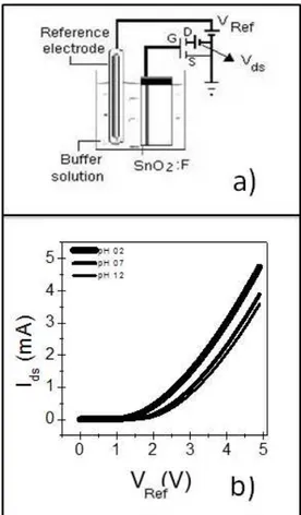
Figure 1(a) illustrates the experimental setup. A reference
silver electrode was connected to the drain of the MOSFET, while its source terminal is grounded. According to the igure,
VRef corresponds to the reference electrode voltage, Vds is the voltage between the drain and the source, and Vgs is the voltage between the gate and the source. In fact, Vgs consist of VRef plus the voltage built up between the solution and
the ilm (dV). The drain-source current (Ids) was measured using an HP Data Acquisition 34970A system. An Agilent
E3646A Dual Output DC Power Supply unit was also
employed in the set-up.
The measurements were conducted both in the absence
of light and under UV-VIS radiation.
For this, a system with 14 ultra bright white LEDs (diameter of 5 mm) was connected to a DC FA-3005 Power Supply. The LEDs were operated at 6 V (20 mA), at a total distance of about 22 cm from the ilms, with irradiance of
6.7 Wb.m-2 over the sample. The entire apparatus shown in Figure 1(a) was kept inside a dark box together with the
LEDs system. For experiments in presence of light the LEDs
were turned on, and for experiments in the dark the LEDs
were kept switched off.
For the experiments as a function of operating temperature,
a thermostat was kept inside the buffer solution with the
sensing ilm and the reference electrode. The complete
apparatus (the same shown in Figure 1(a)) was partially immersed in a beaker with water and a magnetic stirrer. Data were only acquired after the temperature of the buffer solution was stabilized. All measurements were performed inside the control box.
Figure 1(b) shows typical Ids x VREF curves. Measurements were accomplished by varying the gate-source voltage while keeping Vds ixed. The sensitivity of the device is determined
by using ixed Ids values
31,32. This measurement was referred to as the Vgs setup.
This kind of device can lead to many possible sensor
conigurations and operation conditions, because Ids depends on the pH of the buffer solution (Figure 1(b)). The response of the devices were investigated using time evolution, light absence or its presence and as a function of the operating temperature.
This paper proposes the standardization of the results to facilitate the experiments reproduction and thereby increases the success of new sensors production. Unfortunately, there is no results in literature to compare with the data acquired in this paper.
Results and Discussion
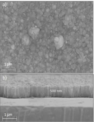
Figure 2 shows the scanning electron microscopy (SEM) image of an original SnO2:F sample. Figure 2(a) shows that the surface is very rough and porous, with submicrometric grains, leading to a total exposed surface area greater than the conventional geometric area. Figure 2(b) shows that
the SnO2:F sample is about 500 nm thick, and that the submicrometric grains have a columnar structure.
Figure 3 shows the Ids time evolution for different buffer solutions, measured in the absence of light. Both Vds and VRef were kept constant. The current depends on the buffer solution pH. Increasing pH (i.e., lower H+ concentration in the solution) elicits smaller currents. Water molecules in the solution attach to the sample surface, generating free sites to which H+ ions can bind. This will generate H
3O
+ ions and the typical double layer of the Helmholtz plane 33, followed by
the Gouy-Chapman region, where charge diffusion extends
to the solution bulk. These two regions determine or even modulate the potential gradient across the solution, leading to varied currents. The higher the amount of H+ ions in the
solution the thicker the Gouy-Chapman region, and the faster the Gouy-Chapman region is formed, leading to larger current
values. The focus was on the surface/electrolyte interface 34. The time evolution of the electric current heavily depends on pH values and presents distinct behavior in acid, neutral, and alkaline solutions. The isoelectric point, or point of
zero charge (PZC), is the point where the electrical charge
density on a surface is zero. Depending on the electrolyte pH,
the SnO2:F surface can be neutral, positively or negatively charged 35-37.
The surface potential (ψ) between the sensitive layer and the electrolyte interface depends on the PZC according
to the site-binding model 38:
(
)
2.303 1 kT
PZC pH
q
β ψ
β
= −
+ (1)
T is the absolute temperature, k is the Boltzmann constant,
q is the electron charge, and β is the sensitivity factor. When the pH of the solution is lower than the PZC, the hydroxide species on the surface of the ilm are mostly
protonated, to give –OH2+. This elicits a positive net charge on the surface 39,40.
The acid buffer solutions with pH 2, 4, and 6 shift the reaction equilibrium toward hydronium ions formation, so
the surface of the ilm becomes positively charged. Further
stabilization follows a power law decay (Figure 3(a)).
The most marked reduction occurs within the irst minute. As the free sites on the surface of the ilm acquired a positive
charge due to the presence of hydronium ions from the
solution, the double layer and the Gouy-Chapman region
arise rapidly, and the current decreases until stabilization. The same behavior applies to other acid pH values, like pH 4 and 6 (not shown in Fig. 3), but increasing pH values culminate in smaller amplitudes.
At pH 7, the current varies little with time (see Figure 3(b)), suggesting that this pH corresponds to the isoelectric point
of the SnO2:F samples.
When the solution pH is larger than the PZC, most of the hydroxide species on the ilm surface will be deprotonated,
to form –O-, providing a negatively charged surface 40,41. The power law rises (Figure 3(c)). The time constant for
Fig. 2. Scanning electron microscopy (SEM) studies of the starting
SnO2:F sensing ilm: (a) Surface and (b) tilted cross section.
alkaline solutions is much larger as compared with that of acid solutions. The same behavior holds for other alkaline
pH values, such as pH 8 and 10 (not shown in the igure).
The buffer solutions with pH 8, 10, and 12 shift the process equilibrium toward the formation of negative ions,
so the surface of the ilm is negatively charged. A solution
with alkaline pH does not rely on a large supply of H+ ions;
hence the double layer and the Gouy-Chapman region
take longer to form as compared with the situation in acid pH. This results from the lower mobility of negative ions in relation to hydronium and from a smaller availability of positive species. Double-layer generation depends on complex ion interactions, charge movement (such as the competition between ion diffusion and drift), changes in the
electric ield inside the solution, and chemical equilibrium
in the buffer solutions 42. Together, these facts account for
the current temporal evolution proile.
To better visualize the total current variation for each
pH along 10 min, the absolute value of the difference (ΔIds) between the initial (Ids0) and the inal (Ids600) currents from
Figure 3 were divided by the respective initial values.
The new ΔIds/Ids0 variable was plotted as a function of pH in
Figure 4. The solid squares in the igure correspond to the
experiments performed in the absence of light.
According to the data in Figure 4, the total current varies slightly less for acid solutions as compared to alkaline solutions, as discussed in Figure 3. The maximum current variation for each pH value corresponds to less than 5%. The total current variation (considering the initial values only) between pH 2 and 12 is about 30%. In other words, the current variation along time is smaller than the maximum interval of initial currents between pHs 2 and 12. Figure 4 shows that the current does not vary at pH 7. As previously discussed, this might correspond to the isoelectric point of
the SnO2:F ilm, where no variation should occurs. Data from experiments involving sample irradiated with UV-vis light during the measurement were also collected.
Figure 4 shows the results in the presence of light as open circles. A previous study showed that exposure to light
could affect EGFET sensitivity 42.In this work, the data
do not vary signiicantly as compared with the previous
case; i.e., less than 0.5%. The sensitivities are close too, indicating no effect from light. Note that the sensitivity obtained for the experiments accomplished in the absence of light was 37 mV.pH-1. The estimated uncertainty is about 10%. The samples assayed in the presence of light display sensitivity of 34 mV.pH-1. Both results do not reach the highest possible theoretical sensitivity of 59.2 mV.pH-1 predicted by the Nernstian law 43. Nevertheless, we believe that this fact
does not jeopardize the actual indings.
Many authors have reported on new sensor properties, but few have provided information about current evolution along time. This prevents the comparison between independent research works, and future applications might not be directly
practicable. Either instantaneous or stabilized situation during sensor´s operation might be used, but the speciic
condition must be clearly stated. In addition, conducting measurements in the presence or absence of light might
impact the inal results, even though the present data do not differ signiicantly.
Another important parameter to be investigated is the operating temperature, considering both the solution and
the sensing part of the EGFET at thermal equilibrium.
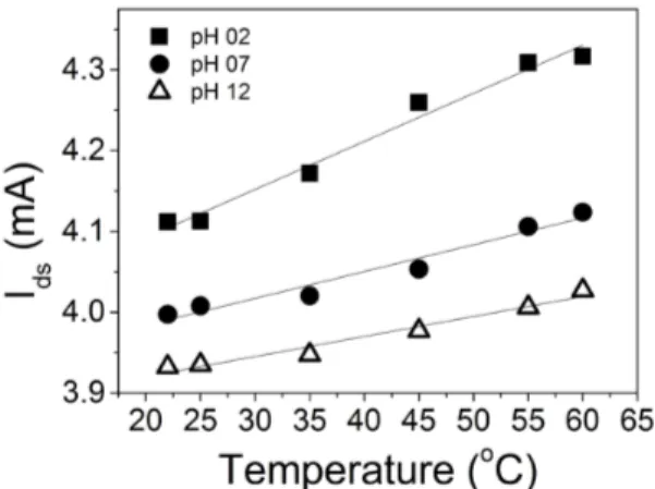
Resistivity is a temperature-dependent variable: higher solution temperatures should reduce the resistivity of the semiconducting material. Figure 5 presents the relevant results for three pH values (2, 7, and 12). The operating temperature used for these buffer solutions varied from 25 to 60o C, in steps of 5o C. The current rises with temperature increases in all cases.
Both ion mobility in the solution and ion adsorption at
the SnO2:F ilm surface depend on the temperature of the system 44. Ion mobility should be a function of increasing temperature in the studied temperature range. On the other
hand, adsorption onto the ilm surface usually decreases with temperature. For the Vgs setup, changes in the MOSFET
inal current originate mainly from dV variation (that builds
up above VREF to compose the inal Vgs). The Ids0 values in
Figure 5 are extracted from the original data (as plotted in
Figure 1(b)) when Vds and VREF are both ixed at 5 V; i.e., the
system variation is associated with the inal dV. The maximum
current variation is about 5%. Normally, increasing electric
Fig. 5. Drain-source current as a function of operating temperature for three different pHs 2, 7 and 12.
ields and higher temperatures enhance mobility, causing larger charge separation in the system. Higher electric ields arise between the reference electrode and the sensing ilm,
which culminates in larger dV values. Indeed, the slopes in
Figure 5 are pronounced, especially for lower pH, probably because the availability and mobility of the positive (lighter) and negative (heavier) species inside the solution varies. The possible reduction in ion adsorption does not seem to
play a signiicant role in this temperature range, since the
sensitivity increased 60% at the highest temperature. Hence, it is very important to describe the solution temperature when comparing different sensors in the literature. This is important
not only for characterization but also for the eventual inal
technological application of the device.
Conclusions
The Ids time evolution depends on the solution pH value.
For acid pH, stabilization follows a power law decay. In the
case of alkaline pH, saturation follows a power law rise. The current varies by a total of almost 30% from pH 2 to 12, but maximum current variation as a function of time is less than 5% at a certain pH value. The percentage of current
variation changes with the pH value. UV-vis irradiation does
not signiicantly alter the inal response as compared with
experiments performed in the absence of light. The operating
temperature alters the device response. For acid pH, the
current value increases more markedly with temperature as compared with alkaline and neutral media. Ion mobility plays a more crucial role than ion adsorption at temperatures below 60o C. The sensitivity increases about 60% when the operating temperature was about 60o C. In summary, for
SnO2:F EGFETs, both the time elapsed during the measurement and the operating temperature can substantially modify the system’s response. This study reinforces the importance of monitoring transient responses and of always describing the measurement conditions in novel studies that develop sensors and biosensors. The contribution is propose the results standardization, with more details, due to small operating changes can lead to different conclusions, as showed. With that, new sensors and biosensors can be developed.
ACKNOWLEDGMENT
The study was supported by FAPESP, CAPES, and
CNPq Brazilian agencies.
References
1. Kao CH, Chen H, Kuo LT, Wang JC, Chen YT, Chu YC, et al. Multi-analyte biosensors on a CF4 plasma treated
Nb2O5-based membrane with an extended gate field effect transistor structure. Sensors and Actuators B: Chemical. 2014;194:419426. doi:10.1016/j.snb.2013.12.056
2. Thevenot DR, Toth K, Durst RA, Wilson GS. Electrochemical
biosensors: recommended definitions and classifications. Biosens Bioelectron. 2001;16(1-2):121131.
3. Bergveld P. Development of an ions-sensitive solid-state device for neurophysiologica measurements. IEEE Transactions on Biomedical Enginering. 1970;17(1):70-71. DOI: 10.1109/
TBME.1970.4502688
4. Xu F, Yan G, Wang Z, Jian P. Continuous accurate pH measurements of human GI tract using a digital pH-ISFET
sensor inside a wireless capsule. Measurement. 2015;64:49-56. doi:10.1016/j.measurement.2014.12.044
5. Yin L-T, Chou J-C, Chung W-Y, Sun T-P, Hsiung S-K. Study
of indium tin oxide thin film for separative extended gate
ISFET. Materials Chemistry and Physics. 2001;70(1): 12-16.
doi:10.1016/S0254-0584(00)00373-4
6. Sasaki Y, Kawarada H. Low drift and small hysteresis characteristics of diamond electrolyte-solution-gate FET. Journal of Physics D: Applied Physics. 2010;43(37): 374020.
7. Xu F, Yan G, Zhao K, Lu L, Gao J, Liu G. A wireless capsule system with ASIC for monitoring the physiological signals
of the human gastrointestinal tract. IEEE Transactions on Biomedical Circuits Systems. 2014;8(6):871-80. doi: 10.1109/
TBCAS.2013.2296933
8. Batista PD, Mulato M, Graeff CF, Fernandez FJ, Marques FC. SnO2 extended gate field-effect transistor as pH sensor.
Brazilian Journal of Physics. 2006;36(2A):478-482. http://
dx.doi.org/10.1590/S0103-97332006000300066
9. Turek M, Keusgen M, Poghossian A, Mulchandani A, Wang J, Schoning M. Enzymemodified electrolyte-insulator-semiconductor
sensors. Journal of Contemporary Physics. 2008;43(2):82-85.
10. Batista PD, Mulato M. ZnO extended-gate field-effect transistors
as pH sensors. Applied Physics Letters. 2005;87:143508. http:// dx.doi.org/10.1063/1.2084319
11. Chou J C, Wang YF. Preparation and study on the drift and hysteresis properties of the tin oxide gate ISFET by the sol-gel
method. Sensors and Actuatros B: Chemical. 2002;86(1):58-62.
DOI: http://dx.doi.org/10.1016/S0925-4005(02)00147-8 12. Zhao R, Xu M, Wang J, Chen G. A pH sensor based on the TiO2
nanotube array modified Ti electrode. Electrochimica Acta.
2010;55:5647-5651. DOI: 10.1016/j.electacta.2010.04.102
13. Batista PD, Mulato M. Polycrystalline fluorine-doped tin
oxide as sensoring thin film in EGFET pH sensor. Journal of Materials Science. 2010;45:5478-4571.
14. Matsuo T, Esashi M. Methods of ISFET fabrication. Sensors and Actuators. 1981;1:7796. doi:10.1016/0250-6874(81)80006-6
15. Guerra EM, Ciuffi KJ, Oliveira HP. V2O5 xerogel-poly(ethylene
oxide) hybrid material: synthesis, characterization, and electrochemical properties. Journal of Solid State Chemistry. 2006;179(12):3814-3823. doi:10.1016/j.jssc.2006.08.018
16. Guerra EM, Silva GR, Mulato M. Extended gate field effect
transistor using V2O5 xerogel sensing membrane by sol-gel method. Solid State Science. 2009;11:456-460. DOI: 10.1016/j. solidstatesciences.2008.07.014
17. Vijayalaksmi S, Venkataraj S, Subramanian M, Jayavel R.
Physical properties of zinc doped tin oxide films prepared by spray pyrolysis technique. Journal of Physcis D: Applied Physics. 2008;41(3):3550.
18. Martínez AI, Huerta L, Rueda de LeónJM, Acosta D, Malik
O, Aguilar M. Physicochemical characteristics of fluorine doped tin oxide films. Journal of Physics D: Applied Physics.
2006;39(23):5091-5096.
19. Chacko S, Bushiri MJ, Vaidyan VK. Photoluminescence
studies of spray pyrolytically grown nanostrucutres tin oxide semiconductor thin films on glass substrates. Journal of Physics D:Applied Physics. 2006;39(21):4540-4543.
20. Shanthi S, Anuratha H, Subramanian C, Ramasamy P. Effect of
of sprayed SnO2 thin films. Journal of Crystal Growth.
1998;194(3):369-373. DOI: 10.1016/S0022-0248(98)00786-6 21. Rizzato AP, Santilli CV, Pulcinelli SH, Craievich AF. Structural
characterization of undoped and Sb-doped SnO2 thin films fired at different temperatures. Journal of Applied Crystal. 2003;36:736-739. doi:10.1107/S0021889803004953 22. Ji Z, He Z, Song Y, Liu K, Ye Z. Fabrication and characterization
of indium-doped ptype SnO2 thin films. Journal of Crystal Growth. 2003;259:282-258. doi:10.1016/j.jcrysgro.2003.07.003
23. Thangaraju B. Structural and electrical studies on highly conducting spray deposited fluorine and antimony doped SnO2 thin films
from SnCl2 precursor. Thin Solid Films. 2002;402(1):71-78.
DOI: 10.1016/S0040-6090(01)01667-4
24. Agashe C, Major SS. Effect of F, Cl and Br doping on electrical properties of sprayed Sn02 films. Journal of Materials Science
Letters. 1995;15(6):497-499. DOI: 10.1007/BF00275412 25. Russo B, Cao GZ. Fabrication and characterization of
fluorine-doped thin oxide thin films and nanorod arrays via spray pyrolysis. Applied Physics A. 2008;90:311-315.
26. Morris GC, McElnea AE. Fluorine doped tin oxide films from
spray pyrolysis of stannous fluoride solutions. Applied Surface Science. 1996;92:167-170. doi:10.1016/0169-4332(95)00224-3
27. Ngamsinlapasathian S, Sreethawong T, Suzuki Y, Yoshikawa S. Doubled layered ITO/SnO2 conducting glass for substrate
of dye-sensitized solar cells. Solar Energy Materials and Solar Cells. 2006;90(14):2129-2140. doi:10.1016/j.solmat.2005.12.005
28. Helander MG, Greiner MT, Wang Z B, Tang WM, Lu Z H.
Work function of fluorine doped tin oxide. Journal of Vacuum Science & Technology A. 2011;29(1):011019-1. http://dx.doi. org/10.1116/1.3525641
29. Iwase M, Oku T, Suzuki A, Akiyama T, Tokumitsu K, Yamada M, Nakamura M. Fabrication and characterization
of poly[diphenylsilane]-based solar cells. Journal of Physics: Conference Series. 2012;352:012018.
30. Ikhmayies SJ, Ahmad-Bitar RN. Using I. V characteristics to investigate selected contacts for SnO2:F thin films. Journal of
Semiconductors. 2012;33(8):083001-1.
31. Bergveld P. Thirty years of ISFETOLOGY. What happened in
the past 30 years and what may happen in the next 30 years.
Sensors and Actuators B. 2003;88(1):1-20.
doi:10.1016/S0925-4005(02)00301-5
32. Chi L-L, Chou J-C, Chung W-Y, Sun T-P, Hsiung S-K. Study
on extended gate field effect transistor with tin oxide sensing membrane. Materials Chemistry and Physics.
2000;63(1):19-23. doi:10.1016/S0254-0584(99)00184-4
33. Chiu Y-S, Tseng C-Y, Lee C-T. Nanostructured EGFET pH sensors with surfacepassivated ZnO thin-film and nanorod
array. IEEE Sensors Journal. 2012;12(5):930935. DOI:10.1109/
JSEN.2011.2162317
34. Yang X. Development of functional interfaces for sensing applications [thesis]. Auburn, Alabama: Auburn University; 2013.
35. Yates DE, Levine S, Healy TW. Site-binding model of the
electrical double layer at the oxide/water interface. Journal of the Chemical Society. 1974;70:1807-1812. DOI: 10.1039/
F19747001807
36. Zhang Y, Arugula MA, Kirsch JS, Yang X, Olsen E, Simonian AL. Layer-by-layer assembled carbon nanotube-acetylcholinesterase/ biopolymer renewable interfaces: SPR and electrochemical
characterization. Langmuir. 2015;31(4):1462-1468. DOI: 10.1021/la503474w
37. Kirsch JS, Yang X, Simonian AL. Layer-by-layer catalytic
interface for electrochemical detection of multiple substrates featuring bio-functionalized carbon nanotubes. ECS Transactions.
2013;50(12):345-355.
38. Naimi SE, Hajji B, Humenyuk I, Launay J, Temple-Boyer P. Temperature influence on pH-ISFET sensor operating in
weak and moderate inversion regime: Model and circuitry.
Sensors and Actuators: B. 2014;202:1019-1027. doi:10.1016/j. snb.2014.06.008
39. Vlekkerty HV, Bousse L, Rooij NF. The Temperature dependence
of the surface potential at the A12O3/electrolyte interface.
Journal of Colloid and Interface Science. 1988;122(2):336-346. doi:10.1016/0021-9797(88)90369-4
40. Houchin MR, Warren LJ. Surface titrations and electrokinetic
measurements on stannic oxide suspensions. Journal of Cooloid and Interface Science. 1984;100(1):278-287. doi:10.1016/0021-9797(84)90435-1
41. Houchin MR. Determination of surface charge at the tapiolite
(FeTa206)/water interface. Colloids and Surgafes A. 1985;13:125-136.
42. Morrow R, McKenzie DR. The time-dependent development of electric double-layers in pure water at metal electrodes: the effect of an applied voltage on the local pH. Proceedings of Royal Society. 2013;468: DOI: 10.1098/rspa.2011.0323
43. Bergveld P. ISFET, theory and practice. Presented at: IEEE Sensor Conference Toronto; 2004.
44. Jimenez RS, Bosco SM, Carvalho WA. Heavy metals removal from
wastewater by the natural zeolite scolecite - temperature and pH influence in single-metal solutions. Quimica Nova.