ISSN 1 5 1 7 - 7 0 7 6
Revista Matéria, v. 15, n. 2, pp. 319-329, 2010. http://www.materia.coppe.ufrj.br/sarra/artigos/artigo11235
Effects of microstructure on the fatigue crack growth behavior of light
metals and design considerations
Anastasios G. Gavras; Brendan F. Chenelle;Diana A. Lados
Worcester Polytechnic Institute; Integrative Materials Design Center; 100 Institute Road; Worcester, MA, 01609, USA
e-mail: [email protected] ; [email protected] ; [email protected] ABSTRACT
Fatigue crack growth mechanisms of long and small cracks were investigated in cast and wrought aluminum and titanium alloys with various microstructures (as-cast A535, 6061-T61, and mill-and beta annealed Ti-6Al-4V). In addition, friction stir welded and cold spray processed 6061-T61 were also investigated. The effects of microstructure on the fatigue crack growth response of each material were evaluated. Long crack growth data were generated on compact tension specimens at low and high stress ratios R=0.1 and 0.7, respectively. Small crack growth testing was performed on corner and surface flaw tension specimens at low stress ratio, R=0.1. Fatigue crack growth mechanisms at the microstructural scale of the materials were identified and will be discussed. Closure corrections were applied to long crack growth data, and the results were compared to experimental small crack growth data. Models for small crack growth predictions from long crack growth data will also be presented and discussed.
Keywords: Fatigue crack growth, wrought and cast light metals, microstructure.
1 INTRODUCTION
Fatigue crack growth behavior is a crucial factor for the design and performance of modern structural materials. It has been shown in the past that the presence of residual stresses, introduced during processing, dictates the fatigue performance [1-4]. In the absence of residual stresses, fatigue crack propagation depends on the material’s microstructural features. Significant efforts have been made so far with the purpose of determining the fatigue crack propagation characteristics for various materials-microstructures, as discussed below.
Limited studies have been done on the fatigue crack growth behavior of Al-Mg alloys. Roughness-induced closure mechanisms have been proposed to explain the lower threshold and higher fatigue crack growth rates of ultrafine grained Al-Mg alloys versus conventional larger grain sized alloys [5]. Similar grain size effects on the fatigue crack growth response have been observed [6].
Fatigue crack growth in Al-Mg-Si alloys can be influenced by the dispersoid content and the type of age hardening heat treatment [7, 8]. Plasticity-induced and roughness-induced closure mechanisms are dominant in Al-Mg-Si alloys. Heat treatment and orientation effects on fatigue crack growth have been studied [9]. Small crack effects, which result in lower threshold values and higher crack growth rates for the same ΔK values, have been investigated [10-12].
Microstructural effects on fatigue crack growth response in Ti-6Al-4V alloys have been extensively studied due to its aerospace applications. A general ranking of the fatigue crack growth resistance of a + β alloys based on their microstructure shows that the greatest fatigue crack growth resistance is observed in β -Annealed alloys. Solution Treated and Overaged (STOA) alloys exhibit the lowest fatigue crack growth resistance while the Mill-Annealed alloys represent an intermediate case [13, 14]. The effect of the phase morphology on the fatigue crack growth resistance in a α + β titanium alloy was investigated by V.K. Saxena
Friction Stir Welding, FSW, is a solid-state joining process invented by the Welding Institute in 1991. The solid-state nature of this process results in a smaller heat affected zone, HAZ, as well as a lower absolute maximum temperature during welding. This contributes to the improved mechanical properties exhibited by FSW compared to conventional fusion welding. While fusion welds typically have dendritic microstructures, the microstructure of a FSW consists of ultra-fine equiaxed dynamically recrystallized grains. The grain size is often an order of magnitude smaller than that of the base material. For the purpose of this study, FSW allows the creation of defect-free samples with ultra-fine microstructure of the same composition as the base material. This is extremely useful in isolating the microstructural effect on fatigue crack growth in aluminum alloys [17-19].
Like FSW, Cold Spray is another relatively new process that results in an ultra-fine grain structure. In Cold Spray, solid particles are propelled with high energy into a substrate. The impact and elevated temperature causes bonding of the particles to the substrate. Subsequent HIPing collapses any porosity in the sample, resulting in a fully-dense sample with an ultra-fine grain structure. This microstructure is similar in grain size and appearance to that of the FSW sample.
Despite the increasing amount and reliability of data generated over the last decades, a fundamental understanding of the fatigue crack growth response at different ΔK levels is still missing for important structural materials. This work focuses on the fatigue crack growth mechanisms of long and small cracks in structural materials with different crystal structure. The effect of the microstructure on the fatigue crack growth response was evaluated for the base materials as well as for the Friction Stir Welded and Cold Spray Processed materials.
2 EXPERIMENTAL PROCEDURE
2.1 Materials
Cast A535 and wrought 6061 aluminum alloys, and Ti-6Al-4V wrought titanium alloys were used in this study. Low residual stresses were ensured through increasing material removal after processing to focus on the effect of the microstructure on fatigue crack growth behavior.
2.2 A535 As-Cast Aluminum Alloy
Two Al-Mg alloys with different grain refiner (Ti and B) content were prepared. The chemical composition of the alloys is shown in Table 1.
Table 1: Chemical Composition (w.t.%) of A535 as-cast aluminum alloys.
Mg Mn Fe Si Ti B
Large Grain Size (275μm) 6.900 0.237 0.045 0.013 0.001 0.002
Small Grain Size (75μm) 7.240 0.238 0.055 0.011 0.061 0.015
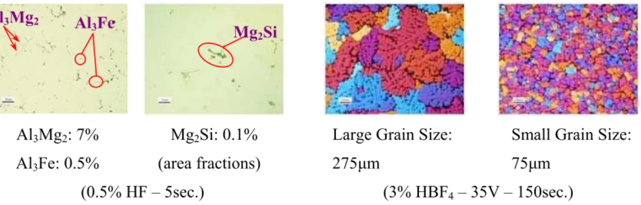
The microstructure and characteristics of the alloys are shown below.
Al3Mg2: 7% Al3Fe: 0.5%
Mg2Si: 0.1% (area fractions)
Large Grain Size: 275μm
Small Grain Size: 75μm
(0.5% HF – 5sec.) (3% HBF4 – 35V – 150sec.) Al3Mg2 Al3Fe
Mg2Si
2.3 6061-T61 Wrought Aluminum Alloy
The chemical composition of the 6061-T61 wrought aluminum alloy is presented in the following Table 2.
Table 2: Chemical composition (w.t.%) of 6061 wrought aluminum alloy
Mg Si Fe Cu Cr Mn Ti
0.900 0.640 0.380 0.256 0.211 0.033 0.018
The alloy was given typical T61 heat treatments (540°C-1h, Cold water quench-20°C, Artificial aging for 8h at 175°C) followed by sufficient material removal, as well as modified T61 heat treatments which included up-hill quenching of the solutionized samples to produce specimens with low residual stress levels.The microstructure and characteristics of the 6061-T61 wrought aluminum alloy are shown in the following figure.
Figure 2: Microstructure and characteristics of the 6061-T61 wrought alloy.
2.4 6061-T61 FSW
This alloy has a chemical composition identical to that of the wrought alloy used in this study. Indeed, the wrought alloy served as the base material for the FSW process. No post-weld heat treatments were used in this study.
2.5 Cold Spray 6061-T61
A consolidated cold spray 6061 block was provided by the ARL. The block was then Hip-ed and T6-ed for our fatigue crack growth studies.
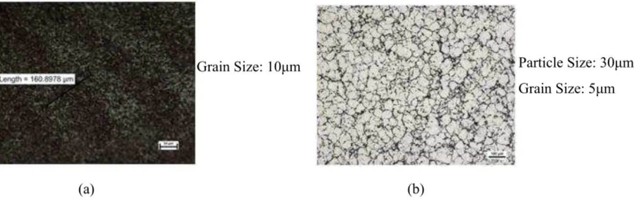
(a) (b)
Figure 3: Microstructure and characteristics of the 6061-T61 (a) FSW and (b) Cold Spray alloys.
Mg2Si
α-Al(CrFe)Si: 2.5% Mg2Si: 0.5% (area fractions) (3% HBF4– 30V – 180sec.)
Grain Size: 10μm Particle Size: 30μm
Grain Size: 5μm T
L
α-Al(CrMnFe)Si
2.6 Ti-6Al-4V Wrought Titanium Alloy
Microstructures resulting from mill and beta anneal heat treatments were investigated (Figure 4). In the first case, the alloy was air-cooled after rolling at 955°C and then annealed at 760°C and furnace cooled (Figure 4a). Beta anneal was performed at 1037°C for 30 minutes and the material was air cooled. The alloy was then annealed at 760°C for 2 hours and air cooled (Figure 4b).
α Grain Size: 13μm (a)
Grain Size: 600μm Prior-beta Boundary Width: 1.8μm α Width: 1.2μm
(b) L
S
T
Figure 4: Microstructure and characteristics of the Ti-6Al-4V wrought alloys. Mill-Annealed, (b) β-Annealed
Tensile properties of the examined alloys are presented in Table 3.
Table 3: Elastic Modulus (E), Yield Strength (YS), Ultimate Tensile Strength (UTS) and Total Elongation
(e%) for the investigated alloys tested at room temperature per ASTM E8-08.
Alloy E
(GPa)
YS
(MPa)
UTS
(MPa)
Total Elongation
(e%)
A535-F- Large Grain Size (275µm) 71.4 128.0 219.6 6.3 A535-F- Small Grain Size (75µm) 69.5 131.6 249.5 7.9 6061-T61 (Tension // to Rolling Direction) 64.8 291.6 317.2 17.0 6061-T61 (Tension ┴ to Rolling Direction) 67.5 286.1 318.5 16.4 Ti-6Al-4V Mill-Annealed (Tension // to Rolling
Direction) 121.3 868.0 935.1 17.6
Ti-6Al-4V Beta-Annealed (Tension // to Rolling
Direction) 119.9 926.6 1010.7 10.0
2.7 Fatigue Crack Growth Testing
For long crack growth experiments, compact tension, C(T), specimens with width W=50.8mm (2in.) and thickness B=12.7mm (0.4in) were machined from the A535, 6061-T6 and Ti-6Al-4V alloys. For the FSW 6061, samples with thickness B=6.35mm (0.2in) were used. A notch with 25.4mm (1in.) length, 0.254mm (0.1in.) width and 0.127mm (0.005in.) tip radius was introduced by means of EDM. All specimens were prepared and tested according to ASTM E647 [20]. Experiments were conducted in laboratory air at room temperature (~23°C) and relative humidity 20-50%. The specimens were tested under K-control, first decreasing in order to obtain threshold values (2.54x10⁻⁸mm/cycle) and then increasing up to a growth rate of 2.54x10⁻²mm/cycle. The frequency was set to 20Hz and low, intermediate, and high stress ratios were used, R=0.1, R=0.5 and R=0.7 respectively. Visual measurements were recorded during the K-control tests for data analysis and post test corrections. The compliance technique was used to monitor crack propagation.
In addition to long crack growth testing, corner and surface flaw tension specimens, with a gage cross section of 10.16mm x 5.08mm (0.4in. x 0.2in.) and a grip cross section of 20.32mm x 10.16mm (0.8in. x 0.4in.) were machined from the above alloys with the exception of the cold spray and FSW alloys. Triangular corner flaw and surface flaw in the range of 75μm (0.003in) to 150μm (0.006in.) were introduced in order to study the small crack growth behavior of the alloy. The specimens were tested under constant load at 25Hz and R=0.1 until failure. Crack growth was monitored using a direct current potential drop method.
3 RESULTS AND DISCUSSION
Fatigue crack growth data of the investigated materials as well as fractographic analysis are presented in this section.
3.1 Long Fatigue Crack Growth – Low Residual Stress
In Figure 5, an all alloy comparison of the fatigue crack growth behavior of the alloys with low residual stress level at R=0.1 is presented. The Adjusted Compliance Ratio (ACR) method [21] was used for closure corrections.
1 10 100
ΔKapp (ksi√in)
10 100
ΔKapp (MPa√m)
10-9
10-8
10-7
10-6
10-5
10-4
10-3
10-2
10-1
da
/d
N (
in/cyc)
10-7
10-6
10-5 10-4
10-3
10-2
10-1
100
da/dN (mm/
cyc)
R=0.1 Alloy A535-F Large Grain Size (275μm) A535-F Small Grain Size (75μm) 6061-T61 Crack Perp. Deform. Dir. (L-T) 6061-T61 Crack Para. Deform. Dir. (T-L) ) 6061-T61 Cold Spray Processed 6061-T61 Friction Stir Welded & Ti-6Al-4V Mill-Annealed (L-T)
Ti-6Al-4V β-Annealed (L-T)
1 10 100
ΔKeff-ACR (ksi√in)
10 100
ΔKeff-ACR (MPa√m)
10-9
10-8
10-7
10-6 10-5
10-4
10-3
10-2
10-1
da
/d
N
(
in
/cy
c
)
10-7
10-6
10-5
10-4
10-3
10-2
10-1 100
da
/d
N
(mm/
c
y
c
)
R=0.1 Alloy A535-F Large Grain Size (275μm) A535-F Small Grain Size (75μm) 6061-T61 Crack Perp. Deform. Dir. (L-T) 6061-T61 Crack Para. Deform. Dir. (T-L) ) 6061-T61 Cold Spray Processed 6061-T61 Friction Stir Welded & Ti-6Al-4V Mill-Annealed (L-T)
Ti-6Al-4V β-Annealed (L-T)
(a) (b)
1 10
ΔKapp (ksi√in) 10
ΔKapp (MPa√m)
10-9
10-8
10-7
10-6
10-5
10-4
10-3
10-2
10-1
da
/d
N (in
/c
yc)
10-7
10-6
10-5
10-4
10-3
10-2
10-1
100
da
/d
N
(mm
/c
yc)
LRS Alloy
A535-F - Large Grain Size - R=0.1 @ A535-F - Large Grain Size - R=0.7
1 10
ΔKeff-ACR (ksi√in) 10
ΔKeff-ACR (MPa√m)
10-9
10-8
10-7
10-6
10-5
10-4
10-3
10-2
10-1
da
/d
N (in
/c
yc)
10-7
10-6
10-5
10-4
10-3
10-2
10-1
100
da
/d
N
(mm
/c
yc)
LRS Alloy
A535-F - Large Grain Size - R=0.1 @ A535-F - Large Grain Size - R=0.7
A535-F - Small Grain Size - A535-F - Small Grain Size - R=0.1R=0.1 A535-F - Small Grain Size - R=0.1
(a) (b)
Figure 6: Fatigue crack growth curves comparing A535 alloys. Long crack growth data – before closure
correction, ΔKapp and Long crack growth data – after closure correction, ΔKeff.
3.2 Near-Threshold Crack Growth Mechanisms
The near-threshold behavior of the alloys can be explained through microstructure/roughness-induced closure mechanisms related to the microstructural characteristic features of the alloys, assuming that the contribution of other sources of closure such as plasticity-, oxide- and residual stress-induced closure is small. In the near-threshold regime, the fracture path has a faceted appearance and the level of the fracture surface roughness is dictated by the crack deflection when microstructural characteristic features are encountered, as shown in Figure 7.
For the A535 as-cast aluminum alloys, where the microstructural characteristic dimension is the grain size, the difference in threshold values can be attributed to the different grain size and amount of roughness-induced closure. Assuming rather equiaxed grain structures, the level of crack deflection is higher in the large grain sized alloy than in the small grain sized alloy because of the larger average grain size, 275µm versus 75µm. This creates more rough fracture surfaces (Figure 7) and as a result, larger amounts of roughness-induced closure are introduced in the large grain sized alloy.
A535-F-Large Grain Size-R=0.1
A535-F-Large Grain Size-R=0.7
A535-F-Small Grain Size-R=0.1
High II (1.2E-5) Threshold (1.8E-9)
Threshold (2.4E-9)
High II (2.5E-6)
Threshold (3.1E-9) High II (7.3E-6)
Variation in threshold values was also observed in the 6061-T61 alloys. Although the microstructure of the alloys was the same, the crack was grown in different directions; parallel and perpendicular to the rolling direction. As a result, the grains were oriented in a different fashion resulting in different amounts of roughness-induced closure. More specifically, the higher threshold values observed in 6061-T61 with the crack growing perpendicular to the rolling direction can be attributed to larger crack deflections at the grain boundaries resulting in rougher fracture surfaces and consequently larger amounts of roughness-induced closure. At the other extreme, lower threshold values were observed in both the Cold Spray and the FSW microstructures. This can be explained by the low degree of crack deflection resulting from the fine grain structure.
3.3 Crack Growth Mechanisms in Regions II and III
Contrary to Region I, in Regions II and III closure mechanisms have a smaller impact on crack growth. This can be explained through the increasing crack tip opening displacements (CTOD). As the driving force ΔK increases, which results in gradually less surface interference between the broken surfaces and consequently, the shielding of the crack tip due to closure diminishes.
In Regions II and III, fatigue crack growth mechanisms depend strongly on the microstructural features and properties. The extent of the plastic zone-damaged material ahead of the crack tip is decisive factor for crack propagation. The plastic zone size was calculated using the following equation, developed by Lados et al. [22], which takes into account both plane-stress and plane-strain effects.
2 2 max 1
) (
6
1
2
1
YS n n
combo p
K
r
σ
π
π
−
⎟
⎠
⎞
⎜
⎝
⎛
⎟
⎠
⎞
⎜
⎝
⎛
≈
(1)where
B stress) plane ( r 1.33 stress plane of
degree = ×p
=
n and B = specimen thickness.
In the as-cast A535 alloys, crack growth mechanisms change from transgranular in low-mid Region II to a mixed transgranular-intergranular mode in high Region II to intergranular at very high ΔK levels in Region III. The low and similar yield strength and matrix micro-hardness play an important role in crack propagation, and explain the similar crack growth rates and mechanisms of the two alloys in Region II (Figure 5). Crack propagation is facilitated by both grain boundaries and the weak matrix, which represents an alternative path of least resistance in front of the advancing crack. Thus, the transition to a mixed mode with significant transgranular propagation only occurs at high ΔK. In Region III, the small grain sized alloy has lower growth rates than the large grain sized alloy due to the larger grain boundary that the crack has to overcome.
In the 6061-T61 alloys, the fracture path is faceted and intergranular propagation occurs only at very high ΔK in Region III where the plastic zone envelopes sufficient grain boundary area to allow intergranular propagation. In Region II, the similar crack growth rates for alloys tested at R=0.1 can be attributed to the small size of the plastic zone which does not exceed the average grain size of the alloy even in the upper Region II. This transition occurs earlier in the 6061-T61 alloy with the notch parallel to the rolling direction because the grains are oriented in such a way that more “damaged” grain boundary area is present within the plastic zone, which explains the higher growth rates of the 6061-T61 alloy with the notch parallel to the rolling direction. No evident preference of the crack to interact with the α-Al(CrMnFe)Si phases was observed.
Al
3Fe
Al3Mg2
Al3Fe
Al3Fe
(a) (b) (c)
Figure 8: (a) Crack’s interaction with Al3Mg2 and Al3Fe phases in A535 cast alloys, (b) Crack’s interaction
In the FSW alloys, it is important to consider the microstructural differences that make it unique from the other structural materials. The first difference that is immediately obvious is the ultra-fine nature of the grains, which has the effect of lowering the threshold value. The second microstructural feature is the presence of bands. These bands are regions of similar grain orientation within the nugget. The spacing corresponds to the tool advance per rotation. The fracture path in the FSW is initially smooth. However, there is a marked transition from no band interaction to a “sawtooth” growth regime, where the crack interacts with the bands. This transition occurs at approximately ΔK ~ 6.6 MPa√m in this case.
(a) (b) (c)
Figure 9: Crack interaction with banding at different ΔK. (a) ΔK< 6.6MPa√m, (b) ΔK=6.6MPa√m, and (c)
ΔK=22MPa√m.
In the mill-annealed Ti-6Al-4V the transgranular mode of propagation, through the α grains, in low Region II can be attributed to the small size of the plastic zone which is smaller than the average α grain size. However, with increasing ΔK the plastic zone size increases and as a result a mixed mode of propagation is observed in mid Region II (Figure 8c). Finally, in Region III, crack propagation occurs mainly through the interface between alpha and beta.
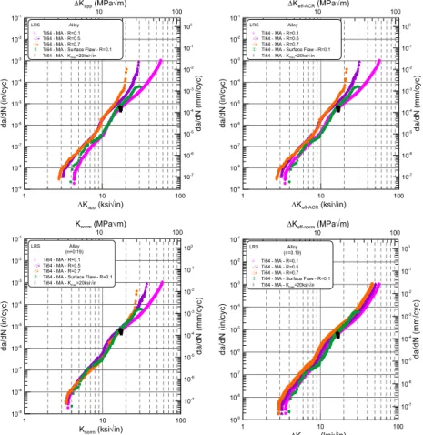
3.4 Data Reduction
Two examples of data reduction are given below based on the normalization technique.
The purpose of the technique is to represent the material’s intrinsic fatigue crack growth behavior using a single, master curve free of remote closure, residual stress and stress ratio effects from which predictions can be made. Data normalization is done by using the following equation:
(
)
nres n
eff
norm
K
K
K
K
=
Δ
1−⋅
max+
(2)After normalizing the data, a single curve is selected to re-introduce stress ratio effects based on Walker’s equation:
(
)
nnorm norm
eff
K
R
K
=
⋅
−
10 100 ΔKapp (MPa√m)
1 10 100
ΔKapp (ksi√in)
10-9 10-8 10-7 10-6 10-5 10-4 10-3 10-2 10-1
LRS Alloy & Ti64 - MA - R=0.1 Ti64 - MA - R=0.5 Ti64 - MA - R=0.7 Ti64 - MA - Surface Flaw - R=0.1 $ Ti64 - MA - Kmax=20ksi√in
10-7 10-6 10-5 10-4 10-3 10-2 10-1 100 da/d N ) c da /dN ( in/cy c ) mm /c y (
1 10 100
ΔKeff-ACR (ksi√in)
10 100
ΔKeff-ACR (MPa√m)
10-9 10-8 10-7 10-6 10-5 10-4 10-3 10-2 10-1 da /dN ( in/cy c ) 10-7 10-6 10-5 10-4 10-3 10-2 10-1 100 da/d N ( mm /c y c )
LRS Alloy & Ti64 - MA - R=0.1 Ti64 - MA - R=0.5 Ti64 - MA - R=0.7 Ti64 - MA - Surface Flaw - R=0.1 $ Ti64 - MA - Kmax=20ksi√in
1 10 100
Knorm (ksi√in)
10 100
Knorm (MPa√m)
10-9 10-8 10-7 10-6 10-5 10-4 10-3 10-2 10-1 da/d N ( in/cy c ) 10-7 10-6 10-5 10-4 10-3 10-2 10-1 100 da /d N (mm/ c y c )
LRS Alloy (n=0.19) & Ti64 - MA - R=0.1 Ti64 - MA - R=0.5 Ti64 - MA - R=0.7 Ti64 - MA - Surface Flaw - R=0.1 $ Ti64 - MA - Kmax=20ksi√in
1 10 100
ΔKeff-norm (ksi√in)
10 100
ΔKeff-norm (MPa√m)
10-9 10-8 10-7 10-6 10-5 10-4 10-3 10-2 10-1 da/ dN ( in/ cy c ) 10-7 10-6 10-5 10-4 10-3 10-2 10-1 100 da/ d N ( mm /c y c )
LRS Alloy (n=0.19) & Ti64 - MA - R=0.1 Ti64 - MA - R=0.5 Ti64 - MA - R=0.7 Ti64 - MA - Surface Flaw - R=0.1 $ Ti64 - MA - Kmax=20ksi√in
Figure 10: Data normalization for mill-annealed Ti-6Al-4V.
1 10
ΔKapp (ksi√in)
10 ΔKapp (MPa√m)
10-9 10-8 10-7 10-6 10-5 10-4 10-3 10-2 10-1 da/d N ( in /cyc ) 10-7 10-6 10-5 10-4 10-3 10-2 10-1 100 da/dN (mm/c yc)
LRS Alloy 6061-T61 - R=0.1 (L-T) 6061-T61 - R=0.5 (L-T) 6061-T61 - R=0.7 (L-T) ! 6061-T61 - Kmax=10ksi√in
1 10
ΔKeff-ACR (ksi√in)
10
ΔKeff-ACR (MPa√m)
10-9 10-8 10-7 10-6 10-5 10-4 10-3 10-2 10-1 da/d N ( in /cyc ) 10-7 10-6 10-5 10-4 10-3 10-2 10-1 100 da/dN (mm/c yc)
LRS Alloy 6061-T61 - R=0.1 (L-T) 6061-T61 - R=0.5 (L-T) 6061-T61 - R=0.7 (L-T) ! 6061-T61 - Kmax=10ksi√in
1 10
Knorm (ksi√in)
10 Knorm (MPa√m)
10-9 10-8 10-7 10-6 10-5 10-4 10-3 10-2 10-1 da/ dN ( in/ c y c ) 10-7 10-6 10-5 10-4 10-3 10-2 10-1 100 da/ d N ( mm /c y c )
LRS Alloy (n=0.25) 6061-T61 - R=0.1 (L-T) 6061-T61 - R=0.5 (L-T) 6061-T61 - R=0.7 (L-T) ! 6061-T61 - Kmax=10ksi√in
1 10
ΔKeff-norm (ksi√in)
10 ΔKeff-norm (MPa√m)
10-9 10-8 10-7 10-6 10-5 10-4 10-3 10-2 10-1 da /dN ( in/cyc) 10-7 10-6 10-5 10-4 10-3 10-2 10-1 100 da/dN ( mm/ c y c )
LRS Alloy (n=0.25) 6061-T61 - R=0.1 (L-T) 6061-T61 - R=0.5 (L-T) 6061-T61 - R=0.7 (L-T) ! 6061-T61 - Kmax=10ksi√in
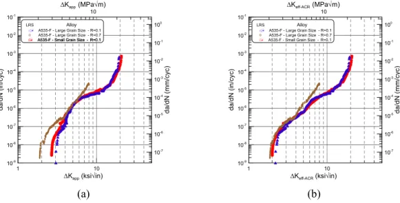
3.5 Small Fatigue Crack Growth
In Figure 12(a), small fatigue crack growth data are presented for A535-F- Large grain sized alloy and mill-annealed Ti-6Al-4V. The A535-F – Large grain sized alloy small crack growth data are characterized by lower threshold value and higher growth rates than the long crack growth and closure corrected data, which shows that closure corrective methods do not account for microstructural effects. On the other hand, the Ti-6Al-4V small crack growth data are similar to the closure corrected data which proves that the initial notch is physically small.
Figure 12: (a) Small fatigue crack growth data and (b) Corner flaw in A535-F- Large grain sized alloy and surface flaw in mill-annealed Ti-6Al-4V.
4 CONCLUSIONS
Near-threshold behavior of the alloys was explained through roughness-induced closure mechanisms. Ultra-fine grains reduce crack deflection and therefore lower the threshold value. The extent of the plastic zone and its relationship with the size of the “damaged” microstructural features were used to explain the mechanisms of crack advance in Regions II and III.
Among the alloys that were tested Ti-6Al-4V exhibited the greatest fatigue crack growth resistance. Small crack effects were observed in the cast A535-F-Large grain sized alloy and mill-annealed Ti-6Al-4V.
5 ACKNOWLEDGEMENTS
The authors would like to thank the members of the Integrative Materials Design Center (iMdc) for their support and the Army Research Lab (ARL) members for their assistance with the preparation of the cold spray samples.
6 REFERENCES
[1] BUCCI, R.J., “Effect of residual stress on fatigue crack growth rate measurement”, In: Fracture Mechanics: Thirteenth Conference, ed. Richard Roberts, ASTM STP 743, American Society for Testing and Materials, pp. 28-47, 1981.
[2] NELSON, D.V., “Effects of residual stress on fatigue crack propagation”, In: Residual Stress Effects in Fatigue, ASTM STP 776, American Society for Testing and Materials, pp. 172-194, 1982.
[3] W. GEARY, J.E. KING, “Residual stress effects during near-threshold fatigue crack growth”,
International Journal of Fatigue, v. 9, pp. 11-16, 1987.
[4] LADOS, D.A., APELIAN, D., “The effect of residual stress on the fatigue crack growth behavior of Al-Si-Mg cast alloys – mechanisms and corrective mathematical models”, Metallurgical and Materials Transactions A, v. 37, pp. 133-145, 2006.
1 10 100
ΔK (ksi√in)
10 100
ΔK (MPa√m)
10-9
10-8
10-7
10-6
10-5
10-4
10-3
10-2
10-1
da
/dN
(i
n/
cy
c
)
10-7
10-6
10-5
10-4
10-3
10-2
10-1
100
da
/d
N
(m
m/c
y
c)
R=0.1 Alloy
A535-F - Large Grain Size - Long Crack Growth Data A535-F - Large Grain Size - ACR Closure Corrected Data $ A535-F - Large Grain Size - Small Crack Growth Data & Ti-6Al-4V Mill-Annealed - Long Crack Growth Data Ti-6Al-4V Mill-Annealed - ACR Closure Corrected Data Ti-6Al-4V Mill-Annealed - Small Crack Growth Data
A535-F-Large Grain Size
Notch Size: 300μm
Ti-6Al-4V – MA
Notch Size: 75μm
[5] PAO, P.S. et al., “Fatigue crack propagation in ultrafine grained al-mg alloy”, International Journal of Fatigue, v. 27, pp. 1164-1169, 2005.
[6] HANLON, T., KWON, Y., SURESH, S., “Grain size effects on the fatigue response of nanocrystalline metals”, Scripta Materialia, v. 49, pp. 675-680, 2003.
[7] BORREGO, L.P., et al, “Fatigue crack growth in heat-treated aluminum alloys”, Engineering Failure Analysis, 2009.
[8] BORREGO, L.P. et al, “Microstructure dependent fatigue crack growth in aged hardened aluminium alloys”, International Journal of Fatigue, v. 26, pp. 1321-1331, 2004.
[9] HUANG, J.C., SHIN, C.S., CHAN, S.L.I, “Effect of temper, specimen orientation and test temperature on tensile and fatigue properties of wrought and PM AA6061-Alloys”, International Journal of Fatigue, v. 26, pp. 691-703, 2004.
[10] CARLSON, R.L. et al, “Fatigue growth of small corner cracks in aluminum 6061-T651”, International Journal of Fatigue, v. 19, pp. S119-S125, 1997.
[11] MANN, T., HARKEGARD, G., STARK, K., “Short fatigue crack growth in aluminum alloy 6082-T6”,
International Journal of Fatigue, v. 29, pp. 1820-1826, 2007.
[12] TESCH, A. et al, “Short cracks initiated in al 6013-t6 with the focused ion beam (fib)-technology”,
International Journal of Fatigue, v. 29, pp. 1803-1811, 2007.
[13] SHADEMAN, S. et al, “An investigation of the effects of microstructure and stress ratio on fatigue crack growth in Ti-6Al-4V with colony α/β microstructures”, Mechanics of materials, v. 36, pp. 161-175, 2004.
[14] NALLA, R.K. et al, “Influence of microstructure on high-cycle fatigue of Ti-6Al-4V: Bimodal vs. Lamellar Structures”, Metallurgical and Materials TransactionsA, v. 33, pp. 899-918, 2002.
[15] SAXENA, V.K., RADHAKRISAN, V.M., “Effect of phase morphology on fatigue crack growth behavior of α-β titanium alloy – A crack closure rationale”, Metallurgical and Materials Transactions A, v. 29, pp. 245-261, 1998.
[16] WANG, S., MULLER, C., “Fatigue crack closure and crack growth behavior in a titanium alloy with different microstructures”, Journal of Materials Science, v. 33, pp. 4509-4516, 1998.
[17] HEINZ, B., SKROTZKI, B., “Characterization of a friction-stir-welded aluminum alloy 6013”,
Metallurgical and Materials Transactions B, v. 33, n. 3, pp. 489-498, 2002.
[18] THOMAS, W.M., NICHOLAS, E.D., NEEDHAM, J.C., “Friction welding”, v. 612, pp. 244, (5,460,317), 1994.
[19] DAWES, C.J., THOMAS, W.M., “Friction stir process welds aluminum alloys”, Welding Journal, v. 75, n. 3, pp. 41-45, 1996.
[20] ASTM standard E647, “Standard test method for measurement of fatigue crack growth rates”, Annual book of ASTM standards, v. 03.01, 2005.
[21] DONALD, J.K., BRAY, G.H., BUSH, R.W., “An evaluation of the adjusted compliance ratio technique for determining the effective stress intensity factor”, Fatigue and Fracture Mechanics, 29, ed. T.L. Panontin, S.D. Sheppard, ASTM STP 1332 (Philadelphia, PA: American Society for Testing and Materials, pp. 674-695, 1999.