Y. Nakai et alii, Frattura ed Integrità Strutturale, 34 (2014) 246-254; DOI: 10.3221/IGF-ESIS.34.26
Focussed on Crack Paths
In situ observation of rolling contact fatigue cracks
by laminography using ultrabright synchrotron radiation
Y. Nakai, D. Shiozawa, S. Kikuchi, K. Sato, T. Obama
Department of Mechanical Engineering, Kobe University, 1-1, Rokkodai, Nada, Kobe 657-8501, Japan [email protected]
T. Makino, Y. Neishi
Nippon Steel & Sumitomo Metal Corporation, Japan
ABSTRACT. In rolling contact fatigue (RCF), cracks usually initiate from inclusions beneath the surface and
propagate to the contact surface. In the present study, synchrotron radiation computed laminography (SRCL) imaging was performed to observe flaking defects during the RCF of a high-strength steel. Specially fabricated inclusion-rich steel plate specimens were employed in the experiments. For the in situ observation of crack propagation, a compact RCF testing machine was developed, and a 4D analysis scheme was applied to the data obtained by SRCL. RCF tests were carried out near the measurement hatch of the beam line used SRCL to enable the successive observation of crack initiation and growth behaviors. Specimens before and after the occurrence of flaking were observed by SRCL, and flaking defects and cracks under the surface were successfully detected. As a result, details of the crack initiation and flaking process in RCF could be discussed. Shear-type horizontal cracks were found to initiate after the initiation and propagation of tensile-type vertical cracks along inclusions, where the face of the vertical cracks was perpendicular to the rolling direction and rolling surface. Therefore, the formation of vertical cracks is considered to affect shear-type crack formation and flaking, where the shape and length of inclusions also affect the initiation and propagation of vertical cracks.
KEYWORDS. Rolling contact fatigue; Laminography; Ultra-bright synchrotron radiation; 3D imaging.
INTRODUCTION
n rolling contact fatigue (RCF), cracks usually initiate from inclusions beneath the surface, and they propagate to form flakes [1, 2]. Although nonmetallic inclusions are known to have a detrimental effect on the fatigue performance of high-strength steels, the commercial production of steels with very high cleanliness is unrealistic because of the high cost. Thus, it may be possible to control the concentration and size of inclusions to obtain steels with better performance. In particulars, in bearing steels, inclusions have complex shapes and are often lined up, thus forming so-called stringers, and the effects of the shape and distribution of inclusions on RCF should be taken into account. Since phenomena occurring under the surface cannot be observed using conventional microscopes, such as optical and scanning electron microscopes, and it is difficult to observe the fracture surface of flakes because the flaking area is damaged by the rolling steel ball after its emergence, the effect of the configuration of inclusions has not yet been systematically investigated.
Y. Nakai et alii, Frattura ed Integrità Strutturale, 34 (2014) 246-254; DOI: 10.3221/IGF-ESIS.34.26
To discuss the mechanism of RCF crack initiation under the contact surface, Grabulov et al. [3] investigated crack initiation around inclusions by a dual-beam (scanning electron microscopy (SEM)/focused ion beam (FIB)) technique. Since this method is destructive, the crack propagation behavior is difficult to observe, and synchrotron radiation micro computed tomography imaging (SRCT) has been applied for nondestructive observation [4]. Stiénon et al. [5],[6] calculated the stress field around nonmetallic inclusions in bearing steels in RCF tests using 3D shapes obtained by SRCT, which was conducted at the European Synchrotron Radiation Facility (ESRF). They used SRCT imaging for the observation of samples with flaking damage and RCF cracks [7], [8]. In these studies, samples were cut from normal size RCF specimens so that they included damaged areas, and the 3D imaging of damage before flaking provided useful information about the RCF crack initiation and propagation processes. To investigate the effect of the shape of inclusions on crack initiation, artificial defects that simulate stringer-shaped inclusions were introduced in the specimens, and the crack initiation and propagation from the artificial defects were observed. For successive SRCT imaging of the RCF process, samples must be sufficiently small to allow the transmission of X-rays, and the crosssection must be smaller
than 500 μm × 500 μm. Our previous study, however, showed that the mechanism of RCF in a small sample is different
from that in a bulk sample [9]. In the present study, SRCL is applied, which allows the high-resolution, nondestructive imaging of thin plates. This method provides a novel means of observing the 3D shapes of microstructures and cracks in a thin plate. A compact RCF testing machine, which enables simultaneous RCF tests and SRCL observation, was developed, and the crack initiation and propagation behaviors are discussed.
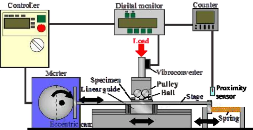
Figure 1: Rolling contact fatigue testing machine for in-situ observation.
MATERIAL AND EXPERIMENTAL PROCEDURE
Material and specimen
he material used in the present study was a bearing steel (modified JIS SUJ2), whose chemical composition (in mass%) was 1.00C, 0.35Si, 0.47Mn, 0.006P, 0.017-0.049S, 1.50Cr, and balance Fe. The material has intentionally contains a high concentration of sulfur to enable the observation of crack initiation from MnS inclusions. The material was forged from an ingot with 65 mm diameter, and its inclusions were intergranular with a preferential alignment along the forging direction. After spheroidizing annealing, specimens were cut from the forged bar, where the transverse crosssection of the bar corresponded to the contact surface of the specimen. The specimen was quenched at 1103 K for 0.5 h and tempered at 453 K for 2 h. The specimens used for SRCL imaging were 10 mm in width, 24 mm in length and 1 mm in thickness. The thickness of the specimens was determined to allow the transmission of X-rays with sufficient intensity for SRCL imaging.
Rolling contact fatigue test
The developed testing machine, which is shown in Fig. 1, is a ball-on-disk-type contact tester. In this testing machine, reciprocal sliding motion is generated by a linear guide and an eccentric cam, and then a steel ball rolls on the specimen linearly and reciprocally, unlike in a Mori-type rolling contact fatigue testing machine in which rolling is in a single direction. Ceramic balls with 6.0 mm diameter and a Young's modulus of 300 GPa were employed as contact balls, where the slide distance of the balls was 3.0 mm. Sample can be easily attached and removed from the developed machine. Fatigue tests were interrupted to conduct SRCL imaging to observe the crack initiation and propagation behaviors.
Y. Nakai et alii, Frattura ed Integrità Strutturale, 34 (2014) 246-254; DOI: 10.3221/IGF-ESIS.34.26
Measurement setup
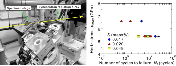
The measurement by SRCL imaging was carried out at the BL46XU beam line of SPring-8 (Super Photon Ring – 8 GeV), which is the brightest synchrotron radiation facility in Japan. Fig. 2 shows the apparatus used for SRCL imaging. The
inclination angle of the axis in the SRCL, , was 30°, and a 37 keV monochromatic X-ray beam was employed. In the
present study, the effective voxel size in the reconstructed the 3D image was 0.74 μm. For the 3D reconstruction, a set of
720 radiographs of a specimen were recorded during 360° rotation, i.e., in increments of 0.5°. The exposure time was 4 s
for the measurements. To utilize the phase contrast effect, an X-ray area detector was set 0.30 m behind the sample. Once the 3D images were reconstructed, they were visualized using Image-J and Amira software. For the 3D representation of inclusions and cracks, a region-growing procedure was employed to segment them, where a gray value threshold between the matrix and air was employed to produce binarized 3D images.
Specimen stage Synchrotron radiation X-ray
105 106 107 108
4 5 6 7 8
Number of cycles to failure, (cycles)Nf
Her
tz
str
ess,
(G
Pa
)
pma
x
S (mass%) 0.017 0.020 0.049
Figure 2: SRCL imaging apparatus Figure 3: S-N curves.
EXPERIMENTAL RESULTS
Fatigue life
he relation between the maximum Hertz stress, pmax, and the number of cycles to flaking is shown in Fig. 3, where
circular, triangular, and square marks indicate the results for materials with sulfur concentrations of 0.017, 0.020, and 0.049 mass%, respectively. An increase in the sulfur concentration resulted in a decrease in the flaking life. It has been reported that the fatigue strength is not affected by the cleanliness (concentration of inclusions) of specimens [1].
The size of inclusions, however, affects the fatigue life, i.e., larger inclusions reduce the fatigue strength [10]. For the
present material, an increase in the sulfur concentration increased the number of inclusions, particularly the number of large inclusions.
Y. Nakai et alii, Frattura ed Integrità Strutturale, 34 (2014) 246-254; DOI: 10.3221/IGF-ESIS.34.26
Specimen with sulfur concentration of 0.020 mass%
Fig. 4 shows an optical micrograph of specimen with a sulfur concentration of 0.020 mass% after N = 1.10×10⁷ cycles
(shortly after appearance of cracks at the rolling surface), where pmax, was 5.39 GPa. It indicates that a small crack of
length approximately 40 μm formed from an inclusion and propagated perpendicular to the ball-rolling direction. After
the formation of the crack at the surface, successive observations by SRCL and RCF tests were conducted at SPring-8.
Flaking was found to occur at Nf =1.295×10⁷ cycles around the site where the surface crack first appeared as shown in
Fig. 5.
200 m
50 m
Rolling direction
Crack
Rolling direction
(a) Flaking (b) Enlarged view of flaking
Figure 5: Optical micrograph of surface at flaking. (pmax = 5.39 GPa, Nf= 1.295×10⁷ cycles).
3D images of inclusions and cracks observed by SRCL at N = 1.10×10⁷ cycles, 1.168×10⁷ and 1.295×10⁷ cycles are
shown in Fig. 6, where (A) is a top view, (B) is a side view of the specimen, and (C) is the view from the rolling direction.
Inclusions are indicated in orange. In (a) and (b), the shape of crack after N = 1.10×10⁷ cycles is shown in red, and the
extension of the crack from N = 1.10×10⁷ cycles to 1.168×10⁷ cycles is shown in white. As shown in the figure, the
surface crack in Fig. 4 appears to form from a cylindrical inclusion with a length of about 30 μm, that reaches the surface,
and the crack face is perpendicular to the rolling direction. At N = 1.10×10⁷ cycles, the vertical crack had propagated
further than the depth of the starter inclusion. Slight growth of the crack in the depth direction was observed at N =
1.168×10⁷ cycles. The shape of the flake at Nf = 1.295×10⁷ cycles is indicated in purple in Fig. 6 (c). It can be concluded
that the flake formed around the site where the vertical crack was observed. The shape at the surface obtained by SRCL is similar to that obtained by optical microscopy as shown in Fig. 5. Since the depth of the flaking is almost the same as that of the vertical crack, the formation of the vertical crack must have affected the formation of the flake although part of the vertical crack remained at the bottom of the flake as can be seen in Fig. 5 (b).
Specimen with sulfur concentration of 0.049 mass%
Fig. 7 shows a SEM image of a crack initiation site at the surface (N = 6.00×10⁶ cycles, shortly after crack initiation at the
surface), where pmax, was 5.39 GPa. A small crack, which is perpendicular to the ball-rolling direction, can be observed.
After the initiation of the crack at the surface, observation by SRCL was conducted at SPring-8. Flaking was found to
occur at N =7.67×10⁶ cycles at the site where the surface crack was observed as shown in Fig. 8.
3D images of inclusions and cracks observed by SRCL at N = 6.00×10⁶ cycles, 6.80×10⁶ cycles, 7.10×10⁶ cycles, 7.50×10⁶
cycles, and 7.67×10⁶ cycles are shown in Fig. 9, where (A) is a top view, (B) is a side view of the specimen, and (C) is the
view from the rolling direction. In these figures, red, black, blue, green, and purple indicate crack at N = 6.00×10⁶ cycles,
6.80×10⁶ cycles, 7.10×10⁶ cycles, 7.50×10⁶ cycles, and 7.67×10⁶ cycles, respectively. It can be seen from these figures that the inclusions, indicated in orange are longer than those in Fig. 6. As shown in Fig. 9, a vertical crack formed from a
cylindrical inclusion with a length of about 60 µm that reaches the surface, and the crack face is perpendicular to the
rolling direction. At N = 6.80×10⁶ cycles, the vertical crack propagated to the deepest point of the starter inclusion
without propagation along the surface. At N = 7.10×10⁶ cycles, a shear-type horizontal crack, which was parallel to the
rolling contact surface, formed at a depth of 35 μm from the surface. From N = 7.10×10⁶ to 7.50×10⁶ cycles, the vertical
Y. Nakai et alii, Frattura ed Integrità Strutturale, 34 (2014) 246-254; DOI: 10.3221/IGF-ESIS.34.26
(A)
x y
z
(C)
(B) Rolling direction Contact ball
(a)N= 1.100×10⁷cycles
Observation direction
(A) (B)
(C)
x y
z x
z y
Rolling direction
Contact surface 50 m Inclusions
■Crack
(A) (B)
(A) (B)
50 m 50 m
(C)
x y
z x
z y
(C)
x y
z x
z y
(b)N= 1.168×10⁷cycles (c)Nf= 1.295×10⁷cycles
■Crack
■Flaking
Figure 6: 3D-images of crack and inclusion.
Y. Nakai et alii, Frattura ed Integrità Strutturale, 34 (2014) 246-254; DOI: 10.3221/IGF-ESIS.34.26
Rolling direction
Rolling direction
Crack
200 m
50 m
(a) Flaking (b) Enlarged view of flaking
Figure 8: SEM micrograph of surface at flaking (pmax = 5.39 GPa, Nf= 7.67×10⁶ cycles).
Another horizontal shear-type crack was also formed from the same inclusion. Its formation site was shallower than that of the displayed vertical crack, but unfortunately it could not be shown in the same figure. Such parallel shear-type cracks were also previously observed in a specimen with an artificial hole, which simulated an inclusion [8].
At N = 7.67×10⁶ cycles, flaking occurred as a result of the propagation of the shear-type crack. The shape of the flake
was similar to that observed on the surface by SEM as shown in Fig. 8.
DISCUSSION
n the specimen with a sulfur concentration of 0.020 mass%, a vertical crack formed from an inclusion whose length
in the thickness direction was 30 μm, and a shear-type crack was formed after the vertical crack reached a length of
50 to 60 μm, which was similar to the initiation condition of the shear-type crack in the specimen with a sulfur
concentration of 0.049 mass%. Since the number of cycles to crack initiation at the surface and flaking are higher for the former specimen, and the propagation of the vertical crack was followed by shear-type crack formation, the length of the inclusion must affect the formation and propagation of the vertical crack and subsequent formation of the shear-type crack. Therefore, the flaking life must be affected by the length of the inclusion.
SEM observation of the surface showed that the depth of flaking was from 20 to 40 μm in both specimens, which is
similar to the depth of the shear-type crack. The depth where the shear stress had the maximum value was 67 μm when
pmax was 5.39 GPa, meaning that the site of shear-type crack formation was not coincident with the position of maximum
shear stress. The existence of a vertical crack may thus change the shear stress distribution.
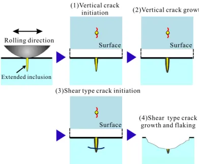
The flaking process in RCF observed in the present study is summarized in Fig. 10. (1) A crack that is perpendicular to the rolling surface and rolling direction forms from an inclusion that is close or adjacent to the rolling surface. (2) The crack propagates vertically in the depth (thickness) direction. (3) After the vertical crack propagates to a critical depth, a shear-type crack forms, which is parallel to the rolling surface. (4) The shear-type crack propagates to induce flaking. In the previously proposed mechanism of RCF, only a shear-type crack was considered in the discussion of the RCF process. In the present study, however, it was shown that the formation of the shear-type crack is induced by a vertical crack that forms before the shear-type crack. The formation of the vertical crack is affected by the shape and size of inclusions, which are determined by the sulfur concentration and heat treatment.
CONCLUSIONS
n the present study, 4D observations of the formation and propagation of the rolling contact fatigue (RCF) tests were performed on a high-strength steel by combining a newly developed compact rolling contact fatigue test machine with synchrotron radiation computed laminography (SRCL).
I
Y. Nakai et alii, Frattura ed Integrità Strutturale, 34 (2014) 246-254; DOI: 10.3221/IGF-ESIS.34.26
Rolling direction
(A) (B)
(C) Contact surface
x y z x z y Inclusions ■Crack x y z x z y (A) (B) (C) ■Crack x y z x z y (A) (B) (C) x y z x z y (A) (B) (C) ■Crack x y z x z y (A) (B)
(C) ■Flaking
(a)N= 6.00×10⁶cycles
(b)N= 6.80×10⁶cycles (c)N= 7.10×10⁶cycles
(d)N= 7.50×10⁶cycles (e)Nf= 7.67×10⁶cycles ■Crack
50 m
50 m 50 m
50 m
50 m
(A) x y z (C) (B) Rolling direction Contact ball Observation direction
Y. Nakai et alii, Frattura ed Integrità Strutturale, 34 (2014) 246-254; DOI: 10.3221/IGF-ESIS.34.26
Rolling direction Surface
Extended inclusion
Surface
Surface (1)Vertical crack
initiation (2)Vertical crack growth
(3)Shear type crack initiation
(4)Shear type crack growth and flaking
Figure 10: Model of flaking mechanism from extended inclusion.
The following results were obtained.
1. To observe RCF cracks and inclusions in a plate specimen, SRCL imaging was carried out at the BL46XU beam line of SPRing-8, which is the brightest synchrotron radiation facility in Japan. Cracks existing beneath the contact surface could be detected with high resolution. Thus, SRCL imaging is a powerful technique for elucidating the crack initiation and propagation behaviors of RCF.
2. RCF tests using the newly developed compact testing machine and SRCL imaging were carried out successively to observe the crack initiation and propagation behaviors. Using this technique, the formation of tensile-type vertical cracks, and shear-type horizontal cracks, and the flaking process were successfully observed.
3. A shear-type horizontal crack initiated after the vertical crack, whose face was perpendicular to the rolling direction and rolling surface, and initiated and propagated along an inclusion. Therefore, the formation of a vertical crack must affect shear-type crack formation and flaking, where the shape and length of the inclusion also affect the initiation and propagation of the vertical crack.
ACKNOWLEDGMENTS
he synchrotron radiation experiments were performed at beam line BL46XU of SPring-8 with the approval of the Japan Synchrotron Radiation Research Institute (JASRI) under proposal numbers 2014A1562, 2014A1770, 2014B1602, and 2014B1890. The authors are grateful for the technical support of Dr. K. Kajiwara (JASRI).
REFERENCES
[1] Murakami, Y., Shimizu, M., Effects of non-metallic inclusions, small defects and cracks on fatigue strength of metals, Trans. Japan Soc. Mech. Eng. A, 54 (1988) 413-425.
[2] Goshima, T., Ueda, K., Shimizu, M., Ishihara, S., Crack growth path emanating from an inclusion and fatigue life prediction due to repeated rolling/sliding contact, Trans. Japan Soc. Mech. Eng. A, 54 (1988) 190-197.
[3] Grabulov, A., Zandbergen, H.W., Investigation of microstructural changes within white etching area (‘butterfly”) under rolling contact fatigue (RCF) using TEM and 3D crack reconstruction by focus ion beam (FIB), in: E. Allison, J.W. Jones, J.M. Larson, and R.O. Ritchie (Eds.), Fourth International Conference on Very High Cycle Fatigue, The Metallurgical Society, Warrendale, Pennsylvania, (2007) 219-226.
[4] Gondrom, S., Zhou, J., Maisl, M., Reiter, H., Kroning, M., Arnold, W., X-ray computed laminography: An approach of computed tomography for applications with limited access, Nuclear Eng. Design, 190 (1999) 141-147.
Y. Nakai et alii, Frattura ed Integrità Strutturale, 34 (2014) 246-254; DOI: 10.3221/IGF-ESIS.34.26
[5] Stiénon, A., Fazekasa, A., Buffièrea, J.-Y., Vincenta, A., Daguierb, P., Merchi, F., A new methodology based on X-ray micro-tomography to estimate stress concentrations around inclusions in high strength steels, Materials Sci. Eng. A, 513-514 (2009) 376-383.
[6] Stiénon, A., Fazekat, A., Buffièrea, J.-Y., Daguierb, P., Merchi, F., Vincent, A., A new methodology for predicting fatigue properties of bearing steels: From X-Ray micro-tomography and ultrasonic measurements to the bearing lives distribution, J. ASTM Int., 7 (2010). DOI: 10.1520/JAI102532.
[7] Shiozawa, D., Nakai, Y., Fukuda, Y., Neishi, Y., Makino, T., Observation of cracks in ccrbon steel under contact rolling fatigue by micro CT imaging using ultra-bright synchrotron radiation, Proc. 15th Int. Conf. Exp. Mech., CD-ROM, (2012) 2635.
[8] Makino, T., Neishi, Y., Shiozawa, D., Fukuda, Y., Nakai, Y., Evaluation of rolling contact fatigue crack path in high strength steel with artificial defects, Int. J. Fatigue, 68 (2014) 168-177.
[9] Shiozawa, D., Makino, T., Neishi, Y., Nakai, Y., Observation of rolling contact fatigue cracks by laminography using ultra-bright synchrotron radiation, Procedia Materials Science, 3 (2014) 154-164.