©2013 Science Publication
doi:10.3844/ajassp.2013.986.999 Published Online 10 (9) 2013 (http://www.thescipub.com/ajas.toc)
Corresponding Author: Sundar Rajan Giri Thulasiraman, Department of EEE, Sathyabama University, Chennai-600 119, India
FUZZY INFERENCE SYSTEM
BASED POWER FACTOR CORRECTION
OF THREE PHASE DIODE RECTIFIER USING
FIELD PROGRAMABLE GATE ARRAY
1
Sundar Rajan Giri Thulasiraman and
2Christober Asir Rajan
1
Department of EEE, Sathyabama University, Chennai-600 119, India 2Department of EEE, Pondicherry Engineering College, Puducherry-605 014,India
Received 2013-07-07, Revised 2013-07-11; Accepted 2013-07-29
ABSTRACT
This study describes a novel method in improving the input current total harmonic distortion as well as power factor of a three-phase diode rectifier circuit. In this method, three bidirectional switches comprising MOSFET and four diodes are used across the three-phase supply and load. In a three-phase rectifier only two diodes conduct at any given time. As a result, the current in the third phase is zero. But in this method, the bidirectional switch corresponding to the third phase is turned ON. The closing of bidirectional switches provides an alternate path for the input current to flow. Once the input voltage crosses zero-voltage axes, the corresponding switch will be triggered. The fuzzy logic based control method is used to generate the triggering pulse for the bidirectional switches. The conduction angle of bidirectional switch is adjusted to make the output power constant and at the rated value for converter operation above and below its rated power. The performances of DC motor drive as well as Induction motor drive are evaluated with this method. The analysis, simulation and experimental results of three phase rectifier are also presented in this study.
Keywords: Bidirectional Switch, MOSFET, Three Phase Diode Rectifier, DC Drives and AC Drives
1. INTRODUCTION
Harmonic current pollution generated by nonlinear loads is a serious problem in power systems. Numerous harmonic standards have been put forward on this issue, for example, IEEE and IEC standards (Halpin, 2005). Since three-phase diode rectifiers are widely used in industry, such as adjustable speed drives and dc power supplies (Thasananutariya and Chatratana, 2009; Chen and Luo, 2001; Grbovic et al., 2001), the harmonics generated by the diode rectifier in the line current is a main concern in power electronics. To eliminate the harmonic current generated by this type of harmonic source, the shunt Active Power Filter (APF) or series APF has been an effective solution (Corasaniti et al., 2009; Singh and Solanki, 2009; Lavopa et al., 2009; Rahmani et al., 2010; Vodyakho and Mi, 2009; Salmeron and Litran, 2010; Bhattacharya and
Chakraborty, 2011). However, the rating of APF is normally small because of its partial power processing property. Hence, it generally features with low cost and small volume. Shunt APF’s are usually paralleled at the ac side. Therefore, both the voltage and the current processed by APF are with alternating values.
flowing capability. In some specific applications, unidirectional PFC topologies such as the Vienna converter (Dalessandro et al., 2008; Chivite-Zabalza et al., 2009) and the series connected dual boost converter (Salmon, 1996; Qiao and Smedley, 2002) are considered. Both bidirectional and unidirectional three-phase PFCs are required to process all the load power. Thus, most of them suffer from higher silicon cost as compared with the APF solutions which require only partial power processing. Multipulse rectifiers, which employ low frequency phase shift transformer to synthesize reasonable line current waveform, are also reported for the reduction of the silicon cost (Chivite-Zabalza et al., 2009; Roux et al., 2009). Due to the application of low frequency transformer, the volume is a critical limitation. A performance of P-I, I-P, Fuzzy and Neuro-Fuzzy Controllers (Khuntia et al., 2010) for Speed Control of DC Motor was compared and it is observed that fuzzy logic based controllers give better responses than the traditional P-I as well as I-P controller for the speed control of dc motor drives. The DC Link Active Power Filter (Du et al., 2012), composed of two series-connected bidirectional boost converters is implemented in three phase diode rectifier, intends to eliminate the input current harmonics. The control structure is complicated.
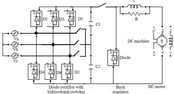
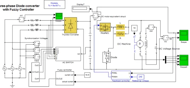
In this study, we propose a simple buck converter at the output stage of three phase diode rectifier with bi directional switches. The buck converter regulates the voltage at the output stage for speed control applications. The fuzzy logic based control method is developed to improving the conduction period of the bi directional switches. The new technique is simulated with DC drive application by PI controller as well as Fuzzy controller and the results are compared.
1.1. Analysis of Proposed Diode Rectifier with
Buck Regulator
The circuit diagram of proposed diode rectifier with buck regulator is shown in Fig. 1. For the circuit analysis, six topological stages are presented in Fig. 2 a to f, corresponding to the 0 to 180 half period. Two main situations can be identified:
In the stage I, III and V, there are only two conducting diodes. As a result, on a conventional three-phase rectifier, the current on the third phase remains null during that interval. In the circuit, the switch associated with the third phase is gated on during that interval. For instance, during the 0 to 30 stage, the bidirectional switch is gated on, so the input current evolves from zero to a maximum value.
(a) (b)
(c) (d)
(e) (f)
Fig. 2. Six topological stages of three phase diode rectifier
In the stage II, IV and VI, there are three conducting diodes, one associated with each phase. The three switches are off, so the converter behaves like a conventional rectifier with input inductors.
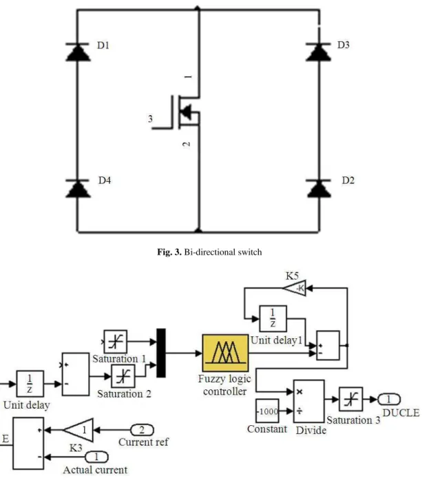
1.2. Bidirectional Switches
When gate circuit is open and Vdd is present, no current flow from drain to source. When gate terminal is made positive with respect to source, current flows from drain to source.
The construction of bi-directional switch using four diodes and MOSFET is shown in Fig. 3.
During positive half cycle of the input voltage, diodes D1 and D2 are forward biased. When gate signal is applied with respect to source, current flow from drain to source. So the input current is supplied to the load through D1, MOSFET and D2.
Fig. 3. Bi-directional switch
Fig. 4. Fuzzy controller
1.3. Fuzzy Controller
The objective is to design fuzzy logic controller that will improve the input current Total Harmonic Distortion (THD) as well as power factor at the input stage by controlling the conduction period of the bidirectional switches.
The FL controller will use both the output current and output current error of the circuit as input and obtain a
control signal as its output. The controls signal will then increase or decrease the conduction period of bi-directional switches that will either achieve the desired power factor at the input stage.
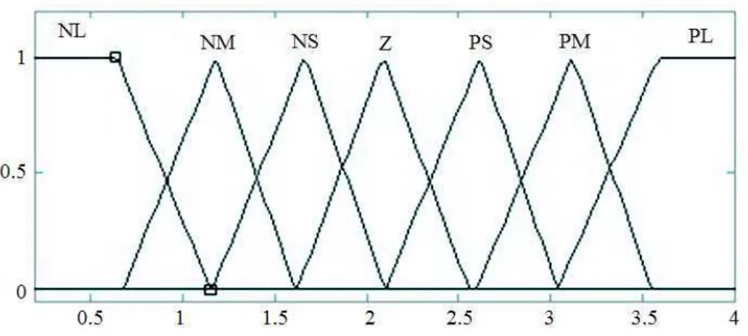
1.4. Fuzzy Rule Base Process
Fig. 5. Fuzzy membership functions of output current I
Fig. 6. Fuzzy membership functions of output current error e
Fig. 8. Surface diagram
Table 1. Linguistics matrix of fuzzy rules
NL NM NS Z PS PM PL
NL NL NL NL NL NM NS Z
NM NL NL NL NM NS Z PS
NS NL NL NM NS Z PS PM
Z NL NM NS Z PS PM PL
PS NM NS Z PS PM PL PL
PM NS Z PS PM PL PL PL
PL Z PS PM PL PL PL PL
Table 2. Fuzzy controller actions for correction in conduction of bidirectional switches
Adjustment Output Current I Error e ∆α
Negative large 3.82 -0.000250 0.555
Negative medium 4.36 -0.000125 1.17
Negative small 4.88 0.000000 2.09
Zero 5.41 0.000125 3.09
Positive small 5.94 0.000250 3.65
Positive medium 6.47 0.000375 3.65
Positive large 8.81 0.001080 3.64
1.5. Fuzzy Variables
Output Current, error (e) in current and Output Control Signal (CS) are detection as Negative Large (NL), Negative Medium (NM), Negative Small (NS), Zero (Z), Positive Large (PL), Positive Medium (PM) and Positive Small (PS)
The linguistics matrix of fuzzy rules for the FL Controller is shown in Table 1.
1.6. Defuzzification
In the defuzzification step, the TSK weighted average formula is employed to produce a single output value Control Signal (CS) that represent the combined effects of all the fuzzy outputs.
1.7. Practical Design Example
compared with a output current of diode rectifier and the difference between the reference current and output current is equal to the error (e). The output current and error are both uses as inputs to the FL controller. The FL controller uses the TSK technique to obtain control signal as its output. The control signal is then fed to the bidirectional switches to modify the conduction period and then input current.
1.8. FL Controller Design
The FL controller uses seven membership functions for the output current and seven membership functions for the output current error. Fuzzy membership functions of output current and error are shown in Fig. 5 and 6 respectively. A fuzzy membership function of control signal is also shown in Fig. 7. The three dimensional FL control surface, of the forty nine membership function rules, shows (Fig. 8) a picture of the characteristics of the controller.
The membership functions could be tuned, to give the set point and this will be reflected by a change in the control surface output. The surface plot represents the fuzzy rule base output value that is added to the defuzzification constant to produce the field current (output). The controller surface shape is steepest where the combined value of both inputs is further away
from zero. Alternatively, the controller surface shape is flattest about the set point:
• Coefficient of Output Current I: 2.76 to 7 • Coefficient of e: -0.0005 to 0.0005
The Fuzzy controller actions for correction in conduction of bidirectional switches are shown in Table 2.
1.9. Simulation Results
1.9.1. Closed Loop Simulation of three Phase
Diode Rectifier with Bidirectional Switch
The closed loop simulation diagram of three phase diode rectifier with bi directional switch is shown in Fig. 9.
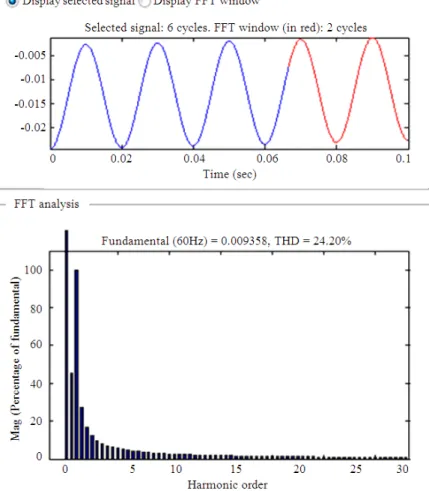
The input current waveform and THD of three phase diode rectifier with bi directional switch is shown in Fig. 10. The THD value of input current is 24.94%.
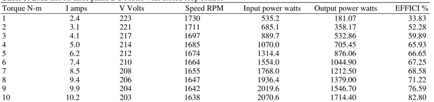
The load test on DC motor with closed loop control was performed and reading was tabulated in the Table 3. In this closed control, input current value is further increased when compared with open loop control and therefore input power is also increases gradually. So the performance of the DC motor is improved.
Table 3. Load test on three phase DC Motor with closed loop control
Torque N-m I amps V Volts Speed RPM Input power watts Output power watts EFFICI %
1 2.4 223 1730 535.2 181.07 33.83
2 3.1 221 1711 685.1 358.17 52.28
3 4.1 217 1697 889.7 532.86 59.89
4 5.0 214 1685 1070.0 705.45 65.93
5 6.2 212 1674 1314.4 876.06 66.65
6 7.4 210 1664 1554.0 1044.90 67.25
7 8.5 208 1655 1768.0 1212.50 68.58
8 9.4 206 1647 1936.4 1379.00 71.22
9 9.9 204 1642 2019.6 1546.70 76.59
10 10.2 203 1638 2070.6 1714.40 82.80
Table 4. Load test on three phase DC Motor with fuzzy logic loop control
Torque N-m I amps V Volts Speed RPM Input power watts Output power watts EFFICI%
1 2.6 218 1756 566.8 183.79 32.43
2 3.2 214 1749 684.8 366.12 53.46
3 4.2 212 1737 890.4 545.42 61.26
4 5.1 210 1726 1071.0 722.62 67.47
5 6.3 209 1719 1316.7 899.61 68.32
6 7.5 207 1707 1552.5 1072.00 69.05
7 8.6 206 1692 1771.6 1239.67 69.97
8 9.5 205 1684 1947.5 1410.07 72.40
9 10.1 203 1672 2050.3 1575.02 76.82
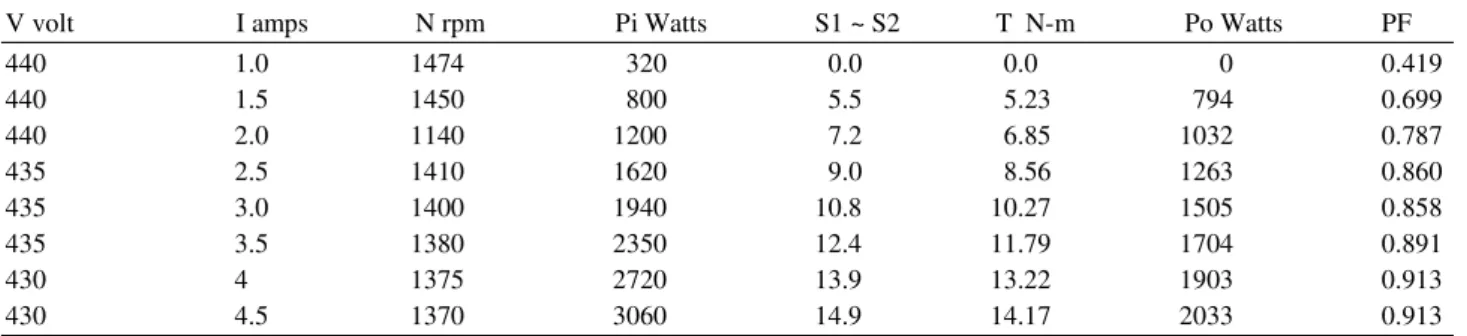
Table 5. Load test using dc-link inverter with bidirectional switches
V volt I amps N rpm Pi Watts S1 ~ S2 T N-m Po Watts PF
440 1.0 1474 320 0.0 0.0 0 0.419
440 1.5 1450 800 5.5 5.23 794 0.699
440 2.0 1140 1200 7.2 6.85 1032 0.787
435 2.5 1410 1620 9.0 8.56 1263 0.860
435 3.0 1400 1940 10.8 10.27 1505 0.858
435 3.5 1380 2350 12.4 11.79 1704 0.891
430 4 1375 2720 13.9 13.22 1903 0.913
430 4.5 1370 3060 14.9 14.17 2033 0.913
Table 6. Load test using dc-link inverter with bidirectional switches
V volt I amps N rpm Pi Watts S1 ~ S2 T N-m Po Watts PF
440 1 1474 320 0.0 0.000 0 0.419
440 1.5 1450 800 5.6 5.323 798 0.699
440 2 1443 1249 7.3 6.990 1048 0.819
435 2.5 1408 1671 9.2 8.952 1289 0.887
435 3 1400 2019 10.9 10.98 1545 0.893
435 3.5 1378 2440 12.8 11.99 1742 0.925
430 4 1372 2810 14.5 13.88 1922 0.943
430 4.5 1369 3192 15.3 14.58 2045 0.952
Fig. 9. Closed loop control of three phase diode rectifier with directional switch
1.10. Implementation of Fuzzy logic Controller
The fuzzy logic controller based simulation diagram of three phase diode rectifier with bi directional switch is shown in Fig. 11.
Fig. 10. The input current waveform and THD of three phase diode rectifier with bi directional switch for closed loop control
Fig. 12. The input current waveform and THD of three phase diode rectifier with bi directional switch for fuzzy logic control
Fig. 14. Variation of torque with input current
Fig. 16. Load test using dc-link inverter
Fig. 17. Input Power factor with variation in line current
So the input current waveform is also improved with sinusoidal form.
The load test on DC motor with fuzzy logic control was performed and reading was tabulated in the Table 4. In this fuzzy logic control, input current value is further increased when compared with closed loop control and therefore input power is also increases gradually. So the performance of the DC motor is improved.
The relationship between torque and efficiency for open loop, closed loop control and fuzzy logic control is shown in Fig. 13. The efficiency of the DC motor is improved in the fuzzy logic control.
The relationship between torque and input current for open loop, closed loop control and fuzzy logic control is shown in Fig. 14. The input current of the DC motor is improved in the fuzzy logic control.
1.11. Experimental Results
The fuzzy logic controller based scheme with resonant inverter at the output stage is demonstrated using FPGA with three phase induction motor as shown in Fig. 15.
Power = 3 HP Current = 4.8 A Voltage = 440 V RPM = 1440
Power factor is calculated by conducting the load test on three-phase induction motor. Load test on three-phase induction motor is conducted with dc-link inverter. For analyzing the improvement in the power factor, the same load test is repeated by fuzzy logic controller based scheme.
1.12. Load Test Using DC-Link Inverter
The circuit diagram for conducting load test on three-phase induction motor is shown in Fig. 16.
Connections are given as per circuit diagram. The load is increased steps by steps and ammeter, voltmeter and wattmeter readings are noted and tabulated in the Table 5.
The input power, output power, torques and power factor are calculated by the following formulas:
1) Input power Pi = W1 + W2 W1, W2 – Wattmeter readings
2) Output power Po = 2пNt watts 60
3) Torque T = (S1 ~ S2).g.r N-m S1, S2 – Spring balance readings in Kg g – Acceleration due to gravity in m/sec 2-9.81 r – Radius of the brake drum in m
4) Power factor cosф = W1 + W2 √3.VL.IL VL – Line voltage in volts IL – Line current in amps
Radius of the brake drum = 0.097 m Multiplication factor = 600×10 /4 = 1500
1.13. Load Test Using Fuzzy logic Controller
Based DC-Link Inverter
Connections are given as per circuit diagram. The load is increased steps by steps and ammeter, voltmeter and wattmeter readings are noted and tabulated in the Table 6.
The relationship between input power factor and line current for Load test using dc-link inverter and fuzzy controller based scheme is shown in Fig. 17.
The power factor of the front-end rectifier is calculated using the equation mentioned with PI controller and Fuzzy Controller. The input power factor of DC link inverter using PI controller is 0.913. Similarly, the input power factor of DC link inverter
using PI controller is 0.9524. So the power factor is improved by 5%.
2. CONCLUSION
The simulation results are obtained for three phase rectifier with open loop and closed loop control show that sinusoidal input supply current waveform presents at the input stage. Experimental results obtained from three phase DC motor for both open loop and closed loop control shows that improved power factor presents at the input stage. A power factor and input current THD improvement for a DC motor load has been verified open loop and closed loop control. Due to the low-frequency operation of the front bi-directional MOSFET switches, the gating circuit is simple and more reliable. The low-frequency operation provides low switching losses. The MOSFET based bi-directional switches conducts only a small fraction of the total cycle, yielding a negligible switch KVA rating. With these excellent rectifier power factor capabilities, the converter will be an excellent energy saver in a clean power environment.
3. REFERENCES
Bhattacharya, A. and C. Chakraborty, 2011. A shunt active power filter with enhanced performance using ANN-based predictive and adaptive controllers. IEEE Trans. Indus. Elect., 58: 421-428. DOI:10.1109/TIE.2010.2070770
Bierhoff, M.H. and F.W. Fuchs, 2009. Active damping for three-phase PWM rectifiers with high-order line-side filters. IEEE Trans. Indus. Elect., 56: 371-379. DOI:10.1109/TIE.2008.2007950
Carlton, D., W. Dunford and M. Edmunds, 1998. Harmonic reduction in the 3-phase 3-switches boost-delta power factor correction circuit operating in discontinuous conduction mode. Proceedings of the 20th International Telecommunications Energy Conference, (EC’ 98), IEEE Xplore Press, San Francisco, CA., pp: 483-490. DOI:10.1109/INTLEC.1998.793579
Chivite-Zabalza, F.J., A.J. Forsyth and I. Araujo-Vargas, 2009. 36-Pulse hybrid ripple injection for high-performance aerospace rectifiers. IEEE Trans.
Indus. Appl., 45: 992-999. DOI:
10.1109/TIA.2009.2018907
Corasaniti, V., M. Barbieri, P. Arnera and M. Valla, 2009. Hybrid active filter for reactive and harmonics compensation in a distribution network. IEEE Trans.
Indus. Elect., 56: 670-677. DOI:
10.1109/TIE.2008.2007997
Dalessandro, L., S.D. Round, U. Drofenik and J.W. Kolar, 2008. Discontinuous space-vector modulation for three-level PWM rectifiers. IEEE Trans. Power
Elect., 23: 530-542. DOI:
10.1109/TPEL.2007.915160
Du, X., L. Zhou, H. Lu and H.M. Tai, 2012. DC link active power filter for three-phase diode rectifier. IEEE Trans. Indus. Elect., 59: 1430-1442. DOI: 10.1109/TIE.2011.2167112
Gensior, A., H. Sira-Ramirez, J. Rudolph and H. Guldner, 2009. On some nonlinear current controllers for three-phase boost rectifiers. IEEE Trans. Indus. Elect., 56: 360-370. DOI: 10.1109/TIE.2008.2003370
Grbovic, P.J., P. Delarue and P.L. Moigne, 2001. A novel three-phase diode boost rectifier using hybrid half-dc-bus-voltage rated boost converter. IEEE Trans. Indus. Elect., 58: 1316-1329. DOI: 10.1109/TIE.2010.2050757
Halpin, S.M., 2005. Comparison of IEEE and IEC harmonic standards. Proceedings of the IEEE Power Engineering Society General Meeting, Jun. 12-16, IEEE Xplore Press, pp: 2214-2216. DOI: 10.1109/PES.2005.1489688
Heldwein, M.L. and J.W. Kolar, 2009. Impact of EMC filters on the power density of modern three-phase PWM converters. IEEE Trans. Power Elect., 24: 1577-1588. DOI:10.1109/TPEL.2009.2014238 Khuntia, S.R., K.B. Mohanty, S. Panda and C. Ardil,
2010. A comparative study of P-I, I-P, fuzzy and neuro-fuzzy controllers for speed control of DC motor drive. Int. J. Elect. Comput. Eng., 5: 287-291.
Lavopa, E., P. Zanchetta, M. Sumner and F. Cupertino, 2009. Real-time estimation of fundamental frequency and harmonics for active shunt power filters in aircraft electrical systems. IEEE Trans. Indus. Elect., 56: 2875-2884. DOI: 10.1109/TIE.2009.2015292
Qiao, C. and K.M. Smedley, 2002. A general three-phase PFC controller for rectifiers with a series-connected dual-boost topology. IEEE Trans. Indus. Appl., 38: 137-148. DOI:10.1109/28.980368
Rahmani, S., N. Mendalek and K. Al-Haddad, 2010. Experimental design of a nonlinear control technique for three-phase shunt active power filter. IEEE Trans. Indus. Elect., 57: 3364-3375. DOI: 10.1109/TIE.2009.2038945
Roux, A.L., H. Mouton and H. Akagi, 2009. DFT-based repetitive control of a series active filter integrated with a 12-pulse diode rectifier. IEEE Trans. Power
Elect., 24: 1515-1521. DOI:
10.1109/TPEL.2009.2015882
Salmeron, P. and S.P. Litran, 2010. Improvement of the electric power quality using series active and shunt passive filters. IEEE Trans. Power Del., 25: 1058-1067. DOI:10.1109/TPWRD.2009.2034902
Salmon, J.C., 1996. Reliable 3-phase PWM boost rectifiers employing a stacked dual boost converter subtopology. IEEE Trans. Indus. Appl., 32: 542-551. DOI:10.1109/28.502165
Singh, B. and J. Solanki, 2009. An implementation of an adaptive control algorithm for a three-phase shunt active filter. IEEE Trans. Indus. Electron., 56: 2811-2820. DOI:10.1109/TIE.2009.2014367
Thasananutariya and S. Chatratana, 2009. Planning study of harmonic filter for ASDs in industrial facilities. IEEE Trans. Indus., 45: 295-302. DOI: 10.1109/TIA.2008.2009503
Vodyakho, O. and C. Mi, 2009. Three-level inverter-based shunt active power filter in phase three-wire and four-three-wire systems. IEEE Trans. Power
Elect., 24: 1350-1363. DOI: