Braz. Arch. Biol. Technol. v.59: e161013 Jan/Dec 2016 Spec Iss 2 Vol.59: e16161013, January-December 2016
http://dx.doi.org/10.1590/1678-4324-2016161013 ISSN 1678-4324 Online Edition
BRAZILIAN ARCHIVES OF BIOLOGY AND TECHNOLOGY
A N I N T E R N A T I O N A L J O U R N A L
Green Energy Generation Using FLC Based WECS With
Lithium Ion Polymer Batteries
Baskar M
1*, Jamuna V
2.
1Pallavan College of Engineering, Kanchipuram, Tamilnadu -631502, India, 2Jerusalem College of Engineering, Chennai, Tamilnadu -631502, India.
ABSTRACT
Green Energy Generation Using Wind energy conversion system is achieved using Lithium Ion Polymer Batteries and Fuzzy logic controller. Presented scheme also provides the constant output power for the stand alone loads like Island, Hills Stations, Ships and Remote locations etc. A fuzzy-logic controller based Wind energy conversion system with permanent magnet synchronous machine is simulated using MATLAB Simulink. The controller provides the constant output voltage in Buck Boost Converter with the wind fluctuations. The SPWM based inverter can be used to produce the constant output voltage with constant frequency. Also a thin and light weight Lithium Ion Polymer Batteries provides the energy back to the Wind energy conversion system , when the wind speed decreases below the base wind velocity. Simulation results are provided to demonstrate the validity of the proposed fuzzy-logic-based controller and comply with the theoretical results. The performance of the system is compared using various controllers.
Key Words: Fuzzy Logic Controller , Sinusoidal pulse width modulation , Wind energy conversion system .
*
Baskar, M et al.
Braz. Arch. Biol. Technol. v.59: e16161013 Jan/Dec 2016 Spec Iss 2 2
INTRODUCTION
Wind energy wins the energy demand, toxic gases production, pollution and difficulty in distribution of electricity to isolated places (Hill Stations, Ship etc...). The less maintenance and space offered by wind energy are the most key factors for receiving vast global attention. Due to the increasing demand on electrical energy, a significant amount of effort is being made to generate electricity from harmless renewable energy sources. The villages are not fulfilling with electricity, some of them are isolated with transmission and distribution network. Only way to utilize the power supply is using renewable energy sources. Well popular renewable energy sources are wind energy and solar energy. Wind energy has a lower installation cost and occupies less space compared to the solar energy. The wind energy system means that it converts kinetic energy (wind energy) in to mechanical energy and then to electrical energy. In this system, the wind velocity decides the output power. Due to the variations in wind velocity , it is difficult to maintain the turbine with constant output and maximum power output for all wind speed conditions1–3. In the wind turbine system, two types of power generations like fixed speed and Variable speed power generations are used 4. Instead of fixed speed power generation, variable speed power generation is most popular. Energy captured by variable speed power generation is higher than the fixed speed power generation. There are various kinds of generators used in WECS such as induction generator (IG), doubly fed induction generator (DFIG) and permanent magnet synchronous generator (PMSG)5 . The PMSG based on WECS can connect to the turbine without using gearbox. The need of gearbox decrease the weight of nacelle PMSG has the more attention because of small in size, low installation cost and also direct driven machine. Hence PMSG works at low speed without decreasing the efficiency, thus usage of gear box can be avoided
6–7
.The Buck or Boost converters are used to give the Variable DC Voltage. The controller is used to give the constant DC voltage for charging the Battery 8-11. In the present method the buck, boost converters are replaced by Buck-Boost converter to give efficient output. The Normal lead acid batteries are exchanged by Lithium Ion Polymer batteries. SPWM based inverter gives the smooth variations. Finally, WECS is simulated for different wind speeds with different controllers 12-13 and the outputs are obtained.
MODELING OF WECS
The configuration of wind energy conversion system is shown in Figure 1. Wind
turbine converts kinetic energy of the wind’s motion to mechanical energy
Braz. Arch. Biol. Technol. v.59: e16161013, Jan/Dec 2016 Spec Iss 2
Figure 1: Configuration of PMSG Based WECS
Actual
Voltage Ref Voltage Fuzzy
Logic Controller
du/dt Firing
Pulse to MOSFET
3φ
SPWM Inverter PMSG 3φ Diode
Rectifier
DC – DC Converter
Battery MU
X
TXr
Amirthasaravanan, A et al.
Braz. Arch. Biol. Technol. v.59: e161013 Jan/Dec 2016 Spec Iss 2 4
Wind Turbine Model
According to Newton’s second law of motion
(1)
An object having the mass m and velocity v, then the kinetic energy of that mass is equal with work done in displacing that object from rest to some distance s under a force F 15
then
(2)
According the third equation of motion
(3)
(4)
Initial velocity of object u is zero
(5)
Substitute equation (5) in to (2)
(6)
The power can be obtained by the rate of change of kinetic energy
(7)
(8)
(9)
(10)
Actual mechanical power
(11) Mass flow rate,
(12)
Equation (11) becomes,
(13)
(14)
(15)
Let consider
(16)
=blade tip speed/wind speed
Blade tip speed (m/s) =Angular speed of turbine (w)*R/wind speed Substitute value in equation (16).
(17)
To attain the maximum value of cp, cpis differentiated with respect to ‘ ’
Then,
(18)
The roots of the ‘ ’ are,
Braz. Arch. Biol. Technol. v.59: e16161012 Jan/Dec 2016 Spec Iss 2
(19)
Ρ - Air density
A - Swept area of the wind turbine rotor r -Radius of the wind turbine rotor Substitute equation 19 in to 6
(20)
Expression (15) is the actual wind power. At any instant of time wind power can be written as,
(21)
Pwind - potentially available power in the wind
From equation 21, It is observed that the wind power is proportional to the cube of the wind speed, which means that a small increase in the wind speed will result in a large increase of the wind power.
Moreover the power can also be increased by enlarging the radius of wind turbine rotor radius, since the power is proportional to the square of this rotor radius. This is the reason that more and more large scale wind turbine system (up to 10MW) are being investigated and contemplated
The relationship between the power that is captured by the wind turbine and potential maximum power in the wind can be written as,
(22)
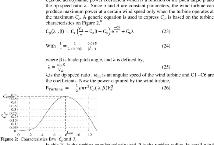
Cpis the aerodynamic power coefficient which is a function of the pitch angle β and
the tip speed ratio . Since ρ and A are constant parameters, the wind turbine can produce maximum power at a certain wind speed only when the turbine operates at the maximum Cp. A generic equation is used to express Cp, is based on the turbine
characteristics on Figure 2.8
β β (23)
With
β
β (24)
where β is blade pitch angle, and is defined by,
(25)
is the tip speed ratio , is an angular speed of the wind turbine and C1 –C6 are the coefficients. Now the power captured by the wind turbine,
(26)
Figure 2: Characteristics B/w
In this,V is the turbine angular velocity and R is the turbine radius. In small wind turbine generation systems, β is rarely changed.
Baskar, M et al.
Braz. Arch. Biol. Technol. v.59: e16161013 Jan/Dec 2016 Spec Iss 2 6
The equivalent circuit consists of two axis namely direct axis and quadrature axis. The quadrature axis rotates ahead with 90 degree to the direct axis. The d–q model is based on the assumption that the stator self-inductance and mutual inductance are either constant or vary sinusoidally with the rotor position16 –19.
Figure 3: Direct axis equivalent circuit of PMSG (d Axis)
The voltage equation from the direct axis equivalent circuit is given by,
(27)
(28)
(29)
Figure 4: Quadrature axis equivalent circuit of PMSG (q Axis) The voltage equation from the Quadrature axis equivalent circuit is given by, (30)
(31)
(32)
With (33)
(34)
(35)
(36)
(37)
(38)
(39)
The torque equation is obtained by (40)
(41)
Braz. Arch. Biol. Technol. v.59: e16161012 Jan/Dec 2016 Spec Iss 2
(43)
(44)
(45)
Hence this is the torque equation for the Permanent Magnet Synchronous Generator (PMSG).If the PMSG is surface mounted permanent magnet,
then the torque equation becomes,
(46)
Mechanical equation
(47)
J=Moment of inertia, B=Viscous friction, Tt=Load torque, Te=Electromagnetic
torque and
m=Mechanical angular velocity.
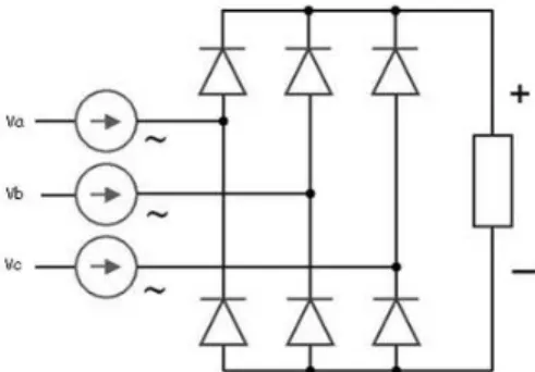
Diode Rectifier
The three phase diode bridge rectifier is employed to convert AC to DC as shown in Figure 5 . The impedance of supply lines is assumed to be low and it is neglected. A distorted three phase voltage system supplies the rectifier with a balanced input. 20–21.
Figure 5: Three phase diode rectifier
The PMSG output is then rectified by means of three phase rectifier whose output voltage can be given as
(48)
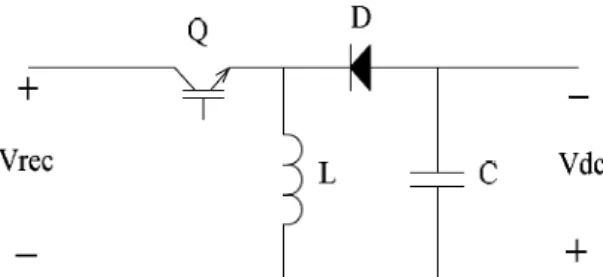
Buck-boost Converter
A buck-boost converter circuit is a combination of the buck converter topology and a boost converter topology in cascade. The output to input conversion ratio is also a product of ratios in buck converter and the boost converter. The output voltage is controlled by controlling the switch-duty cycle 22-24. Buck – boost converter is shown in the Figure. 6. DC voltage Vrec , may be greater than or less than the input
voltage. The output voltage Vdc and output current Idc are given as
(49)
(50)
Where k is the duty ratio. To achieve continuous current the inductor is properly chosen and included. Polarity of Vdc is opposite to that of input voltage as “k”
Baskar, M et al.
Braz. Arch. Biol. Technol. v.59: e16161013 Jan/Dec 2016 Spec Iss 2 8
Figure 6: Circuit Diagram of Buck – Boost Rectifier
To get a constant DC output voltage, the value of “k” in the converter is varied with difference in the reference output voltage and actual output voltage at various wind speed. As the losses are eliminated, the buck-boost converter maintains the constant power like other DC converters. The constant dc voltage for the three phase SPWM inverter is provided by the combination of buck-boost converter with the voltage control loop9.The buck-boost converter along with the voltage control loop maintains a constant dc voltage to the three-phase SPWM inverter.
Batteries
Energy storage device (Battery) is important in the WECS to give the back up source to the Inverter when the wind velocity comes below the base wind speed. Lead Acid Batteries are used to store the electric energy , it occupies more space and produce the less efficiency. Wind generators respond to changing wind conditions by automatically adjusting the angle that the blade makes with the oncoming wind using power from the electrical grid. When the grid fails, there is no load on the generator and the wind generator is in risk of severe damage if the blades are not turned into a neutral position using power provided by the batteries. Presently, lead acid batteries are used for back-up power to readjust the rotors. These, however, require frequent maintenance, which is a significant burden due to the position of the heavy batteries high up on the wind generator and the often remote location. Li poly batteries are one third of the weight, are maintenance-free and have an electronic battery management system that allows checking the status of the battery remotely. A lithium polymer battery, or more correctly lithium-ion polymer battery (abbreviated variously as LiPo, LIP, Li-poly and others), is a rechargeable battery of lithium-ion technology in a pouch format. Unlike cylindrical and prismatic cells, LiPos come in a soft package or pouch, which makes them lighter but also less rigid. Renewable energy generation having a struggle to keep up with the demand from portable products for smaller, lighter and higher-capacity rechargeable. The most recent answer to the challenge is the rechargeable lithium-ion polymer battery, which is expected to serve the growing demand for power-hungry products in the future.
SVPWM Based Inverter
Instead of, maintaining the uniform width of all pulses, the width of each pulse is varied in proportion to the amplitude of a sine wave. The distortion factor and lower order harmonics are reduced significantly. The gating signals are generated by comparing a sinusoidal reference signal with a triangular carrier wave of frequency fc. The modulation index, m, is given by
(51)
Where Vcontrol is the peak amplitude of control
mf = (52)
Braz. Arch. Biol. Technol. v.59: e16161012 Jan/Dec 2016 Spec Iss 2
Fuzzy Logic Controller (FLC) is designed as an alternative to conventional control methods to give better solution of complex systems. The fuzzy logic controller is created with following steps, first step is definition of input and output variables , second step is decision making of fuzzy control rules. After that, fuzzy logic inference is made. Finally, defuzzification and aggregation is made. The overall control scheme of the proposed system is shown in Figure. 7 25–27
Figure 7: Functional Block diagram of FLC
A fuzzy variable has values which are defined by linguistic variables (fuzzy sets or subsets) such as low, medium, high, big, slow, etc. Each fuzzy set is defined by a gradually varying membership function. The shape of fuzzy sets can be triangular, trapezoidal, etc
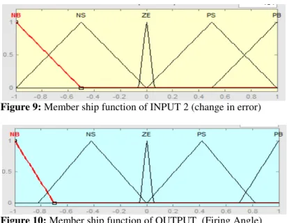
A fuzzy control essentially embeds the intuition and experience of a human operator. The data base and the rules form the knowledge base which is used to obtain the inference relation R. The data base contains a description of input and output variables using fuzzy sets. The rules base is essentially the control strategy of the system. It is usually obtained from expert knowledge or heuristics containing a collection of fuzzy conditional statements expressed as a set of IF-THEN rules. In fuzzy logic controller design, action of identification of the main control variables and action of sets that describe the values of each linguistic variable is very important. The specific structure of the FLC is shown in Figure.7. The input variables of the FLC are the output voltage error, e(n), and the change of this error,
Δe(n). The output of the FLC is the duty cycle of the, δ(n), that regulates the output voltage. Figures. 8 - 10 shows the membership functions of the inputs and output of the Buck Boost Converter. The triangular membership functions are used for the FLC for easier computation. A five-term fuzzy set, Negative Big (NB), Negative Small (NS), Zero (ZE), Positive Small (PS), Positive Big (PB), is defined to describe each linguistic variable.
The fuzzy rules of the proposed Buck Boost DC-DC converter can be represented in a symmetric form, as shown in TABLE I. The Mamdani fuzzy inference method is used for the proposed FLC, where the maximum of minimum composition technique is used for the inference and the center-of-gravity method is used for the defuzzification process.
Baskar, M et al.
Braz. Arch. Biol. Technol. v.59: e16161013 Jan/Dec 2016 Spec Iss 2 10
Figure 9: Member ship function of INPUT 2 (change in error)
Figure 10: Member ship function of OUTPUT (Firing Angle)
Thus, the membership function in Figure. 10 is guaranteed to produce the stable output signal. The design of the focused membership function values depends on the nature of the signal. The control signal value is confined between -1 and 1 owing to the PWM carrier wave. The input signal values are between -1 and 1 because of the error signal, resultant from the difference between output signal and the desired reference signal. Also, most of error values are centered from -0.2 to 0.2. The sharpness of the control signal is very essential for minimizing the error signal to zero in short time, therefore; the pulse membership function is used to configure the control signal fuzzy sets.
Table I : FLC rules for the converter
e(n)/Δe(n). NB NS ZE PS PB
NB NB NS NB PB PB
NS NS ZE NB PS PB
ZE NB NS ZE PS PB
PS NB NB PS PS PS
PB NB NS PB PB PB
RESULT AND DISCUSSON
Braz. Arch. Biol. Technol. v.59: e16161012 Jan/Dec 2016 Spec Iss 2
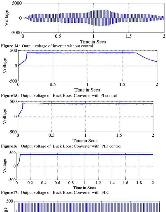
be the constant output voltage and frequency. This problem can be rectified by introducing a controller circuit at the Buck Boost converter. WECS for the closed loop control is simulated with PI , PID controller and FLC. Buck Boost converter obtain constant output voltage by controlling duty cycle of the chopper is shown in Figures 15 -17.
Figure11: Simulated Circuit diagram of PMSG based WECS
Figure12: Output voltage of PMSG
Figure13: Output voltage of Buck Boost Converter without control
Baskar, M et al.
Braz. Arch. Biol. Technol. v.59: e16161013 Jan/Dec 2016 Spec Iss 2 12
Figure 14: Output voltage of inverter without control
Figure15: Output voltage of Buck Boost Converter with PI control
Figure16: Output voltage of Buck Boost Converter with PID control
Figure17: Output voltage of Buck Boost Converter with FLC
Figure18: Output voltage of Inverter with FLC
Table II Comparison of Controllers
Parameters PI PID FLC
Rise Time in sec 0.127 0.076 0.0556
Peak Voltage in volt 440 455 440
Braz. Arch. Biol. Technol. v.59: e16161012 Jan/Dec 2016 Spec Iss 2
Settling Time in sec 0.14 0.1 0.059
Max Peak Overshoot in % 25 40 25
CONCLUSION
This paper illustrates a closed loop strategy of a variable-speed wind energy conversion system connected with grid .The obtained constant DC voltage from Buck Boost converter, is fed as an input voltage to the inverter at variable wind speeds. FLC based converter gives the quick dynamic response, accurate control compared with conventional controllers as given in the table. SPWM can be varied to control frequency of the AC output voltage. Inverter produces the constant output voltage for a Stand-Alone Wind-Driven PMSG. The Simulation is successfully done and open loop / closed loop simulation results are presented. The Simulation results coincide with the theoretical results. In future work the battery will be connected with solar energy system to obtain the hybrid renewable energy conversion system.
ACKNOWLEDGEMENT
I express my deep sense of gratitude to our guide, DR. V. JAMUNA, Professor, Jerusalem College of Engineering for providing an opportunity to work on this project. Also thanks to my family for giving encouragement and support.
REFERENCES
1- Yuanye Xia, Khaled H. Ahmed, and Barry W. Williams “A New Maximum Power Point Tracking Technique for Permanent Magnet Synchronous Generator Based
Wind Energy Conversion System,” IEEE Trans On Power Electronics, December 2011, vol. 26, no. 12.
2- Natalia Angela Orlando, Marco Liserre ,Rosa Anna Mastromauro , and Antonio
Dell’Aquila, “A Survey of Control Issues in PMSG-Based Small Wind-Turbine Systems” IEEE trans on industrial informatics, August 2013, vol. 9, no.3.
3- A. Akhilesh Kumar Gupta B. Himanshu Bhushan C. Paulson Samuel. “Generator Topologies with Power Electronics Converters for a Wind Energy Conversion System: A
Review” in Proc. IEEE Int. Conf.
4- Jiawei Chen, JieChen, and Chunying Gong, “New Overall Power Control Strategy for Variable-Speed Fixed-Pitch Wind Turbines Within the Whole Wind Velocity
Range” IEEE trans on indus electronics, july 2013,vol. 60, no. 7.
5- Y. Amirat, M. E. H. Benbouzid , B. Bensaker ,R. Wamkeue “Generators for
Wind Energy Conversion Systems: State of the Art and Coming Attractions” Journal of Electrical Systems 3-1 (2007)
6- OmidAlizadeh, AmirnaserYazdani, “A Strategy for Real Power Control in a Direct-Drive PMSG-Based Wind Energy Conversion System” IEEE trans on power delivery, vol. 28, July 2013
7- Thanh Hai Nguyen, Dong-Choon Lee, Seung-Ho Song and Eel-Hwan Kim
“Improvement of Power Quality for PMSG Wind Turbine Systems” in proc with int IEEE
conference on 2010
8- Changliang Xia, QiangGeng, XinGu, Tingna Shi, and Zhanfeng Song. “Input– Output Feedback Linearization and Speed Control of a Surface PMSG With the
Boost-Chopper Converter” IEEE trans on indus electro, vol. 59, no. 9,September 2012
Baskar, M et al.
Braz. Arch. Biol. Technol. v.59: e16161013 Jan/Dec 2016 Spec Iss 2 14
10- AbdelouahedMesbahi, AbdellahSaad, Mohamed Khafallah, Omar Bouattane,
AbdelhadiRaihani “Boost Converter analysis to optimise variable speed PMSG Wind Generation System” in Proc. 18th IEEE Int. Conf.
11- Azadeh Safari and Saad Mekhilef, “Simulation and Hardware Implementation of
Incremental Conductance MPPT With Direct Control Method Using Cuk Converter” IEEE transactions on industrial electronics, vol. 58, no. 4, april 2011
12- Akie Uehara, Alok Pratap , Tomonori Goya , Tomonobu Senjyu, Atsushi Yona ,
Naomitsu Urasaki , and Toshihisa Funabashi , “A Coordinated Control Method to Smooth
Wind Power Fluctuations of a PMSG-Based WECS” IEEE trans on energy conversion, vol. 26, no. 2, June 2011
13- Akie Uehara, Alok Pratap , Tomonori Goya ,Tomonobu Senjyu, Atsushi Yona ,
Naomitsu Urasaki ,and T0oshihisa Funabashi “A Coordinated Control Method to Smooth
Wind Power Fluctuations of a PMSG-Based W0ECS” IEEE transactions on energy conversion, vol. 26, no. 2, june 2011.
14- Athanasios Mesemanolis, Christos Mademlis, and Iordanis Kioskeridis ,“High
-Efficiency Control for a Wind Energy Conversion System With Induction Generator” IEEE transactions on energy conversion, vol. 27, no. 4, december 2012
15- Manyonge A. W., Ochieng R. M., Onyango F. N. and Shichikha J. M.
“Mathematical Modelling of Wind Turbine in a Wind Energy Conversion System Power Co efficient Analysis” Applied Mathematical Sciences, Vol. 6, 2012, no. 91, 4527 - 4536 16- Xin Wang, Subbaraya Yuvarajan, and Lingling Fan, “MPPT Control for a PMSG-Based Grid-Tied Wind Generation System” in IEEE Conferance
17- Rodrigues J. M.,Resende F.O., Moreira C.L “Contribution of PMSG based Small Wind Generation Systems to Provide Voltage Control in Low Voltage Networks” IEEE trans on energy conversion, Sept 2013vol. 28, no. 3,
18- Md. Enamul Haque, Michael Negnevitsky, and Kashem M. Muttaqi, “A Novel Control Strategy for a Variable-Speed Wind Turbine With a Permanent-Magnet
Synchronous Generator” IEEE transactions on industry applications, vol. 46, no. 1, january/february 2010
19- Thongam J. s.,Tarbouchi M., Beguenane lR.,Okou A.F., Merabet A., and
Bouchard p “An Optimum Speed MPPT Controller for Variable Speed PMSG Wind Energy Conversion Systems”IEEE conference on Feb 2012
20- Jiacheng Wang, Dewei Xu , BinWu , and Zhenhan Luo“A Low-Cost Rectifier Topology for Variable-Speed High Power PMSG Wind Turbines” IEEE trans on power electro, vol. 26, no. 8, Aug 2011
21- Antonino Di Gerlando, Gianmaria Foglia, Matteo Felice Iacchetti, and Roberto
Perini, “Analysis and Test of Diode Rectifier Solutions in Grid-Connected Wind Energy Conversion Systems Employing Modular Permanent-Magnet Synchronous Generators” IEEE transactions on indus electronics, vol. 59, no. 5, may 2012
22- Shyam, Aswathy B. Raj and Robins Anto B. “PMG Based Wind Energy
Conversion System with Closed Loop Boost Converter” Bonfring International Journal of Power Systems and Integrated Circuits, Vol. 1, Special Issue, December 2011
23- Frede Blaabjerg, Marco Liserre, and KeMa,“ Power Electronics Converters for
Wind Turbine Systems” IEEE transactions on industry applications, vol. 48, no. 2, marc h/april 2012
24- Riad Kadri, Jean-Paul Gaubert, and Gerard Champenois, “An Improved Maximum Power Point Tracking for Photovoltaic Grid-Connected Inverter Based on Voltage-Oriented Control” IEEE transactions on industrial electronics, vol. 58, no. 1, january 2011
25- Diana Petrila, Frede Blaabjerg, Nicolae Muntean, Cristian Lascu “Fuzzy Logic Based MPPT Controller for a Small Wind Turbine System ” IEEE Conference, vol. 28, no. 3, 2012
26- Xiang-Dong Sun, Kang-Hoon Koh, Byung-Gyu Yu, and Mikihiko Matsui,
“Fuzzy-Logic-Based V/f Control of an Induction Motor for a DC Grid Power-Leveling System Using Flywheel Energy Storage Equipment” IEEE trans on indus electronics, vol. 56, no. 8, aug 2009
27- Bader N. Alajmi, Khaled H. Ahmed, Stephen J. Finney, and Barry W.
Braz. Arch. Biol. Technol. v.59: e16161012 Jan/Dec 2016 Spec Iss 2
Maximum Power Point in Microgrid Standalone Photovoltaic System ” IEEE trans on power electro, vol. 26, no. 4, apr 2011