100 Years of Ion Beams: Willy Wien's Canal Rays
Karl WienInstitut fur Kernphysik, TU Darmstadt, Schlogartenstrae 9, D-64289 Darmstadt, GERMANY
April, 1999
When Goldstein's report on the \positive light" (or what is known as \Kanalstrahlen", canal rays) in gas discharge tubes rst appeared in 1886, Willy Wien had just nished his thesis at the Helmholtz Institute in Berlin. Eleven years later he performed his rst experiments on canal rays and found that they consisted of inert, charged and neutral particles. The charged component in canal rays could be deected using electric and magnetic elds, enabling Wien to roughly determine their mass-to-charge ratio. Improving vacuum conditions and detection eciency, Thomson nally resolved the lightest constituents of canal rays: the hydrogen ions H+and H+
2. This marked the beginning
of mass spectrometry. The rst mass spectrographs were parabola-image instruments being used by Thomson to discover isotopes. Until about 1923, canal rays became the most common ion source. Also Aston used canal rays as an ion source for the rst double focussing mass spectrometer. -Wien continued his work on canal rays up to the end of his life (he died in 1928). He investigated their interaction with matter, i.e. the mean free path of canal rays in gases with respect to charge exchange and atomic excitation. His particular interest was addressed to the physics of light emission by canal rays, such as the line spectrum and the splitting of these lines in magnetic and electric elds, the Doppler eect and lifetimes.
I Introduction: How Wien
came to Physics with Canal
Rays
In 1886, Goldstein [1] observed that with an electric discharge in low-pressure gases the discharge seemed to continue through a hole in the cathode, i.e. he saw a bright beam behind the cathode. He called these beams canal rays (\Kanalstrahlen"), as they are formed in front of the cathode and pass through canals in the cathode.
Figure 1. Canal rays in a discharge tube from a sketch by Wien [2]. A = anode, K = cathode.
At that time Willy Wien was 22 years old and had just nished his dissertation on the diraction of light on sharp edges at the Helmholtz Institute in Berlin. Prior to taking his doctorate, he studied Physics at the universities in Gottingen, Heidelberg and Berlin for
only four semesters (two years), an extremely short pe-riod of time for the subject of Physics even then. It was perhaps almost too short for he passed his PhD exam with great diculty. The man who was to be awarded the Nobel prize for his work in theoretical Physics 25 years later almost failed on the math exam.
Willy Wien had a natural inclination and talent for Physics. Nevertheless, for many years he was plagued by doubt as to whether he would be better o following the footsteps of his forefathers. His parents were farm-ers in East Prussia. They originally worked a large holding near Konigsberg, where Willy Wien was born. This was later exchanged for a smaller farmstead follow-ing nancial diculties. The new farm proved no easier to cope with and, to add to the Wien's problems, was also heavily damaged during a re. As Willy was their only child, the Wiens naturally hoped their ospring would take on the farm and carry on their life's work. Willy loved life in the country and was a keen hunter. During his time at university and the years followinghis PhD, he spent a lot of time on the farm, learning how to farm and helping his father. Yet unfortunately he failed to inherit his father's agricultural skills. Looking back, he wrote: \I felt that farming was not my natu-ral vocation; the technical side became easy for me, but my knowledge of livestock, and especially of horses, was lacking and I would never have trusted myself to buy a horse". Worry about his choice of occupation depressed him for many years until the decision was almost made for him in 1889; \severe drought and a failed harvest" forced his father to sell the holding.
Willy Wien was oered the chance to take up a post as assistant to Helmholtz at the Physikalisch-Technische Reichsanstalt in Berlin. Besides working on experiments to create a new unit of light, Wien inves-tigated a great number of topics in theoretical Physics. These included water waves and cyclones which he treated with hydrodynamics and also with the thermo-dynamics of thermal radiation, which later produced the Wien displacement law. This work, for which he was awarded the Nobel prize in 1911, was published in 1896 when he was thirty two.
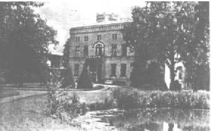
Figure 3. The house where Willy Wien was born on the farm called Gaken west of Konigsberg in East Prussia.
As Helmholtz largely entrusted Wien to carry out his own research, Wien's years in Berlin were relatively
undisturbed and extremely productive. When X-rays were discovered in 1895, Wien was given the task of producing these rays. These constituted his rst exper-iments with particle rays in a vacuum. In the autumn of 1896 he accepted a chair as associate professor at the Technische Hochschule in Aachen where he initially de-voted himself to the study of cathode rays which were used to produce X-rays. The vacuum apparatus left to him by his predecessor, P. Lenard, proved to be very useful. Lenard had invented the Lenard window, among other devices, through which cathode rays could exit into an adjacent vacuum, as opposed to canal rays, which at the time could not be passed through windows.
II Wien's Experiments with
Cathode and Canal Rays in
1897 and 1898
Experimentation with gas discharge started around 1856, when instrument maker Geiler developed a ro-tating mercury pump which could be used to produce a vacuum pressure of probably 0.1 mm Hg. He developed later a diusion pump for pressures down to 10,5 mm Hg. At these pressures, electric gas discharges could be produced between two electrodes in glass tubes whose brilliant light in particular attracted attention. The light produced depends on the ll gas used; besides band spectra it also produces the line spectrum of this gas and was thus often used as a light source for spectral investigations. Using optical methods, Wien repeatedly studied this light, which also originates from canal rays. Goldstein's canal rays - also called positive rays because of their propagation direction - were barely heeded until Wien's rst experiments in 1897. Gold-stein still claimed in 1901 that canal rays could not be deected neither electrically nor magnetically [3]. Many scientists believed that both cathode rays and canal rays were based on processes in the ether, about which there were only very hypothetical ideas at that time. The ether theory did not permit denite pre-dictions about the behavior of the radiation in electric or magnetic elds, for example. Wien made gas dis-charges with both types of rays the subject of his rst experiments.
Catho deRays
and magnetic elds. Perrin [4] showed in 1895 that negative electric charge is transfered by or in them -at the same time Rontgen discovered th-at c-athode rays produce X-rays when they collide with metal.
The original aim of Wien's experiments [5, 6] was to decide \if cathode rays are processes in the ether or are moving, electrically-charged, inert masses". Like his English colleagues, Wien favored the latter option, although there were a number of phenomena which did not quite t the charged particle model. Cathode rays seemed to make their way independent of the path of the current and even passed through thin metal plates without any noticeable drop in velocity. Wien thus had cathode rays pass through an aluminum foil in a tube with an \extreme vacuum", where he monitored the charge by means of an electrometer. He could thus rule out that the charge transfer occurred through the ll gas which had become conductive along the path of the ray. He then determined the velocity of the cathode ray particles and their mass-to-charge ratio with the help of crossed, electric and magnetic elds (Wien lter). In the article he published in Annalen der Physik in 1898 [6] he writes of an m/e value of 5x10,8 CGS. In the International System, this is equivalent to 5x10,12 kg/C. Today's value is 5.685x10,12 kg/C. In spring 1897, J.J. Thomson [7] handed in similar m/e values for publication. He had magnetically deected the rays in the discharge tube gas and then measured the in-tegral transferred load and energy. Due to this m/e ratio determined for cathode rays, Thomson is gener-ally considered to be the scientist who discovered the electron.
CanalRays
Following his investigation of cathode rays, in 1897 Wien [5, 6] turned his attentions to \positive light" which he considered \in its basic nature no dierent from the processes at the cathode". He tried to produce proof of the charge and particle nature of the canal rays using methods similar to those of his cathode ray experiments. He was, however, unable to completely separate the observation area from the discharge area for, despite great eort, he was not successful in nd-ing a substance which the canal rays passed through. It took another 17 years until von Traubenberg [8] ob-served that canal rays can penetrate a 750 A thick gold foil.
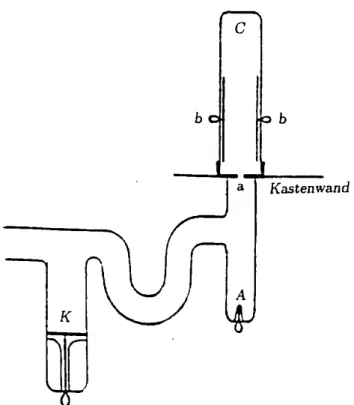
To start with, Wien used the simple glass tube de-picted in Fig. 4 with a cathode \a"(a mesh), an anode \b" and an electrode \C" connected to an electrometer. In order that the discharge area between \b" and \a" be electrically screened, the tube was placed in a grounded
metal box which was connected to cathode \a". The canal rays manifested themselves in a positive charging of \C", even with a relatively high gas pressure, when a very faint light could just be perceived covering the cathode.
Figure 4. Gas discharge tube with a mesh as the cathode behind which canal rays can be observed. The diagram is taken from an article written by Wien [6]. b = anode, a = cathode, C = electrode connected to an electrometer. The lower section of the tube up to the level of the cathode was placed in a grounded tin box.
Figure 5. a: Two sets of tube apparatus for investigat-ing canal rays with an electromagnet SN and an electric deector plate in tube C (not marked). The elds are per-pendicular to one another. The canal rays pass from tube b through a hole in the iron screen aa into tube C. A = anode, aa = cathode.
As Goldstein had already claimed, these canal rays did not change when a magnet was brought near them, as long as the magnet itself did not inuence the dis-charge. With an additional electrode, a perforated metal plate placed between \a" and \b", cathode rays could also be produced if the plate was brought to neg-ative potential relneg-ative to \a". In this case, mixed canal and cathode rays were emitted through grid \a". With higher pressures the charge at \C" was negative, i.e. the canal rays - but not the cathode rays - were obvi-ously absorbed in the gas. As described further on in this article, Wien explored later the mean free path of canal rays in gases in detail.
In order to prove that canal rays could be deected in electric and magnetic elds, the apparatus in Fig. 5a clearly had to be modied. Discharge area and ob-servation area, two glass tubes, were separated by a hole 2 mm wide in an iron plate \aa". In addition, the discharge tube was placed in an iron tube with thick sides. In doing so, the discharge area could be screened against the magnetic eld, which was created in the ob-servation area \C" with the help of an electromagnet SN. Wien tested the residual eld of the electromagnet in \b" with the aid of the cathode rays, which react sensitively to magnetic elds. A magnetic eld in \b" of the same strength as the residual eld had no eect on the canal rays, which were visible on the back wall of tube \C" as a patch of uorescent green. A mag-netic eld of 3250 CGS between the pole faces S and N deected this patch by 6 mm in the opposite direction to the deection of cathode rays, produced by pole re-versal of the electric potential at \A" and \aa". The canal rays were then also deected in an electric eld, whose direction was perpendicular to that of the mag-netic eld (the relevant deector plates in tube \C" are not shown in Fig. 5). From these two deection pro-cesses, Wien calculated a velocity of 3.6x107 cm/s and an m/e ratio of 3.2x10,3 CGS (= 3.2x10,7 kg/C) for the canal rays.
\These experiments show that positively-charged particles move in canal rays"[6]. The m/e ratio would have corresponded to the ions of the oxygen molecule -the gas in -the tube was probably air - yet -the appear-ance of light in the observation area and the patch of green on the glass wall were extremely diuse. Wien pointed out in his article in Annalen der Physik [6] that
\canal rays are a mixture of various rays which can be deected". The deected patch probably looked like a dumbbell with a non-deected brightness maximum, caused by neutral particles, and an oval maximum, which corresponded to deected particles up to the hydrogen ion. Wien presumably interpreted the oval patch of light as a mean deection.
SlowCanalRays
Following his rst m/e ratio for canal rays, Wien went on to observe slow canal rays which transfered positive and negative charge. To this end, he fashioned a discharge tube where the cathode rays could not reach the anode. The area of high voltage drop in front of the cathode (the cathode fall), where the cathode rays are accelerated, is blocked o from the area in front of the anode by a bend in the tube, preventing direct access. The apparatus is shown in Fig. 6, with \K" as the cathode and \a" as the anode, Wien noticed a very diuse ray in \C", which could easily be deected both electrically and magnetically and which carried negative charge to the electrometer electrode \b". M/e ratios could not be determined due to the strong scat-tering of the rays in the magnetic eld. Their velocity was obviously much lower than that of the positive rays formed around the \cathodefal l" .
Figure 6. Gas discharge tube with a large bend in the tube between cathode K and anodes a and A; b = electrode con-nected to an electrometer; C = observation area for negative and positive, slow canal rays. The lower section of the tube up to the level of the anode was placed in a grounded tin box. The diagram is taken from an article written by Wien [6].
is thus split between \a" and \A". An attempt to ex-plain Wien's baing observation with regard to our current understanding of the formation of ions would conclude that rst negative ions are formed by the cap-ture of electrons from gas atoms and accelerated in the direction of both anodes. This produces the \negative light" behind \a". Then, when these negative ions hit electrode \A", positive secondary ions are formed which y in the direction of \a" and enter this anode through the canal if the potential of \A" is slightly more posi-tive than the potential at \a". What we can be sure of is that Wien observed slow ions which were formed in the area of low potential drop in front of the anodes.
Wien compared the path of charged particles in a gas discharge with that during electrolysis and estab-lished that cathode and canal rays can take paths which deviate from the path of the current, producing further evidence of the inertia of these rays, i.e. their particle nature. He obviously had not enough information at that time to fathom the complex impact and ionization processes taking place in the discharge area, thus pro-viding an explanation for the course of the potential drop between the cathode and anode. In his article in Annalen der Physik from 1898 [6], he concludes that it might be expedient to\abandon the terms cathod rays, canal rays and positive light and to speak only of posi-tive and negaposi-tive particles".
III The Beginning of Mass
Spectrometry
After these rst investigations, Wien worked with canal rays during his whole life, - he died in 1928. In numer-ous monographs he describes his personal experiments on this subject. In addition, his assistants Ruchard and Rau as well as many scientists from Germany and from abroad, who were guests at his institute in Wurzburg and later in Munic (after 1920), also con-tributed to the eld. Comprehensive review articles on his \Kanalstrahlen" have been written by him in the handbooks of Radiology [2] and of Experimental Physics [9]. Finally, he denotes with \Kanalstrahlen" all charged and neutral atoms and molecules, which are moving in canal rays. Even such ions, which are pro-duced by thermal processes or by sputtering, are in-cluded, - but not the -rays of the radioactive decay.
At about the same time as Wien, also the English physicist Thomson at Cambridge started his experi-ments on canal rays. Their attempt to split the bended rays into beams of mass-separated particles fail due to the vacuum conditions in the discharge tube and the observation tube. They connect both tubes by a
nar-row capillary, through which the canal rays go, and evacuate them by separate pumps. Nevertheless, it was dicult to establish in the discharge tube a pressure suciently high for the discharge, and in the observa-tion tube a pressure low enough to allow the rays to reach the back wall. The pressure in the observation tube was probably not lower than 10,3mmHg. Within the accelaration gap in front of the cathode, but also in the bending elds, the particles experience charge exchange and get accelerated and bended dierently. Additionally, the rays are broadened due to scattering in the ll gas or the residual gas. The patch of the bended rays on the observation screen remains diuse and more or less strutureless.
Figure 7. Sketch of a parabola-image spectrograph con-structed by Thomson for canal rays in 1897. K cathode, F capillary between discharge and observation tube, S obser-vation screen, AA electric deection plates, NS magnet, P iron shielding. At the left side of the apparatus, the pattern of the bright patch on S is sketched. Number 1 corresponds to the spot of atomic hydrogen, number 2 to that of molec-ular hydrogen. Both drawings are taken from the handbook of Radiology [2].
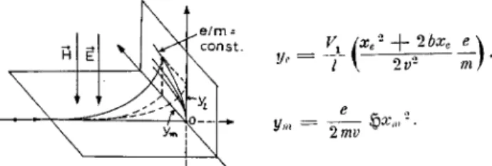
Figure 8. The trajectory of canal rays in parallel electric and magnetic elds. The rays belong to ions of constant mass. The bended rays form a parabolic uorescent strip at the observation screen. The formula of the deections
ye andym by the electric and magnetic elds, respectively,
have been taken from ref. [2]. V1 = potential at the
elec-tric deection plates, l= distance of these plates, xe;m =
distances the ions travel in the two elds, b = distance be-tween the deection plates and the observation screen, ~
H=
magnetic eld strength, v = ion velocity, m = ion mass and e ion charge.
Wien only saw on the back wall of his observation tube a more or less structureless spot. In 1902, he cal-culates for the end of the uorescent strip at a discharge voltage of 30000 Volt an e/m-value of 7545 CGS (see ref. [10]). With respect to the oxygen lling of his discharge tube, this was an unexpected high value. By means of powerful drying agents, the water vapor in the oxygen lling was eliminated. This procedure allowed the high e/m-value, in fact, to almost disappear. Then, Wien obtained e/m = 750 CGS, a value close to that of atomic oxygen (609 CGS).
Thomson improved the method of observation: in-stead of using the uorescence of glass, he directed the rays onto Willemit (Zn2SiO4), a much brighter shining substance. In addition, he mounted a photo lm behind the observation screen, in order to increase sensitivity at long exposure times. He worked at relatively low vacuum pressures, because he added Na, K or Ca to the gas lling, which are easy to ionize. Finally, he was able to observe two oval spots close together as they are sketched in Fig. 7. They agree with the e/m values 104 and 0.5x10⁴ CGS, i.e. the values of the hydrogen ions H+ and H
+ 2 [11].
A characteristic feature of these rst e/m measure-ments by Wien and Thomson was that a large fraction of the canal rays impinging on the observation screen was hydrogen. This was partially attributed to the rel-atively large range of hydrogen atoms or molecules in the residual gas of the observation tube. Then, Wien supposed that the hydrogen is part of the impurites contained in the ll gas. He backed the vacuum tubes over several days and ooded them with the puried ll gas, in order to remove the hydrogen containing residual gas, - but in most cases without success. The hydro-gen patch on the screen seemed to be unavoidable. This led Thomson [12] to assume that the atoms of the canal
rays emit a peculiar charged particle, - similar to par-ticle production by the radioactive decay. Many years later, Konigsberger and Kutschewski [13] proved with canal rays of mercury vapor that the hydrogen fraction can be completely eliminated.
Figure 9. Part of the rst time-of-ight spectrometer con-structed by Hammer [14] for canal rays. The drawing has been taken from the handbook of Wien [2]. NS = magnet for deection of the rays being produced in the discharge tube (not shown), B = rst observation plane, Sp small aperture, A1;1, A1;2, A2;1, A2;2 = electric deection plates,
at the right second observation screen.
These rst e/m determinations were the impetous for many further experiments on this subject by means of rened techniques. One method developed by Ham-mer [14] should be mentioned here, since it employs for the rst time a time-of-ight technique to measure the mass of ions.
Hammer added to the usual parabola-image spec-trograph a time-of-ight apparatus, in order to measure the velocity of certain ions, which were separated from the bundle of canal-ray particles by the parabola spec-trograph. As illustrated in Fig. 9, ions with constant e/m and a narrow velocity range were selected by means of a very small hole drilled in the observation screen of the parabola spectrograph, - i.e. the cross section of the hole covered a small part of one parabolic strip. In order to determine the corresponding e/m value, Ham-mer measured the electric deection yeand the velocity v of the selected ions. Regarding the equation for y
e given in Fig.8, ye,
v, the condensor voltage V
1and some geometrical quantities are sucient to evaluate e/m. The velocityv was determined by measuring the time the ions need to pass the distance between two pairs of deection plates. Both condensers were loaded with help of an oscillating voltage, whose frequency could be precisely tuned. The two electric deections were per-pendicular to each other, - each producing a uorescent line at the screen, together forming an ellipse. When the ions ight time between the condensers is equal to half of the oscillation period, the ellipse degenerates to a line. The corresponding frequency gives the velocity v. Hammer obtained for the H
v= 2:8 10 8cm/s e/m = 9775 CGS.
Today's e/m-value of H+is 9578 CGS, the dierence accounts for 2%.
IV Progress of Mass
Spectrom-etry with Canal Rays up
un-til 1920
The pioneering work of Wien and Thomson stimulated many other scientists to experiment with canal rays and to improve the techniques of mass spectrometry. Wien's interest was focussed more on the physics of canal rays. For many years, canal rays generated in discharge tubes became the most important source of ions. Not only ions of dierent lling gases were stud-ied but also ions of material evaporated inside the dis-charge tube or produced by sputtering. The canal rays were generally guided through narrow capillaries and apertures into the observation tube. Wien developed a special evacuation device (\Durchstromungsmethode") located between discharge and observation area to con-trol the pressures in both tubes (see Fig. 19). He em-ployed this method to study the interaction of canal rays with various gases. In the following, the develop-ment of mass spectrometry based on canal rays will be briey described.
Figure 10. Photographies of canal ray spots taken by Konigsberger and Kilching [15] behind a parabola-image spectrograph. Left: discharge and observation tubes con-tain air (pE and pB are the corresponding pressures in mm
Hg). Right: the lling is CO2.
Soon, the visual observation of the patch at the back wall of the obervation tube was replaced by photogra-phy, - the photo lm was sometimes mounted on the in-side of the tube. Two corresponding pictures taken with a parabola-image spectrograph are shown in Fig. 10. The spots of the bended rays are remarkably sharp in-dicating a narrow velocity range of the particles. Wien was surprised that a carbon spot was not observable, -although the ll gas was CO2.
Figure 11. Another example of canal ray spots taken by Retschinsky [16] with oxygen lling. a) the ll gas contains small amounts of mercury vapor. b) half of the ll gas is H2.
Retschinsky [16] studied the formation of ions in gas mixtures. As can be noticed in Figs. 10a and 10b, sometimes the events of one parabola can accu-mulate at two dierent sites, - this means, `slow' and `fast' ions of the same e/m-value were present. Small amounts of mercury vapor enhance the intensity of the various oxygen ions. Slow oxygen ions, created outside of the cathode-potential drop, disappear when the oxy-gen lling is mixed with 50% hydrooxy-gen. Supposedly, these intensity variations are associated with the dier-ent electron anities of the gases.
In order to detections of canal rays bended by crossed electric and magnetic elds, Wien [17] used small thermocouples, which were warmed by the im-pacting particle beam. Measuring the thermovoltage as a function of the magnetic eld strength, Wien obtained the \Energiekurve" of the canal rays, i.e. of the ions of the ll gas. He discovered that the ion energy did not correspond to the discharge potential, but was 40-50% smaller, - this means, equal to the cathode-potential drop.
Thomson [18] had already analysed the bended canal rays by means of the `transported electricity'. He mounted at the position of the observation screen a Faraday cup behind a ne slit. By changing the mag-netic eld strength he obtained enhanced cup currents, whenever the beam of a certain ion passed the slit. With the help of this method he detected argon ions with charge states up to 3+ and mercury ions up to 7+. An instrument equipped with such a Faraday cup is sketched in Fig. 12. This was built by Dempster [19] in 1916. Substances of interest were evaporated from a glowing wire spiral K. After deection, the canal rays penetrated the Faraday cup through a parabolically formed slit F. With the help of this spectrometer Demp-ster was able to observe a strong mass line at m=3u, i.e. the hydrogen ion H+
Figure 12. Parabola-image spectrograph equipped with a glowing lament K for evaporation. The apparatus has been constructed by Dempster [19]. The ions are detected by means of a Faraday cup F behind a slit Sp. The poles of the magnet S and N are also the electric deection plates. M is an iron shielding.
Figure 13. Current of the Faraday cup as a function of the magnetic eld strenght. The curve was measured with the spectrograph shown in Fig. 12 at a pressure of 0.01 mm Hg. At this pressure, H+
3 is the dominant ion of the mass
spectrum.
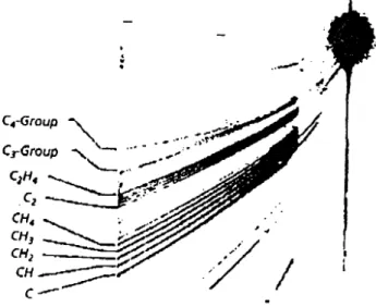
By means of an improved parabola-image spectro-graph, Thomson discovered in 1913, amongst destillates of liquid air, particles having the atomic weight 22 u, which he rst considered as a new gas. Later, it turned out that the corresponding mass line was associated with an isotope of Neon. This was the rst identi-cation of an isotope. Fig. 14 demonstrates that, at these times, mass resolution of parabola-image spec-trographs had been suciently high to resolve neigh-bouring masses at about 30 u. The mass spectrum of methane presented in Fig. 14 exhibits, apart from the relatively week CH+
4 , numerous lighter and heavier ions, which were produced by gas phase reactions in the discharge volume.
Figure 14. A mass spectrum of positive canal rays of methane measured with an parabola-image spectrograph. The photography has been made by Conrad (see Thomson's book [11]).
Concerning mass resolution, a big step forward was the double focussing spectrograph of Aston, which is explained in Fig. 15 following the handbook of Wien [2]. This instrument also utilizes evaporation of probes inside the discharge tube. The canal rays produced in the right tube of the instrument pass through a small hole in the cathode and a narrow slit in front of the de-ection plates, - the latter being the entrance slit of the spectrometer. After traversing the bending magnetic eld, which is perpendicular to the electric eld, the rays impact onto the photographic lm. This lm can be turned away to allow visual observation of the canal-ray patch on a Willemit screen through the window F. The accuracy of mass determination was 1/1200, a re-markably high accuracy for ion beams, which have the broad velocity distribution of canal rays. The instru-ment of Aston compensated the wide energy dispersion in the electric eld by the contrary dispersion in the magnetic eld. Double focussing requires a certain ar-rangement of ion source, bending elds and detection device. The functional dependence of the spectrometer parameters has been derived, for instance, by Wien in his handbook [2].
Figure 15. Mass spectrograph of Aston [20]. The upper part of the gure shows the ion trajectories in the electric eld between the deection plates C and in the magnetic eld M being perpendicular to the electric eld. Ions of the same e/m value but dierent velocities meet at the focal point F. Theoretical calculations concerning the ion optics of this arrangement can be found in the handbook of Wien [2]. The realization of the spectrograph is sketched in the lower part of the gure. At the right: discharge tube with anode A, cathode K and a beam dump G for the cathode rays. The ions pass in front of the deection plates and behind them ne slits Sb and D2 and penetrate then the magnet
eld M. Before making the photograph, the patch of the canal rays on the screen covered by Willemit W can be ob-served through the window F. L1 and L2 are pumps (liquid
air traps).
Figure 16. Mass spectra of gases recorded by Aston's double focussing spectrograph. The gases are denoted at the right end of the photographic stripes. The various ions have been marked by their mass or the symbol of the element. Many of these ions are associated with - mostly organic - impurites of the ll gas.
V Experiments on Physics with
Canal Rays
V.1 Light Emission
Goldstein had discovered canal rays by the light they emitted when travelling through gases and by the uorescent patch they produced on the wall of the dis-charge tube. The study of this light indeed made a ma-jor contribution to the understanding of canal rays and how they reacted with matter. It provided information on the nature of the excited atoms. An extremely im-portant discovery made by Stark in 1905 [22] was that of the Doppler shift. In addition to the unshifted lines, broad stripes appeared in the direction of the longer wavelengths which corresponded to the atoms moving towards the observer (see in Fig. 17). The Doppler shift allowed the observer to dierentiate moving canal ray ions and neutral particles from static gas atoms excited by canal rays. Wien thus examined the ques-tion of whether the light was emitted by charged or uncharged atoms or molecules. In doing so, he studied the light decomposed in spectral lines and emitted from deectable and non-deectable rays and found, for ex-ample, that the Balmer series of hydrogen came from the neutral atoms and the spark-line of oxygen from the ions. Wien carried out numerous other experiments on light emission; three shall be briey described in the following section.
Figure 17. The optical line spectra of O2 and He measured
a) Mean free pathofcanal raysingases Firstly, Wien [24] used the Doppler eect for mea-suring the absolute energy of light associated with a sin-gle spectral line emitted by canal rays. As it is sketched in Fig. 18, the light of the H-line of hydrogen was stud-ied with the help of a high resolution prisma spectro-graph. This light was observed behind the cathode in direction of the canal rays and compared with the radi-ation of a black-body having the same intensity and the same wavelength. Applying the radiation laws, the in-tegral radiation energy was calculated, which accounts for the number of emitted photons. This leads to the number of exciting atomic collisions and subsequently to the cross section for excitation or emission, respec-tively, of the Hlight. Regarding the atomic excitations by collisions as a statistical process, Wien developed a theory using the mean free path as the basic parameter. He also employed the concepts of mean free path and cross section to charge exchange processes, i.e. re-spectively to neutralization of ions and to ionization after neutralization in the plume of canal rays. Such processes were indicated by the fact that a certain frac-tion of the canal rays experienced a smaller deecfrac-tion than pure ion beams.
Figure 18. Apparatus constructed by Wien [23] to study light emission from canal rays by means of a high resolution prisma spectrograph. The electric oven was used as a source of black-body radiation.
Wien noticed charge exchange rst, when canal rays passed through two subsequent regions with magnetic elds: the rst eld did not inuence the neutral com-ponent of the rays. This comcom-ponent, however, turned out to be partially charged, when passing through the second eld. Obviously, originally neutral particles were ionized on their way between the two magnets. He
recognized that charge exchange depended strongly on the pressure in the observation tube and that also neg-atively charged particles were formed. To have a better control of the pressures inside the discharge and obser-vation tubes, Wien developed his \Durchumethode" being sketched in Fig. 19. It was used, for instance, to ll the two tubes with dierent gases or to remove water vapor from the canal rays.
Figure 19. \Durchstromungsmethode" of Wien [26]. E = discharge area, K1, K2, K3 = capillaries, K = adsorbent
cooled by liquid air, N-I and N-II = magnets.
In order to prove his theory of collision statistics, Wien built the apparatus shown in Fig. 20. Behind the cathode, the canal rays y rst through the cap-illary separating discharge and observation area and pass then a series of deection plates, which remove successively the charged particles from the canal rays. Loading the condensers one after the other, the relative number of particles moving in the straight canal-ray beam was measured by means of a thermocouple T. Thus, it was possible to determine the ratio of charged to neutral particles behind the last loaded condenser. Provided that the velocity of the canal rays remains constant over the series of condensers, this ratio should be independent of the number of loaded condensers. It turned out that reliable results were obtainable only with canal rays being generated in very pure gases with a very narrow velocity distribution. By this method, Wien determined, for instance, the mean free path of hydrogen atoms for charge exchange in 0.01 mm Hg oxygen gas. He got a value of 0.167 cm, which leads to a radius of the \Wirkungssphare" (cross section) of 1.5 A. Such results were compared with radii deduced from Bohr's atom model.
b) Life time of excited atomic states
Stark performed numerous optical experiments on canal rays. One of his peculiar ndings was that the light of some spectral lines is observable beyond the sharp border of a canal-ray bundle. His interpretation of this phenomenon was that due to thermal motion some gas atoms escape from the bundle still emitting light with decreasing intensity. This did not happen to all spectral lines. An example for decreasing light emis-sion are the lines of the Balmer series. Wien [27] tried to measure the decay constant for these Balmer lines.
Figure 21. Photographs of a canal ray behind the capillary separating discharge and observation tubes. left: medium vacuum pressure, right: low vacuum pressure (<10
,4mm
Hg). See ref. [2].
He let the canal rays penetrate the observation tube through a short, little capillary. The observation tube was evacuated to the lowest possible pressure; this means only a few atomic collisions occurred in the ex-panding plume. The canal ray bundle was then visible only over a short distance as seen in Fig. 21. The light of this short gleaming strip was split into spectral lines and then used to make a photograph of the strip. The resulting picture was compared with the photographic picture of a slit illuminated by the light of a Geiler tube lled with the same gas as the discharge tube and emitting the same wavelength. A wedge-shaped absorber in front of this slit had weakened the light exponentially over the length of the slit. By tuning the intensity and the exponential decrease of the com-parative light, Wien was able to determine the decay constant of the light emitted from the atoms streaming with a certain velocity into the observation tube. The velocity was measured with help of the Doppler eect. For the light of the Balmer series he obtained a decay constant of 6.4 107/s. This corresponds to 15.6 ns, the rst mean life time of atomic states measured.
c) Electrodynamic splitting of spectral lines
In 1913, Stark [28] made another important discov-ery concerning light emission of canal rays: he found that many spectral lines - in particular those of hydro-gen - split, when the light emitting gas is located in a static electric eld. As an example, Fig. 22 shows the splitting of the H line of hydrogen. Two series of polarized lines are seen, - one polarized parallel (P) to the eld direction, the second one perpendicular (S).
Figure 22. Splitting of the H line of hydrogen in an
elec-tric eld of 104000 V/cm [29]. p = polarized parallel to the electric eld, S = polarized perpendicular. The picture was taken from the handbook of Wien [2].
One year after Stark's discovery, Wien [30] tried to prove if the splitting of spectral lines observed in static electric elds occurs in the same way also, when the light emitting atoms move in a magnetic eld. Such an eect is predicted by Maxwell's theory taking into account the relativity principle: the eld strength af-fecting an atom moving with velocity~vin the magnetic eld ~
His 1 c[
~v ~
H] withcthe velocity of light. The cor-responding splitting was compared by Wien with the splitting caused in a static Coulomb eld ~
Fig. 23 shows the experimental set up used by Wien. The canal rays generated in the discharge tube R y through the capillary C xed between the poles of an electromagnet. The canal-ray light emerging from a slit in the capillary is examined through a central hole drilled in one of the magnet poles by means of an op-tical spectrograph. This means, the direction of ob-servation is perpendicular to the velocity of the canal rays and parallel to the magnetic eld and therefore transversal to the electrodynamic eld as in case of the experiments performed with the electrostatic eld. In order to allow observation of the two dierently polar-ized components, the light passes a lime spar. Wien investigates the H and the H lines of hydrogen. The splitting was in fact hardly visible, - probably due to the broad velocity distribution of the hydrogen atoms, - but the width of the patch agreed well with values published by Stark, who applied a static electric eld, and also with theoretically expected values. Two years later (1916), Wien succeeded to observe also the actual splitting of the component, which is polarized perpen-dicularly to the eld 1
c[ ~v
~
H]. Two splitted lines are seen in Fig. 24. This was one of Wien's most beautiful and smartest experiments.
Figure 23. Sketch of the aparatus used by Wien to detect the line splitting in the electyrodynamic eld 1
c[ ~v
~ H]. R=
discharge tube, C = capillary, M = electromagnet, P = lime spar, L = condenser lense, S collimator slit of the optical spectrograph.
Figure 24. Electrodynamic splitting of the H line of
hy-drogen. In order to reduce the light emitted by atoms of the residual gas, the magnetic eld strength was as high as possible (28000 Gauss) and the velocity of the canal rays correspondingly small (0.36 108 cm/s). A: light polarized
perpendiculary to [~v ~
H]. B: corresponding parallel
polar-ized component of the light. In the center of the splitting A, the line of the not moving atoms is visible.
V.2 Sputtering
This phenomenon had been observed by Plucker [31] at the cathode of the gas discharge tube long before canal rays were discovered. Polished metals became rough after the tube had been in use for a certain pe-riod. This erosion of the cathode surface has an im-portant eect on the composition of the canal rays, as the sputtered material mixes itself with the rays. Canal rays in the observation area also cause a sput-tering of the material they collide with. The amount eroded could be calculated by weighing the cathode, for example. Wien did not carry out any experiments on sputtering himself. A summary was published by Kohlschutter in the 1912 Jahrbuch der Radioaktivitat [32].
The various experiments all showed that the sput-tered amount is proportional to the voltage of the cath-ode fall, i.e. to roughly the energy of the canal rays. A dependence such as this corresponds to the sputtering energy dependency observed today of metals in the keV range. Less explicit was the dependency of the atomic numbers and masses of the ions and irradiated met-als. A comparison with yields won through application of our contemporary sputtering theory shows that the yields measured then were considerably more depen-dent on atomic numbers and masses than the sputtering theory would expect.
Figure 25. Anode made from alkali halides and graphite. This anode was used in discharge tubes as source of sec-ondary ions [33]. a = anode, K = cathode, G = patch of canal rays at the wall of the discharge tube.
been added to the alkali halides to improve their con-ductibility. These canal rays, made up of slow particles coming from the anode (see Fig. 6), contain, according to Reichenheim [34], practically no neutral particles.
VI Canal Rays
,!Ion Beams?
The work of Wien and his assistants has largely con-tributed to explaining the nature of canal rays and their cause (electrical discharge in rareed gases). Wien's experiments always focussed more on their physical as-pects and less on the practical application of the infor-mation gained through them. This is also expressed in the often very detailed theoretical analyses of his ex-periments. The diagram of canal rays and their origin Wien sketched out in his handbook on canal rays [2]; it is not, however, the result of a \gas discharge the-ory". Only certain details of these rays, such as their charge exchange, light emission or the eect of electric and magnetic elds on them, are dealt with theoret-ically. Attempts to describe in theoretical terms the complicated potential steps in a discharge tube, for ex-ample, are summarized in the Handbuch fur Physik, Vol. XXII, from 1956, among other sources.
Wien developed the following ideas on the nature of canal rays in his book [2]: \The place canal rays are formed is what is known as the dark cathode space, where the largest potential dierence can be found". This is where ionization and excitation largely take place by way of electron collision and acceleration of the ionized gas atoms. Negative cathode rays, which move in the opposite direction of the actual canal rays, are chiey produced as secondary ions at the cathode. They can also produce positive ions, i.e. components of the actual canal rays, through collision with the ll gas or by sputtering of the anode. These are joined by photon-induced ionization processes which are respon-sible for the \Nebel Strahlen" (fog rays), for example, which clad the actual canal rays. The canal rays be-hind the cathode mainly consist of neutral, partially-excited atoms or molecules which are formed in front of the cathode or behind it by charge exchange from ions. The gas density in the canal ray is usually so high that charge exchange also occurs behind the cathode. This charge exchange and the wide space in front of the cathode, where ions are accelerated, give rise to a broad spectrum of canal ray particle velocity.
From these characteristics of the canal rays we can deduce that they are not pure ion beams. In order to become so, they must be passed into a vacuum of under 10,4mm Hg and separated from the neutral particles.
Ion sources with currents of ca. 0.1 A and several 10 keV of ion energy have actually been built according to this principle. By way of post-acceleration, ion energies were obtained which were sucient for the rst nuclear reaction experiments. As a rule, modern ion sources no longer use canal rays directly, but make use of pro-cesses which contribute to these in discharge tubes, such as ionization by electron impact, sputtering, secondary ion emission and ionization through photo-eect. From this, we can conclude that Wien rst understood the canal rays to be inert, electrically-charged, atomic par-ticles a hundred years ago were in fact the origin of ion beams.
Acknowledgements
I would like to thank very much Frau Waltraut Wien and Herr Dr. Henning Dwinger, my aunt and my cousin, for the conversations I had with them about their father and grandfather in Munich, where Willy Wien last worked as a professor of Physics. They pro-vided me with a great deal of literature about him, and also with photographs and oprints of his scientic ar-ticles. Further material and also an original canal ray apparatus were available at the Deutsches Museum in Munich, whom I would also like to thank for their as-sistance.
References
[1] E. Goldstein, Sitzungsbericht der Berl. Akad., 25. Juli 1886; Wied. Ann.64, 38 (1898).
[2] W. Wien: Kanalstrahlenin H andbuch fur Radiologie IV, ed. E. Marx, Leipzig Akad. Verlagsges. 1923 [3] E. Goldstein, Verh. der Deut. Phys. Gesellsch. (15)3,
192 (1901).
[4] Perrin, Compt. Rend.121, 1130 (1895).
[5] W. Wien, Verh. der Deut. Phys. Gesellsch. zu Berlin (1897) p. 165 and (1898) p. 10.
[6] W. Wien, Ann. Physik65, 440 (1898).
[7] J.J. Thomson, Phil. Mag. (5)44, 293 (1897).
[8] Rauch von Traubenberg, Nachrichten d. K. Ges. d. W. zu Gottingen 1914.
[9] Handbuch fur Experimentelle Physik, eds. Harms, Wien.
[10] W. Wien, Ann. Phys.8, 260 (1902).
[11] J.J. Thomson,Rays of positive electricity and their ap-plication to chemical analyses, Monographs on Physics, Longmans, London, 1st ed. 1931, 2nd ed. 1921. [12] J.J. Thomson, Phil. Mag.6, 295 (1907).
[14] W. Hammer, Phys. Zeitschr. , 1077 (1911); und Ann. d. Phys.43, 653 (1914).
[15] Konigsberger und Kilching, Phys. Zeitschr.11, 666 und
848 (1910).
[16] Retschinsky, Ann. Phys.47, 525 (1915).
[17] W. Wien, Ann. Phys.33, 33 (1910).
[18] J.J. Thomson, Phil. Mag.24, 245 (1912).
[19] A.J. Dempster, Phys. Rev. N.S. Vol. III, No. 6, 651
(1916).
[20] F.W. Aston, Phil. Mag. 38, 38 (1919) und 39, 611
(1920).
[21] A.J. Dempster, Phys. Rev.9(4), 317 (1918).
[22] J. Stark, Phys. Zeitschr.6, 893 (1905).
[23] J. Stark in: Atomionen der Chem. Elemente, Springerverlag, Berlin 1913.
[24] W. Wien, Ann. d. Phys. , 415 (1907). [25] W. Wien, Ann. d. Phys.27, 1025 (1908).
[26] W. Wien, Ann. d. Phys.27, 1034 (1908).
[27] W. Wien, Ann. d. Phys.60, 597 (1919).
[28] J. Stark, Ann. d. Phys.43, 963 (1914).
[29] J. Stark und G. Wendt, Ann. d. Phys.43, 983 (1914).
[30] W. Wien, Berliner Berichte22(1914).
[31] J. Plucker, Pogg. Ann.103, 90 (1858).
[32] V. Kohlschutter, Jahrbuch der Radioaktivitat 9, 355
(1912).
[33] Gehrcke und O. Reichenheim, Bericht d. Deut. Phys. Ges.8, 559 (1906) und9, 76, 200, 374 (1907).
![Figure 1. Canal rays in a discharge tube from a sketch by Wien [2]. A = anode, K = cathode.](https://thumb-eu.123doks.com/thumbv2/123dok_br/18978448.456145/1.918.519.795.728.1074/figure-canal-rays-discharge-sketch-wien-anode-cathode.webp)


![Figure 10. Photographies of canal ray spots taken by Konigsberger and Kilching [15] behind a parabola-image spectrograph](https://thumb-eu.123doks.com/thumbv2/123dok_br/18978448.456145/7.918.480.830.90.305/figure-photographies-canal-spots-onigsberger-kilching-parabola-spectrograph.webp)
![Figure 17. The optical line spectra of O 2 and He measured by Stark [23]. Upper part: spark-spectrum of oxygen, lower part: spectrum of oxygen-canal rays, which move towards the observer](https://thumb-eu.123doks.com/thumbv2/123dok_br/18978448.456145/9.918.477.830.715.1042/figure-optical-spectra-measured-stark-spectrum-spectrum-observer.webp)
![Figure 19. \Durchstromungsmethode" of Wien [26]. E = discharge area, K 1 , K 2 , K 3 = capillaries, K = adsorbent cooled by liquid air, N-I and N-II = magnets.](https://thumb-eu.123doks.com/thumbv2/123dok_br/18978448.456145/10.918.114.461.603.888/figure-durchstr-omungsmethode-discharge-capillaries-adsorbent-cooled-magnets.webp)
