Development of FSW for composite materials
Flávio André Teixeira Vilhena
Master’s Thesis
Supervisor: Dr. Pedro Moreira Cossupervisor: Prof. Torres Marques
Integrated Master in Mechanical Engineering
Abstract
With the rise in usage of thermoplastic matrix composites, the development of new and better ways to join this kind of materials becomes more interesting. Friction stir welding is a technology, that initially was developed to weld hardly weldable metals. There are some studies made regarding the utilization of friction stir welding in thermoplastic, but little attention was given to the usage of this technology in the welding of composites.
The work developed in the frame of this thesis are focused on the development of a technological solution to apply Friction Stir Welding (FSW) to join composites, in particular in a butt joint configuration. Different tools, rotating shoulder, hybrid and stationary shoulder, were developed to weld a short fibre reinforced composite, PA6 GF30, in a butt joint configuration. The analysis is made qualitatively when regarding the weld appearance and quantitively regarding the forces present during welding and the tool’s temperature.
A design of experiment using a L4 orthogonal matrix was made in order to study which welding
parameters were more influential in the weld strength when using the static shoulder tool. With this work, it was verified that the presence of a static shoulder produced welds with better appearance. The hybrid tool preheated to 269 ºC produced the highest tensile strength specimen with a value of 88.2 MPa, which corresponds to 58.7% of the base materials strength. The static shoulder tool produced the best appearance welds and the best specimen had a tensile strength of 64.1 MPa which corresponds to 42.7% of the base material’s strength.
Desenvolvimento de ligações em FSW para materiais compósitos
Resumo
O aumento de utilização de compósitos de matriz termoplástica, torna interessante o desenvolvimento de novas e melhores formas de união deste tipo de materiais. Soldadura por fricção linear é uma tecnologia inicialmente desenvolvida para soldar metais dificilmente soldáveis. Existem alguns estudos relativos à utilização de friction stir welding (FSW) em termoplásticos, mas pouca atenção foi dada à utilização desta tecnologia em compósitos. Esta tese dedica-se ao estudo de diferentes tipos de ferramentas, de ombro rotativos, híbrido e estático, na soldadura por fricção linear de compósito de fibras curtas, PA6 GF30, numa configuração topo a topo. A análise é feita qualitativamente em relação ao aspeto visual das soldaduras obtidas e quantitativamente no tocante às forças presentes durante a soldadura, assim como a temperatura da ferramenta.
Um DOE foi feito usando uma matriz ortogonal L4 de forma a avaliar quais os parâmetros mais
influentes na tensão de rutura das soldas obtidas utilizando a ferramenta de ombro estático. Com este trabalho ficou evidente que presença de um ombro estático produz soldas com melhor aspeto. A ferramenta híbrida pré-aquecida a 269 °C produziu o provete com maior tensão de rutura, 88.2 MPa, que corresponde 58.7% do material base. A ferramenta com ombro estático produziu as soldas com melhore aspeto visual, o melhor provete produzido com esta ferramenta teve uma tensão de rutura de 64.1 MPa que corresponde a 42.7% do material base.
Acknowledgements
I would like to thank my supervisor Dr. Pedro Moreira for his guidance during this thesis. I am also thankfull for the opportunity of working at LOME. I would like to thank Prof. Torres Marques for his time and availability. I thank Lanxess for donating the Durethan PA 6 GF30 plates used in this thesis. I would like to thank Prof. Miguel Figueiredo and Rui Silva for their assistance with the tensile tests. I would like to thank Mr. Domingos Carvalho for producing the composite welding tool.
Finally, I would like to thank my family for their patience and support through all my education years. Without them none of this would be possible.
Contents
1 Introduction ... 1
1.1 Project goals ... 2
1.2 Structure of the thesis ... 2
2 Thermoplastic Composites ... 3 2.1 Matrix ... 3 2.2 Reinforcement... 5 2.3 Fabrication processes ... 6 2.3.1 Injection moulding ...6 2.3.2 Prepreg ...6 2.4 Joining ... 8 2.4.1 Adhesive bonding ...8 2.4.2 Mechanical fastening ...9 2.4.3 Welding... 11
3 Friction Stir Welding ... 17
3.1 Conventional Friction Stir Welding ... 21
3.2 Stationary Shoulder Friction Stir Welding... 22
3.3 Friction Stir Spot Welding ... 24
3.3.1 Friction Spot Welding ... 25
3.4 Vertical reciprocating FSW ... 25
3.5 Friction self-riveting welding ... 26
4 Experimental procedure ... 27
4.1 Base Material ... 27
4.1.1 Tensile test ... 28
4.1.2 Material dimensions for welding ... 30
4.2 Data acquisition ... 31
4.2.1 Sensitized clamping system ... 31
4.2.2 Temperature acquisition ... 34
4.3 Tool design and machinery ... 34
4.3.1 Shoulder material ... 36
4.4 Design of Experiment ... 38
4.4.1 Parameters and Orthogonal matrix ... 40
5 Experimental Results ... 43
5.1 Welding with hybrid tool ... 43
5.1.1 Welding without preheating ... 43
5.1.2 Welding with preheating ... 45
5.2 Welding with a PEEK stationary shoulder tool ... 59
5.3 Design of Experiment ... 62
5.3.1 Analyses of results ... 65
5.3.2 Confirmation test ... 69
6 Conclusion and future work ... 71
6.1 Future work ... 71
Abbreviations
CFR Carbon Fibre Reinforced DOE Design of Experiment FRP Fibre Reinforced Plastic FSpW Friction Spot Welding
FSRW Friction Self-Riveting Welding FSSW Friction Stir Spot Welding FSW Friction Stir Welding GFR Glass Fibre Reinforced GMT Glass Mat Thermoplastic HDPE High Density Polyethylene
HMW-PE High Molecular Weight Polyethylene HNT Halloysite nanotubes
MFI Melt Flow Index
NBR Nitrile Butadiene Rubber OMC Organic Matrix Composites PA6 Polyamide 6
PA6-GF30 Polyamide 6 reinforced with 30% glass fibre PEEK Polyether ether ketone
PEO Plasma Electrolytic Oxidation PLA Polylactic acid
PMC Polymeric matrix composites PMMA Polymethyl methacrylate PP Polypropylene
PTFE Polytetrafluoroethylene RTM Resin Transfer Moulding S/N Signal to Noise
SiC Silicon Carbide
SSFSW Stationary Shoulder Friction Stir Welding TWI The Welding Institute
List of figures
Figure 1 - European Composites market volume in 2016 [6] ... 1
Figure 2 - Arrangement of molecules in (a) amorphous polymers and (b) semi crystalline polymers [15]. ... 4
Figure 3 - Injection moulding machine [3] ... 6
Figure 4 - Example of laminate made from differently oriented layers [3] ... 7
Figure 5 - Various plastic joining processes [22] ... 8
Figure 6 - Joint designs for adhesive bonding adapted from [23] ... 9
Figure 7 - Different mechanical fasteners for thermoplastics ... 10
Figure 8 - Schematic of friction riveting process A) Positioning and clamping of joining partners, B) Insertion of rotating rivet into the polymeric base plate, C) Rotation braking and subsequently rivet forging, D) Cooling and joint consolidation. [27] ... 10
Figure 9 - Schematic of the hot-tool welding [33] ... 12
Figure 10 -Different types of coils, (a) single turn (b) solenoid (C) pancake [36] ... 13
Figure 11 - Schematic of resistance welding [32] ... 14
Figure 12 - Schematic of ultrasonic welding [37] ... 15
Figure 13 - Transmission laser welding [23] ... 16
Figure 14 - Schematic of conventional FSW process [41] ... 17
Figure 15 - Stages during welding [11] ... 18
Figure 16 - Joint configurations for friction stir welding: (a) square butt, (b) edge butt, (c) T butt joint, (d) lap joint, (e) multiple lap joint, (f) T lap joint, and (g) fillet joint [38] ... 18
Figure 17 - Example of flash defect and keyhole defect [40] ... 19
Figure 18 - Tunnel defect in stir zone [43] ... 20
Figure 19 - Two (a) and three (b) dimensional images of PMMA weld [46]. ... 20
Figure 20 - Root defect in weld [47] ... 20
Figure 21 - Weld seam obtained using nonthreaded probe [40] ... 20
Figure 22 - Conventional FSW tool used by Ahmadi, et al. [51] ... 21
Figure 23 - Hot shoe schematic (left) and picture (right) [56] ... 23
Figure 24 - Static shoulder tool developed by Eslami [9] ... 23
Figure 25 - Friction Stir Spot Welding process [8] ... 24
Figure 26 - Illustration of the FSpW process, showing the tool and the main steps [58] ... 25
Figure 27 - A schematic illustration of VibladeTM welding [59] ... 26
Figure 28 - Schematic of Friction self-riveting welding [60] ... 26
Figure 31 - Specimens machined in perpendicular directions ... 28
Figure 29 - Type I specimen according to ASTM D638 - 14 ... 28
Figure 30 - True stress-strain curves for specimens B1 to B5... 29
Figure 32 - Small specimens ... 29
Figure 34 - Dimensions of individual plates used for welding in a butt joint configuration ... 30
Figure 35 - Machining of the edges of 4 plates ... 30
Figure 36 - Setup used for welding plates in a butt joint configuration (left) and schematic of welded plates (right). ... 31
Figure 37 - Schematic of the forces directions during FSW process [65] ... 31
Figure 38 - Schematic of floating plate [65]... 32
Figure 39 - Schematic procedure to use a specific axial force ... 33
Figure 40 - Clamping system used, a) four clamps for lateral movement and b) two metal bars ... 33
Figure 41 - Temperature measurement system... 34
Figure 42 - Machine used for FSW. ... 34
Figure 43 - Hybrid welding tool ... 35
Figure 44 - Stationary PEEK tool designed to weld polymers ... 35
Figure 45 - Components of the welding tool (left) and image of welding tool (right). ... 36
Figure 46 - Maximum service temperature and thermal conductivity of different material groups [68]. ... 37
Figure 47 - Maximum service temperature and thermal conductivity of different plastics and non-technical ceramics with service temperature above 250ºC and with less than 1 W/mºC of thermal conductivity [68]. ... 37
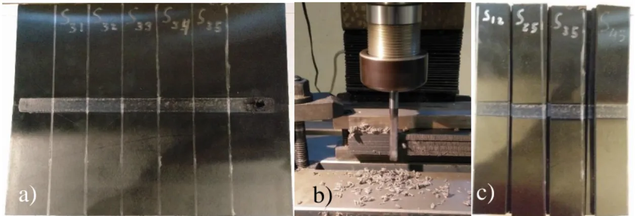
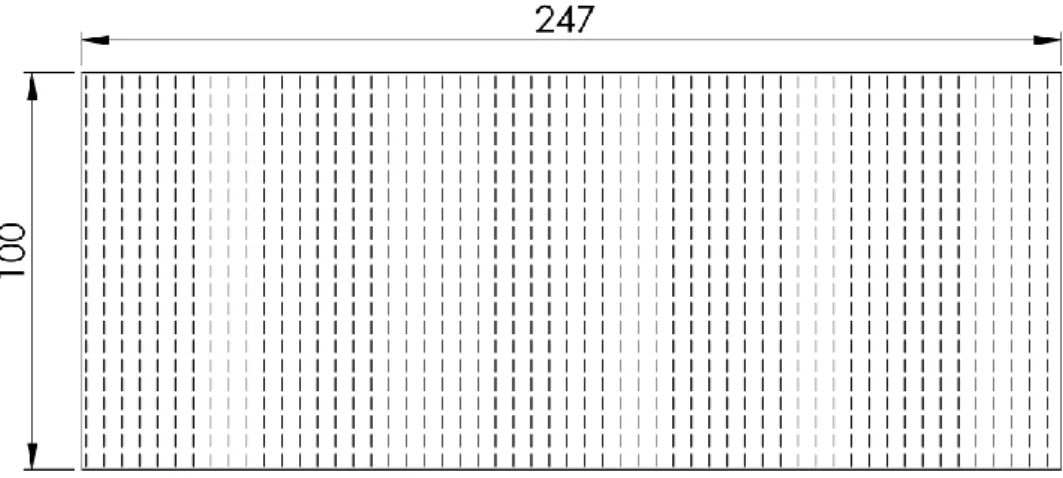
Figure 48 - Specimens dimensions. ... 41
Figure 49 - a) Plates with markings b) machining of the specimens and b) final specimens .. 41
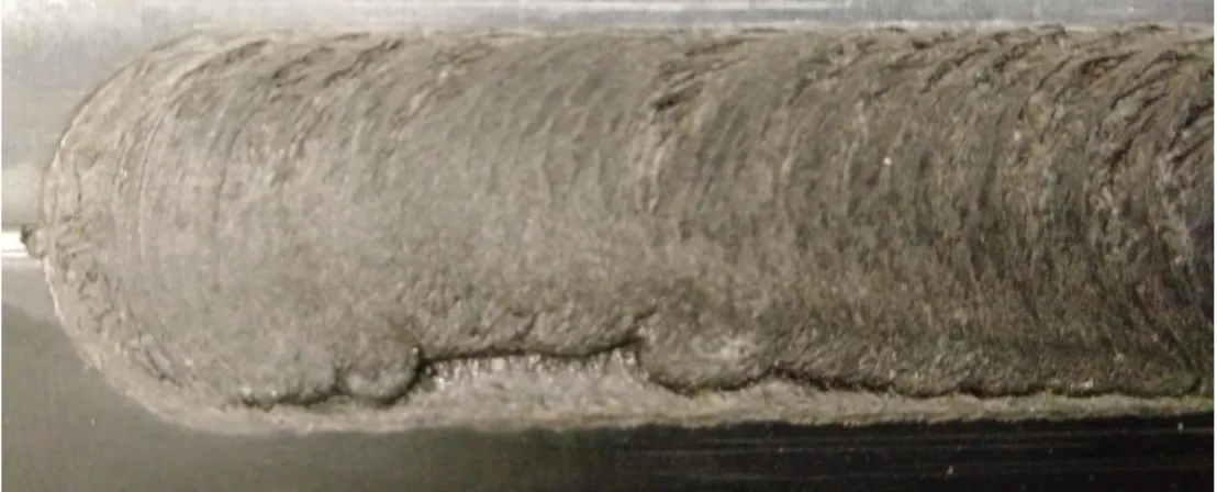
Figure 50 - Specimens weld view from the side ... 41
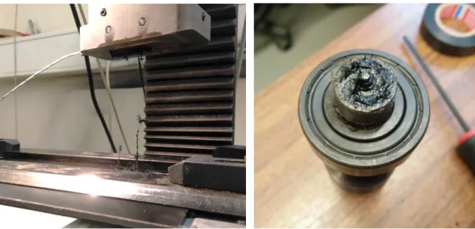
Figure 51 - Tensile test of specimen ... 42
Figure 52 - Bottom view of hybrid tool ... 43
Figure 53 - Welding with hybrid FSW tool (left) and resulting weld (right) ... 44
Figure 54 - Weld material stuck inside the tool, on the probe and on the shoulder face ... 44
Figure 55 - Welds obtained from hybrid tool (top) and weld from rotating shoulder tool (bottom) ... 45
Figure 56 - Defect in the retreating side and onion ring defect of the surface of weld. ... 45
Figure 57 - Temperature measurement for dwell time of 82 s with an axial force of 600 N and a rotation of 2000 rpm. ... 46
Figure 58 - Temperature measurement during dwell time without using composite material. 46 Figure 59 - Temperature measurement for tool heated with two soldering irons. ... 47
Figure 60 - Temperature measurement for tool heat with heat gun ... 47
Figure 61 - Temperature measurement for different heating procedures of the welding tool. . 48
Figure 62 - Weld from hybrid tool preheated to 150 ºC, a) top view, b) bottom view. ... 49
Figure 63 - Middle section of weld produced by hybrid tool preheated to 150 ºC ... 49
Figure 64 - End section of weld produced by hybrid tool preheated to 150 ºC ... 50
Figure 66 - Force measured during welding using hybrid tool preheated to 150 ºC ... 51
Figure 67 - Weld from hybrid tool with protruding sleeve preheated to 270 ºC, a) top view, b) bottom view ... 52
Figure 68 - Temperature of the hybrid tool with protruding sleeve during heating to 270 ºC and welding ... 52
Figure 69 - Forces measured during welding using hybrid tool with protruding sleeve preheated to 270 ºC ... 53
Figure 70 - Weld from hybrid tool preheated to 269 ºC, a) top view, b) bottom view. ... 54
Figure 71 - Weld material stuck to the bottom of the welding tool... 54
Figure 72 - Temperature of the hybrid tool during welding. ... 55
Figure 73 - Forces measured during welding using hybrid tool preheated to 269 ºC ... 55
Figure 74 - True stress-strain curves of specimens H1 to H5 ... 56
Figure 75 - Specimens H4 a) fractured section, b) front view, c) top view and d) back view . 57 Figure 76 - Root defect of specimen H4... 57
Figure 77 - Broken specimen H3 on the advancing side (left) and on the retreating side (right). ... 58
Figure 78 - Fractured specimens H1 to H5 top view (left) and bottom view (right). ... 58
Figure 79 - Weld from PEEK stationary tool first attempt, a) top view, b) bottom view. ... 59
Figure 80 - Temperature of the PEEK stationary shoulder tool during welding ... 60
Figure 81 - Forces measured during welding using PEEK stationary tool. ... 60
Figure 82 - Weld from PEEK stationary tool second attempt, a) top view, b) bottom view. .. 61
Figure 83 - Temperature of the PEEK stationary shoulder tool during welding, second attempt. ... 61
Figure 84 - Forces measured during welding using PEEK stationary tool, second attempt. ... 62
Figure 85 - Load displacement curve for specimens S11 to S15 ... 63
Figure 86 - Load displacement curves for specimens S21 to S25 ... 63
Figure 87 - Load displacement curve for specimens S31 to S35 ... 64
Figure 88 - Load displacement curve for specimens S41 to S45 ... 64
Figure 89 - Load displacement curve for the highest load of each treatment condition ... 65
Figure 90 - Main effects plot for Means ... 66
Figure 91 - Main effects plot for SN ratios ... 66
Figure 92 - Fracture of highest load specimen, S23, from the advancing side (left) and the retreating side (right). ... 67
Figure 93 - Fracture of lowest load specimen, S11, from the advancing side (left) and the retreating side (right). ... 67
Figure 94 - Comparison of fractures from the root side of a) specimen S21 and b) S11. ... 67
Figure 95 - Fractures of specimens a) S11 to S15, b) S21 to S25, c) S31 to S35 and d) S41 to S45. ... 68
Figure 97 - Bending of specimen ... 69 Figure 98 - Force measured during welding of confirmation test. ... 70 Figure 99 - Side view of welds of the confirmation test ... 70
List of tables
Table 1 - Reinforcement classification [1] ... 5
Table 2 - Mechanical properties of different fibres [19] ... 5
Table 3 - Conventional FS welding of composites... 22
Table 4 - Stationary shoulder FS welding of composites ... 24
Table 5 - Selected properties of Durethan BKV 30 H2.0 901510 [62] ... 27
Table 6 - UTS of the base material ... 28
Table 7 - UTS of the base material ... 29
Table 8 - Main dimensions of the hybrid tool ... 35
Table 9 - Main dimensions for polymer welding tool ... 36
Table 10 - Level values for welding parameters ... 40
Table 11 - Constant parameters ... 40
Table 12 - L4 orthogonal array for three parameters with two levels each ... 40
Table 13 - Parameters used for FSW with non-heated hybrid tool. ... 43
Table 14 - Welding parameters for non-heated rotating shoulder tool... 44
Table 15 - Welding parameters for hybrid tool preheated to 150 ºC... 48
Table 16 - Welding parameters for hybrid tool preheated to 270 ºC with protruding sleeve... 51
Table 17 - Welding parameters for hybrid tool preheated to 269 ºC... 53
Table 18 - Ultimate tensile strength obtained from hybrid tool heated to 269ºC ... 55
Table 19 - Welding parameters for PEEK stationary shoulder tool, first attempt... 59
Table 20 - Welding parameters for PEEK stationary shoulder tool, second attempt. ... 61
Table 21 - Ultimate tensile strength obtained from tensile tests ... 62
Table 22 - Maximum load obtained from tensile tests ... 62
Table 23 - Analysis of variance for UTS ... 65
1 Introduction
Organic matrix composites originated in the World War II as a way to produce materials with higher specific strength and stiffness for aerospace application and, in more recent years, they have expanded to diverse areas. In the sports and recreation market, composites are used in golf clubs, tennis rackets, bicycles and so on. In the automobile industry, the utilization of composites makes it possible to achieve more energy-efficient vehicles through weight reduction [1].
Polymer composites offer a wider design freedom than traditional materials, such as metal or wood. Parts can be made larger, permitting the reduction of joints and consequently reduction of assemblage costs. Aesthetically polymers are very versatile, being able to resemble other materials, also they can be transparent or opaque, coloured and decorated [2].
Thermoplastics have lower density and lower energy consumption during processing, compared to metals. When compared to thermosets, thermoplastics have shorter processing times, higher toughness, the ability to be welded and are easier to recycle [3].
Thermoplastic composites have been used in aeronautical applications, some of them include the wing leading edge of the Airbus A380, the horizontal tail plane of the Leonardo AW169 helicopter and the rudders and elevators of the Gulfstream and Dassault business jets [4]. It is an interesting material group for space structures because of their low moisture absorption and low outgassing which reduce problems related to moisture swelling [5]. According to Effing [6], short fibre reinforced thermoplastics represent the 48% of the European composite market, making it the largest market segment, as can be seen in Figure 1.
Friction stir welding (FSW) has been used in several industrial applications, for example in the welding of the Audi R8 Spyder B pillar [7]. Initially developed to weld hardly weldable metal alloys like 2000- and 7000-series aluminium alloys, FSW presents several advantages [8, 9]:
• Lower energy consumption than other welding processes; • Absence of filler materials;
• Absence of toxic fumes;
• Ability to weld dissimilar material;
• Ability to be used in different joint configurations.
More recently, it has been investigated its usage when welding polymers, but there are still few studies about friction stir welding of composites.
The demand for lightweight structures and vehicles, as well as a higher awareness about environmental issues make the usage of FSW and thermoplastic matrix composites an attractive option to achieve more environmentally friendly and energy efficient solutions. The increase in usage of thermoplastic composites demands the development of joining techniques that provide better efficiency, fast joining times and easy automation. Friction stir welding may be an alternative to achieve these goals.
The welding of composites in this thesis was executed in INEGI’s Optics and Experimental Mechanics Laboratory (LOME).
1.1 Project goals
The goal of this thesis is to study the weldability of composites by friction stir welding. For this purpose, a literature review was made in order to identify the type of composites with wide industry usage more suitable for friction stir welding and to identify the main features necessary to design a suitable tool for composites welding.
1.2 Structure of the thesis
The structure of the thesis is presented below and is constituted by 6 different chapters.
Chapter 1 - Introduction to the thesis, presenting the motivation for the work and the topics discussed in the present work.
Chapter 2 - Literature review about composites and composite joining. First, an introduction to composites is given, followed by a description of alternatives to join thermoplastic composites.
Chapter 3 - Literature review on FSW of composites regarding different materials, tool designs and most influential parameters.
Chapter 4 - Experimental details, such as the material used, tools used, design of experiments and testing procedures are described in this chapter.
Chapter 5 - This chapter regards the experimental results of the temperatures and forces during welding when using different weld tools, different preheating temperatures and the results of design of experiment using an L4 matrix being the response the UTS of the specimens obtain
through tensile tests.
2 Thermoplastic Composites
According to Bootle, et al. [10] composite materials are the combination of two or more distinct materials at a macroscopic level having a recognizable interface between them, usually they consist of a reinforcement material such as fibres or particles supported by a binder (matrix) material. In the automotive industry thermoplastic matrix reinforced with randomly oriented short (typically less than 1 mm long) E-glass fibres are used in parts like air intake manifolds, water pump housings and gears in the door window mechanism, while thermoplastics reinforced with unidirectional or bi-directional continuous fibres can be found in seat structures, bumper beams and cross members [3].
Composite materials are becoming more prominent due to their low weight and other unique features, an example of this is that the Boeing aircraft, 777 Dreamliner had 12% components manufactured from composite while the more recent aircraft, 787 Dreamliner contains 50% components manufactured from composites [11]. Composites are commonly classified at two distinct levels: the matrix constituent and the reinforcement form [1].
2.1 Matrix
The major composite matrix classes are metal matrix, ceramic matrix and organic matrix. This last one can be further divided into polymer matrix and carbon matrix [1]. In this work an emphasis will be given to polymer matrix composites, in particular thermoplastic composites. According to the Oxford Dictionary of Biochemistry and Molecular Biology (2nd Edition) [12] a polymer is “any substance that is composed of molecules containing a large number of constitutional units (or ‘mers’) that are in repetitive covalent linkage and that maybe of one or more than one species. Polymers are generally considered to comprise at least ten mers, although sometimes the term is taken to imply simply ‘more than one’ mer.”
In terms of polymers these can be divided in to thermoplastic and thermosetting. Thermoset plastics are network polymers, they have covalent crosslinks between adjacent molecular chains, whereas thermoplastic the adjacent molecules are affected mainly by secondary forces [13].
The advantage of thermoplastics over thermosetting polymer is that latter one resists deformation and heat softening and thus cannot be reprocessed. To join thermosetting polymers it must be used either mechanical fastening or adhesive bonding since welding methods cannot be applied [11]. Thermoplastics are high-molecular weight polymers that can be reheated, which causes a weakening of secondary van der Waals or hydrogen bonding forces enabling welding operations, also their processing time is significantly lower than thermosets [3, 14]. Although they can be processed repeatedly, this will cause deterioration of some of their properties [3].
Polymers can be categorized in relation to their crystallinity. Crystallinity refers to the molecular arrangement which produces an ordered atomic array, if there is no repeating structure then the polymer is amorphous. As a result of their size and complexity polymers are
usually semi-crystalline, this is, they have crystalline regions disperse in an amorphous region, as can be seen in Figure 2 [13].
Figure 2 - Arrangement of molecules in (a) amorphous polymers and (b) semi crystalline polymers [15].
Crystalline thermoplastics are tough, soft and translucent to opaque, they are used in structural applications, compared to amorphous thermoplastics they have good wear resistance, high chemical resistance, high coefficient of thermal expansion and low coefficient of friction, but low impact resistance. Some of these polymers are polyethylene and polypropylene [11]. To be welded they have to be heated above their melting temperature [16].
Amorphous thermoplastics are hard, rigid and clear, they soften over a range of temperature and are easy to thermoform. They have good impact resistance and their structure consists of randomly oriented and tangled molecules. Some of these polymers are polycarbonate and acrylonitrile butadiene styrene [11]. To be welded they must be heated above their glass transition temperature [16].
Semi crystalline uncross-linked polymers behaviour depends on how they are solicitated, higher rate of deformation reduces the loading time, causing stress increment to reach higher levels, also the relaxation of molecular chains makes the deformation time dependent [17].
The incorporation of fibres into a thermoplastic resin is much harder than in a thermosetting resin, because of their higher viscosity, making it difficult to get good fibre wet-out, although Arkema provides a liquid thermoplastic, Elium®, that can be processed like a thermoset and is suitable to be used with RTM, a technology normally only appropriate for thermosetting resins [18]. Thermoplastic prepregs can be stored for unlimited time without any special storage facility, and are produced by hot melt impregnation, solution impregnation, liquid impregnation, film staking, fibre mixing and dry powder coating [15].
2.2 Reinforcement
The reinforcements can be particulates, whiskers, continuous fibres and woven composites, they are classified in Table 1. In order to provide a useful increment in proprieties, usually 10% or more volume of reinforcement is required. There are materials that contain particles, not for the purpose of reinforcements, but for cost reduction they are generally referred as “filled” systems rather than composites [1].
Table 1 - Reinforcement classification [1]
Reinforcement Description Type
Particle All dimensions are roughly the same Discontinuous Whisker Aspect ratios between 20 to 100 Discontinuous Short fibre Have length much greater than their cross-sectional
dimensions
An increment in fibre length translates in an increment of the composite proprieties
Discontinuous
Continuous fibre
Have lengths much greater than their cross-sectional dimensions
An increment in fibre length doesn´t translates in an increment of the composite proprieties
Continuous
Woven Interlocking fibres that have orientations slightly or fully in an orientation orthogonal to the primary structural plane
Continuous
The most common fibre reinforcements are glass fibres, aramid fibres and carbon fibres. Glass fibres represent an estimated 95% of consumption while the remaining 5% is mostly accounted by carbon and aramid fibres. The practical goals of fibre reinforcement are to increase modulus and strength, improve heat deflection temperature, reduce tendency to creep and in some cases to save costs [19].
The most common types of Glass fibres are E-glass and S-glass. They are used due to their low cost, high tensile strength, high chemical resistance and insulating properties, but suffer from low tensile modulus, high density, sensitivity to abrasion during handling, low fatigue resistance and higher tool wear. Carbon fibres have exceptionally high tensile strength, high tensile modulus, low coefficient of linear thermal expansion, high fatigue strength, high thermal conductivity, but they have high cost, low strain to failure and low impact resistance. Aramid fibres are highly crystalline aromatic polyamide fibres that have the highest tensile strength to weight ratio, are resistant to impact damage and have low coefficient of thermal expansion, but they are difficult to cut or machine and have the lowest compressive strength [15]. Table 2 compares the mechanical properties of the three previously mentioned fibres.
Table 2 - Mechanical properties of different fibres [19]
Fibre Properties E-glass Aramid Carbon
Density [g/cm3] 2.6 1.44 1.7-2
Tensile strength [MPa] 2000-3500 2900-3000 2000-6400
Tensile Modulus [GPa] 70-73 70-130 200-590
2.3 Fabrication processes
The incorporation of fibres into the matrix can be divided into two separate groups: one in which the fibres and the matrix are processed simultaneously into the finished product and the other where fibres are incorporated into the matrix to prepare ready-to-mould sheets [15].
2.3.1 Injection moulding
Parts made of thermoplastic composite reinforced with short fibres up to 10 mm may be produced through conventional injection moulding, that consists in forcing melted thermoplastic into a mould cavity and then cooling it down under pressure. The injection machine comprises of an extruder with heating device, a ram system, to allow filling of the mould cavity and application of pressure, and a cooling device to cool down the mould and the part allowing to a faster solidification and release of the part, an can be seen in Figure 3 [20].
Figure 3 - Injection moulding machine [3]
Parts with fibres longer than 20 mm cannot be processed on conventional injection, but they may be processed with compression moulding or extrusion-compression technique. Compression moulding consist in using composite sheets or chopped unidirectional tapes that are compressed by a hot mould and when the composite is softened and shaped the mould is cooled and the part demoulded. Extrusion-compression consists in heating the composite and extruding it with a screw extruding machine that feeds a compression mould, the composite is then compressed and the part is obtained [20].
2.3.2 Prepreg
A prepreg is a fibre layer pre-impregnated with a polymer, these layers can be stacked to produce a laminated composite [3]. Prepregs of thermoplastic can be produced by[15].
• Hot melting process: mainly used for semi crystalline thermoplastics and consists in pulling collimated fibre tows through a die that delivers a fine sheet of hot polymer melt under high pressure.
• Solution impregnation: only suitable for polymers that can be dissolved in an adequate solvent and consists in dissolving the polymer in the solvent and using the mixture to impregnate the fibres, afterwards the material is heated to remove the solvent, for this reason low boiling point solvents are preferred.
• Film stacking: consists in using woven fabrics or random fibre mats between sheets of unreinforced thermoplastic polymer, the layers are pressed together and heated to force the thermoplastic into the reinforcement layer.
• Fibre mixing: a process where fibres of reinforcement and filaments of thermoplastic are mixed by commingling, wrapping or co-weaving. During the moulding stage the thermoplastic fibres are melted and spread to wet the reinforcement fibres.
• Dry powder coating: a process that charges and fluidizes thermoplastic powder in order to coat the reinforcement fibres. The fibres are then heated, and the polymer coating is melted on the fibre surface.
To produce a laminated thermoplastic composite, stacks of several layers of continuous fibre prepregs or bi-directional fabric prepregs are heated and then pressed. The fibre orientation can be different in each layer, as can be seen in Figure 4, giving more design flexibility [3].
Figure 4 - Example of laminate made from differently oriented layers [3]
Most laminated composites are orthotropic. They have properties that are different in three mutually perpendicular directions. a load applied parallel to these axes produces only normal strains and loads not parallel to the axes produce normal and shear strains [21].
2.4 Joining
In plastic product design, as well as in composite materials, the ideal situation is to a have one piece item, but manufacturing limitation may make necessary to use joining operations [14]. Plastic joining can be categorized as fastening, bonding and welding procedures. Fastening uses an external body to produce the joint, bonding uses a solvent or an adhesive to join the parts and welding is a procedure where the parts are fused together. Figure 5 displays and categorizes different plastic joining procedures.
Figure 5 - Various plastic joining processes [22]
2.4.1 Adhesive bonding
In a general way, adhesive bonding consists in the application of an adhesive (usually a polymeric material) to a substrate and holding the components together while the adhesive cures. The main mechanisms which allow the joining to occur are: adsorptive, electrostatic and diffusive [23].
Adsorptive forces result from intimate interaction between particles at the joint surface. The attachment can be through weak, dipolar or van der Waals interactions or through chemical bonds. Electrostatic forces are a result of ionic bonds between oppositely charged species or molecules. Diffusive forces are consequence of molecular chain entanglement between the substrate and the adhesive as they diffuse through the joint interface [23].
Adhesives can be classified as a one-part system or two-part system. One-part systems don’t require mixing or stirring before usage, with the curing times ranging from seconds to hours depending on the adhesive. Two-part adhesives rely in the mixing of two components in specific proportions [22].
There is a limit to how long an adhesive can be stored, this limit is denominated as shelf life and can varies from a few days to over a year depending on storage conditions and adhesive. In general, two-part adhesive systems have longer shelf life, but after mixed they have a limited time to be applied, this time is the pot life. After the joint has been made, there is a cure time required to achieve the best mechanical properties of the joint, this time depends on the ambient conditions and the adhesive [24].
Structural adhesives are adhesives that can support high proportion of its maximum failing load for long periods without failure. The most used adhesive groups are epoxies, polyurethanes, modified acrylics, cyanoacrylates and anaerobics [24].
Adhesive bonding of thermoplastics usually results in lower bond strengths when compared to thermosets. Thermoplastics have inert, nonpolar surfaces that make it difficult for the adhesive
to wet the surface and thus surface preparations such as sodium hydroxide etching, grit blasting, acid etching, plasma treatments, silane coupling agents, corona discharge or aramid peel plies must be employed to improve adhesion [14].
Joint design is important to ensure that the adhesive is loaded in shear, since bonded joint that are subjected to peel or cleavage are less efficient. If peel forces cannot be avoided, a ductile adhesive should be used. Double strap joints and scarf joints may perform better than single lap joints, but they are more time consuming and difficult to produce, so single lap joints remain one of the most used configurations for adhesive bonding [24]. Different joint designs can be seen in Figure 6.
Figure 6 - Joint designs for adhesive bonding adapted from [23]
Adhesive bonding is a common procedure when regarding composite joining. It allows for a continuous connection avoiding large stress concentrations when compared to mechanical fastening, bonded joints are usually lighter than mechanically fastened joints and, in some applications, less expensive, also dissimilar material can be joined together.
However there are disadvantages when using adhesives which are the necessity of a clean surface, the application of a surface treatment in order to increase surface energy and thus wetting, the requirement of long curing times, the strength of the bond is highly affected by the physical and chemical actions of the environment, thermosetting adhesive bonding is harder to recycle, it is difficult to assess the joint strength without destructive tests and joints are permanent [24, 25].
2.4.2 Mechanical fastening
Fastening refers to the introduction of a foreign body to join mechanically two different parts. This process is suitable for joining similar and dissimilar materials. Some examples of fasteners are screws, rivets, bolts, snap-fits, brackets, clamps and staples. It’s one of the simplest solutions for joining different components and can be divided into two categories: permanent fasteners and permanent fasteners. Permanent fasteners are more robust and economical but non-permanent fasteners are easier to disassemble and replace [16, 22]. Figure 7 shows some of the fasteners available for thermoplastics.
Figure 7 - Different mechanical fasteners for thermoplastics
Mechanical fastening is an option when regarding the joining of composite materials. However, some typical problems from fastening are stress concentration due to the presence of holes and cut-outs, delamination originating from the localized wear occurring during drilling, also the hole drilling process is time consuming, differential thermal expansion of the fasteners relative to the base material, possible galvanic corrosion at fastened joints, additional weight to the structure, development of stresses with the passage of time and difficulty in having a leak proof seal [11, 25].
Friction riveting
Friction riveting is a relatively new variant of mechanical fastening technique suitable for joining polymers to metals, or polymers to polymers, patented by Amancio Filho, et al. [26]. It consists in the insertion of a metallic rivet that deforms inside the polymeric material to be joined. Firstly, the material to be welded is firmly fixed. Then, a rotating rivet descends into the material to be joined generating heat through friction, and when pre-set friction time is reached the rotation stops and forging pressure is applied up to the end of the joining time. Figure 8 exemplifies the process [27].
Figure 8 - Schematic of friction riveting process A) Positioning and clamping of joining partners, B) Insertion of rotating rivet into the polymeric base plate, C) Rotation braking and subsequently rivet forging, D) Cooling and
joint consolidation. [27]
Mechanical Fastening
Non permanent
Screws
Bolts
Nuts
Permanent
Snap-fits
Inserts
Staking
Rivets
The rivet deforms inside the polymer due to the low thermal conductivity of the polymer which makes possible to achieve temperatures high enough to plasticize the rivet and soften the tip. The process can be decomposed into distinct phases.
Firstly, the friction regime is solid state, but when the polymers achieves the softening point (for amorphous polymers it’s when the glass transition temperature is reached and for semi-crystalline it’s when the melting point is reached), the friction regime changes to molten state beginning an unsteady state of viscous dissipation.
Another phase is after it reaches a steady state of viscous dissipation, then starts the phase where the rivet is forged. This is when the rotation is stopped, and it is pushed into the material which causes a deformation that results in a paraboloidal shape of the rivet and produces flash from the squeezed polymer.
Finally, the joint cools down under constant pressure, this is the consolidation phase, the molten polymer consolidates around the rivet creating a joint obtained by mechanical interference and enhanced by polymer-metal adhesion [27].
Gagliardi, et al. [28] studied friction riveting of two PA6 plates with and without glass fibre reinforcement and concluded that the strength of the joint was very dependent of the spindle speed. The reinforced polymer formed a stronger joint compared to the unreinforced polymer. The forging pressure is mainly dependent on the rivet stroke, if the rivet stroke increases the forging pressure increases. The temperature is affected mainly by the linear velocity during plunging of the rivet during the friction phase.
The advantages of this procedure is the ability to join dissimilar materials, such as plastic to metal, no surface treatment is required, disassembly of components for inspection and repair is relatively simple, and the integrity of the joint can be predicted [11, 14].
2.4.3 Welding
Welding is an establish technology in the thermoplastic industry where the welded joint can approach the properties of the bulk material. It has reduced processing times and less surface preparation compared to other methods, but it may induce residual stresses, the presence of carbon fibres imposes difficulties such as uneven heating, delamination and distortion of the laminates due to the increase of thermal and electric conductivity. Moreover, a high percentage of fibre reinforcement makes it more difficult to weld because of the reduction of matrix available to melt and reconsolidate [25].
Kiss, et al. [29] studied the welding of neat PLA and basalt fibre-reinforced PLA by laser, ultrasonic, hot gas and friction stir welding and concluded that, even though the joint efficiency on the composite was much lower, the joined material with fibres had higher strength than the joined material without fibres for all welding methods.
Fiebig and Schoeppner [30] analysed the influence of the initial fibre orientation when welding by hot plate and vibration. They concluded that for short fibres there is no advantage in orientating the fibres since the squeeze flow has too much influence in the final orientation of the fibres of the welded specimens. In contrast for long fibres, having more fibres initially orientated perpendicular to the weld seam results in better results when using hot plate welding, but not with vibration welding. Further studies need to be made in other to assess if these conclusions are applicable to FSW.
It is possible to join different polymeric material if their viscosity and their melt flow index (MFI) are similar enough. This condition makes it possible for strong mixing between the two. In order to approximate the MFI of the materials, particle reinforcements may be added to the polymers [31].
Compared to metals, the heat requirement of thermoplastics is less, but they are more sensitive to it, making the welding temperature range more restrictive. Excessive heat input will cause material degradation and insufficient heat input will produce defective joints [31].
Hot Tool Welding
Hot tool welding or hot plate welding consists in putting the parts to be welded in contact with a heated tool until a soften layer is created. The tool is removed, and the parts are pressed together until the molten layers consolidate, as schematically shown in Figure 9. The main parameters of this process are the tool temperature, the pieces preparation, the welding time, the thickness of the molten material and the weld penetration. The shorter the welding penetration, the higher is the weld strength for different meltdown thicknesses [32, 33].
Figure 9 - Schematic of the hot-tool welding [33]
The advantages of this process are ease of assembly, no need for filler materials, ability to embed parts between the two joining pieces, freedom of shape, high production rates and the ability to produce hermetic seals. The disadvantages are the high energy consumption, expensive tool equipment, required cleaning of the welding tool, presence of residual stresses and a slow start up, this is, the required time to heat up the tool is high [32].
Gehde, et al. [34] studied hot tool welding of glass mat reinforced thermoplastic (GMT) of polypropylene and polyamide matrices, glass fibre reinforced with average fibre length of 30 mm and with fibre mass content of 25% for the PP and 35% for the PA The molten layer does not affect much the strength of the weld, but the weld penetration does. Higher weld penetration (joining length) translates into lower weld strength. A thicker molten layer makes it easier to get good results for different joining lengths. The joint efficiency was of 0.42 for the PP GMT and 0.4 for the PA GMT and the highest weld strength was similar to the strength of unreinforced base material.
Kagan [35] studied several materials and welding methods, one of which was PA 6 reinforced with 33% short glass fibres welded using hot plate welding. The joint efficiency obtained was 48%, corresponding to a strength increment of 12% relative to the unreinforced base material.
Induction Welding
Induction welding consists in the utilization of an induction coil that when passed with alternating current creates a time variable magnetic field that induces eddy currents in the electrically conductive material in the vicinities. The induced currents are met with resistance from the material and energy is lost in the form of heat, for this to work the material must be electrically conductive or have a susceptor between the parts [36].
The equipment consists in a radio frequency power generator, a heat station which includes the induction coil, the material to be welded and secondary equipment such as cooling system. It is important that the distance between the coil and the part is as small as possible in order to assure maximum energy transfer, also the coil needs to be designed to avoid magnetic field cancellation. The main parameters of this process are the current frequency, input power, pressure between the parts, welding time and cooling time [36].
There are different geometries for induction coils, some of them are single turn, solenoid coil and pancake, illustrated in Figure 10. Single turn coils concentrate the magnetic field around the diameter and is used mainly in circular areas. Solenoid coils are bigger versions of single turn ones and are able to heat larger cylindrical areas within its centre. Pancake coils can heat large flat areas and using then in both sides of the welding zone creates more uniform heating and thus better results [36].
Figure 10 -Different types of coils, (a) single turn (b) solenoid (C) pancake [36]
If the fibres are not electrically conductive, for example aramid and glass fibres, then an insert must be used as a magnetic susceptor. The advantages of using a susceptor are a more precise location of the heat and the ability to weld nonconductive composites, but the addition of an insert raises weight, requires good bonding between it and the composite and it could act as a contaminate inducing residual stresses or causing stress concentration [23, 36].
The advantages of this process are high production rates, hermetic seals, joints with high strength, precise heating control, welding of large parts with bond lines up to 6 m, welding of joints with complex three-dimensional shapes and no surface treatment is needed. The disadvantages are complicated assembly operations, expensive machinery, the magnetic field may heat unintended elements around it that are not insulated and the edge effect, which causes uneven heating [23, 32, 36].
Resistance Welding
Resistance welding consists in using a metallic heating element between the parts that will be welded, it will remain embedded in the joint after welding is finished, Figure 11 exemplifies the process, also it’s one of the most utilized welding techniques for composites.
The metallic insert is heated through the Joule heating affect and currents as high as 150 A may be applied, in order to achieve temperatures higher than the materials melting point. It is important to maintain pressure between the parts during welding and cooldown, in order to prevent deconsolidation due to fibre bed relaxation [14, 32]. The Airbus A380 has the ribs welded to the skin of the wings leading edge through this method, another application is in the joining of car bumpers and panels [14, 26].
Figure 11 - Schematic of resistance welding [32]
The advantages of this technique are easy workability, joint design flexibility, ability to disassemble through the heating of the insert, reduced risk of air contamination and inexpensive equipment. The disadvantages of this procedure are the high skill required from the operator, long welding times, the mandatory use of a resistance element, which also results in harder recycling of the component and the resistance must be insulated from any conductive constituents making the introduction of a neat resin film as an interlayer beneficial due to better thermal and electrical isolation and helping the diffusion process by creating a resin rich region [25, 32].
Ultrasonic Welding
Ultrasonic welding produces good results in the joining of composites. It consists in subjecting the workpiece to ultrasonic vibrations (usually from 20 to 40 kHz) using a sonotrode which produces heat that can be selectively generated at the joint interface. For this to happen, the surface should have asperities that concentrate and dissipate heat, Figure 12 exemplifies the equipment [25]. The weldability is basically determined by the rigidity of the material, the greater the stiffness the better the weldability will be [32].
Figure 12 - Schematic of ultrasonic welding [37]
The advantages are that it is easily automated, fast, economical, consistent, absence of filler material and energy efficient [23, 25, 32].
The disadvantages of ultrasonic welding are the introduction energy directors (man-made asperities) and consequent fibre disruption at the interface, the impossibility to weld large joints in a single operation. Tooling costs for fixtures can be high, specifically designed details are required, noise concerns, at 40% filler content, fibres accumulate at the joint interface, and insufficient thermoplastic material is present to form a strong bond, highly plasticized materials such as vinyl are poor conductors of ultrasonic energy making them very hard to weld and it may cause damage to electrical components [23, 25].
Laser Welding
This welding process consists in the application of a laser beam to heat and melt the joint area. It’s well suited to deliver controlled amounts of energy to a precise location due to the ease of controlling the laser beam size and the available range of methods for positioning and moving the beam. When the laser strikes the polymer it may be transmitted, reflected or absorbed. The type of material, additive content, surface coatings, laser wavelength, intensity and movement affect the radiation absorption [23].
There are two types of laser welding: absorptive and transmitted. Absorptive uses a CO2 laser,
but due to the limited radiation penetration it is limited to thin sections. Transmitted laser welding, exemplified in Figure 13, uses YAG laser and it requires that one of the welding pieces is transparent to the laser radiation while the other piece observes it. This technique allows for thicker pieces to be welded [23, 32].
Figure 13 - Transmission laser welding [23]
Laser welding has the advantage of the absence of generated particulates, smooth flash, fast weld cycles, low amount of residual stress, well defined heat affected zone, possible to automate, no vibrations, suitable for high melting point polymers and no contact with heated tools. However it suffers from high equipment cost, limited weldable materials and geometries, joint surfaces must be of good quality, part clamping is necessary to ensure contact during welding and thickness limitations especially in highly crystalline materials [23, 32].
3 Friction Stir Welding
Friction stir welding, invented at The Welding Institute (TWI) of UK in 1991, is a solid-state joining technique initially applied to difficult to weld aluminium alloys [38, 39]. Although it is a solid-state welding technique (welding occurs below the materials melting point) in the case of metallic material, it’s not fully solid-state in the case of polymers, due to the different molecular weights, they don’t have a particular melting point, but a melting range [40].
FSW consists in a non-consumable rotating tool that generates heat through friction with the material being welded. The tool can be decomposed into two main parts, the probe and the shoulder. The combination of the localized heating around the probe, the tool’s rotation and translation plasticizes and transports the parent material in the nugget zone. The material in the weld nugget moves from the front of the pin to the back of the pin, due to the rotation of the pin [16, 38]. Figure 14 exemplifies the FSW process. The weld can be divided into two sides: one in which the rotational direction matches the welding direction (advancing side), and one in which the rotational direction is opposite to the welding direction (retreating side) [9].
Figure 14 - Schematic of conventional FSW process [41]
The welding technique can be decomposed into tree distinct stages, plunging, traversing, and retracting as seen in Figure 15 [11].
Figure 15 - Stages during welding [11]
The process can be used in many joint configurations for metallic materials, as can be observed in Figure 16, but has been mostly used in the butt and lap configuration since its invention [11]. Most studies of FSW of polymers tend to use either the butt or lap configuration and only a few analyse the T lap joint configuration.
The butt joint configuration is more challenging to weld due to the torque of the tool, which causes lateral movement of the plates during the plunging stage, resulting in defects. To avoid this, careful clamping setup is required [9].
Figure 16 - Joint configurations for friction stir welding: (a) square butt, (b) edge butt, (c) T butt joint, (d) lap joint, (e) multiple lap joint, (f) T lap joint, and (g) fillet joint [38]
The advantages of this technique are its simplicity and energy efficiency when compared to ultrasonic wielding and laser welding, non-addition of weight during the welding process, the ability to join dissimilar materials, consistent weld quality and high productivity can be achieved through proper combination of materials, parameters and tool design [11].
FSW process variables can be divided into three groups, machine parameters, welding tool parameters and material properties. They are as followed [23, 42]:
• Machine parameters; o Axial force; o Dwell time; o Plunge depth; o Rotation speed (ω); o Tilt angle (α); o Travel speed (ν); • Welding tool parameters;
o Pin diameter; o Pin length; o Pin topology; o Shoulder design; • Material Properties; o Mechanical; o Thermal.
Some of the difficulties present in FSW are the high reactive forces required to keep the tool in the joint line, the necessity of a rigid clamping system and finding which parameters are better suited to weld the material. Some of the defects that may occur from this process are: keyhole defect, tunnel defect, flash defect, lack of filling, lack of mixing, root defect, voids in the retreating side, kissing bonds and material degradation [11, 42].
Flash defect occurs when soft material is overflows from the weld seam, accumulating at the top surface of the workpiece [42]. An example of flash defect is present in Figure 17.
Figure 17 - Example of flash defect and keyhole defect [40]
Tunnel defect is a result of improper mixing due to the material not reaching the plastic stage and, thus cannot be stirred causing a through inside cavity along the welding direction. It usually happens when the traverse rate is too high [11, 42]. This defect may also result from high rotational speeds due to excessive turbulence [43]. Increasing the plunge depth may help eliminate this problem [44]. An example is shown in Figure 18.
Figure 18 - Tunnel defect in stir zone [43]
Weld seam quality in the advancing side is better than on the retreating side, this may result from the lower temperature on the retreating side causing voids to form and poor material mixture [44, 45]. Simões and Rodrigues [46] FS welded PMMA and observed that the lack of transparency of the material was due to the formation of voids of its deeply non-homogeneous structure. This effect was more drastic in the retreating side of the weld as Figure 19 shows.
Figure 19 - Two (a) and three (b) dimensional images of PMMA weld [46].
The lack of length of the pin will result in lack of penetration and consequently the root side will not be bonded (root defect), as can be seen in Figure 20. On the other hand, if the pin is too long it will make the material from the root stick to the anvil [11]. The thickness of the root defect is roughly the difference between the probe length and the plate thickness, this can be eliminated using a double pass method [41].
Figure 20 - Root defect in weld [47]
The probe geometry in the FS welding of polymers needs to be threaded, otherwise proper mixing will not be achieved, visible in Figure 21, which results in lower strength of the welded joint [40].
One of the most important aspects in welding polymers is the heat input and temperature during the process. Banjare, et al. [48] obtained better surface quality and mechanical properties when FS welding PP with an external heat source and Vijendra and Sharma [49], got better results using an induction heated tool when welding HDPE.
3.1 Conventional Friction Stir Welding
Joining FRP using conventional welding processes causes the fibres to align parallel to the seam due to squeeze flow which results in reduced strength and introduces weak spots, but FSW causes material flow around the pin, this may have positive effect over the fibre orientation in the seam [45]. When using FSW, welding in the same direction as the fibre orientation may produce higher joint efficiency than welding in a perpendicular direction to the fibre orientation. It has been studied that the tool design has a big influence in the quality of the weld both in thermoplastics and composites with thermoplastic matrix. Ahmadi, et al. [50] concluded that the pin design has an important role in creating friction, heat and material flow, having obtained better results with a threaded cylindrical-conical pin, Figure 22, when lap welding two PP composites with 20% CF.
In another paper Ahmadi, et al. [51] studied the influence of welding speed, tilt angle and rotation speed of the pin, in the same material and configuration, having concluded that the most significant parameter was the travel speed and the least significant was the tilt angle. It should be noted that the tool used had a rotating shoulder.
Kumar, et al. [52] also studied the influence of tool rotation, travel speed and tilt angle, having concluded that the most significant parameter was tool rotation, followed by travel speed and tilt angle. The welded material was 30wt% glass filled Nylon 6 in a butt joint configuration. It was noted the highest tensile strength specimens presented a uniform microstructure at the weld and failed on the advancing side instead of the retreating side.
Figure 22 - Conventional FSW tool used by Ahmadi, et al. [51]
Kordestani, et al. [53] evaluated the effect of the pin design when FS welding two types of composites: PP composite plates reinforced with 30% GFs, with fibre lengths of 0.2-0.3 mm and PP composite plates reinforced with 30% CFs, with fibre lengths of 0.2-0.3 mm. The best results were achieved using a threaded tapered pin with a chamfer which resulted in a tensile strength of 30% relative to the base material in the case of the GF and 34% tensile strength relative to the base material for the CF composite.
Raza, et al. [17] studied the tool profile and particulate ceramic reinforcements in the FS welding of HDPE. He concluded that conical grooved pin with a concave shoulder gives better results compared with an unthreaded pin and to a plane shoulder. All of the reinforced material had a lower joint efficiency and ultimate strength than the welded plain HDPE, being SiC the particle reinforcement that provided best joint efficiency and graphite the most ductile behaviour. The SiC reinforced composite had the least variation of hardness across the weld nugget. The welding of composite via conventional FSW are summarized in Table 3.
Table 3 - Conventional FS welding of composites Base material Tool design ω [rpm] ν [mm/min] α [º] Efficiency factor [%] Ref. 30 wt.% glass filled Nylon 6 5 mm shoulder Ø18 mm cylindrical pin Ø6 mm stand-off 0.2 mm 600 12 2 42 [52] 30 wt.% CFR PP 5 mm shoulder Ø25 mm threaded-tapered pin with a chamfer Ø5 mm 2000 8 5 34 [53] 30 wt.% GFR PP 5 mm shoulder Ø25 mm threaded-tapered pin with a chamfer Ø5 mm 2000 8 5 30 [53] 30 wt.% GFR PP 5 mm shoulder Ø15 mm Taper pin with groove Ø5 mm
630 8 2 25 [43]
Depending on the base material and tool design, the most influential parameter is either the rotation speed or the travel speed, but the tilt angle is consistently the less influential for every tool and material. The effect of the axial force in the welding of composites lack study.
3.2 Stationary Shoulder Friction Stir Welding
The presence of a rotating shoulder in FS welding of thermoplastic and thermoplastic matrix composites results in bad surface quality and mechanical properties, due to the pushing of soft material out of the weld seam (flash defect). It causes material loss and, thus, poor joining, mainly in the retreating side of the weld [9, 54]. Stationary shoulder friction stir welding (SSFSW) was developed to weld low heat conductivity materials, where a more uniform heat input is beneficial [55].
A design that better suits the welding of polymers is the “hot shoe” design, shown in Figure 23. It consists in a static shoulder made of aluminium coated at the bottom with PTFE, in order to produce a smooth weld seam and preventing the sticking of the base material to the tool. The shoe is mainly responsible for trapping the soft material inside the weld bead and holding the weld under axial force while it cools down [9]. The primary source of heat is the friction between the rotating pin and the workpiece, but because many polymers tend to be self-lubricating at elevated temperatures and have low heat conduction, it may be required to provide external heat. This can be done by applying a thermocouple and heater to the shoe, or by using a hot backplate to heat the base material. This last method, although capable of creating very strong welds, has problems with repeatability [22, 41].
In order to reduce joint defects, it’s important to have a uniform cooling rate throughout the weld volume. If the outer material cools quicker than the inner material, a hard shell is formed and as the inner material cools down it contracts and pulls down from the shell causing the formation of voids [22].
Figure 23 - Hot shoe schematic (left) and picture (right) [56]
To avoid using external heating elements, Eslami [9] developed a tool consisting of a high performing thermoplastic material static shoulder, a rotating steel probe and a copper sleeve. The frictional heat generated between the copper sleeve and the rotating probe is enough to achieve quality welds with 97% strength of the base material, HMW-PE, in a butt joint configuration. Using this tool, rotational and traversing speeds are the most effective parameters regarding tensile strength of the welds, and it has good axial force stability when using position control.
Figure 24 - Static shoulder tool developed by Eslami [9]
Using a static shoe made of PTFE instead of a rotating shoulder, Czigány and Kiss [54] were able to produce butt welds with an efficiency factor of about 64% on a PP sheet reinforced with 30% glass fibres. The fibres in the seam were on average shorter than in the base material, this is due to the shearing forces evolving during the rotation of the tool. The FS welded glass fibre reinforced PP, when compared to FS welded PP sheets with no reinforcement, was found to have higher flexural strength which can be explained by the presence of the fibres in the seam. Laieghi, et al. [44] welded the polymeric nanocomposite composing of the combination of 80wt% polyamide 6 grafted with various percentages of halloysite nanotubes with 20% nitrile butadiene rubber. The tool used was a heated shoe design with the highest tensile strength being of 61 MPa, which is over 91% of the base materials strength. It was noted that insufficient heat resulted in rough surface as well as chip formation, material loss and fast solidification. In contrast by increasing the rotation of the pin and thus the thermal input, thermal degradation occurred due to polymer burning in the welding area which translates to a reduced weld strength.
Meyer, et al. [45], when welding polyamide 6 with 30% glass fibre in a butt joint configuration with a patented DeltaN tool that has a stationary shoulder, were able to obtain a tensile strength of 50 % the base material. A smaller shoulder diameter in combination with small tilt angles, low feed rates and high contact forces produced the best results. Lower feed rates lead to a higher energy input which lower the material viscosity and benefits the dynamics of the material
flow also improving the fibre presence and orientation in the seam. The fibre length in the seam was analysed, being observed that their size was reduced in 10 to 20%, but no correlation was found between the process parameters and fibre shortening, so the tensile strength was mainly influenced by processes parameters. The comparison of results for welding different composites using a stationary shoulder is shown in Table 4.
Table 4 - Stationary shoulder FS welding of composites
Base material Tool design ω [rpm] ν [mm/min] α [º] Efficiency factor [%] Ref. 80wt%PA6/HNT 20wt%NBR 5 mm hot shoe 30x160 mm threaded pin Ø5 mm 900 14 - 91 [44] 30wt% GFR PP 10 mm
Static PTFE shoulder 4-tooth milling cutter Ø8 mm
2100 - - 64 [54]
PA6-GF30 5.3 mm
Shoulder Ø20 mm threaded conical pin Ø6 mm
2000 25 2 50 [45]
3.3 Friction Stir Spot Welding
It is like FSW, but without the linear motion. The welding tool plunges into the base material under an axial force and after the desired temperature is achieved, by dwelling, it retracts as can be seen in Figure 25. The tool usually has a concave shoulder and a threaded pin. The anvil or backplate is used below the materials to be welded to counteract the axial force of the tool. The contact between the tool and the material produces heat by friction. When softened, the material is stirred and flows along the vertical direction along the pin’s threads. The tool displacement is continued until either a predetermined level of displacement or axial force is achieved, depending of the control mode of operation, after this, the rotation is kept for a specific dwell time and then retracted. This method was used in the welding of the Mazda RX-8 aluminium rear doors and hood [RX-8].
Figure 25 - Friction Stir Spot Welding process [8]
The advantages of this method are low energy consumption, cost efficiency and environmentally friendliness. Friction stir spot welding (FSSW) is limited to specific applications and geometries, also it requires an overlapped positioning of the joint [9].
3.3.1 Friction Spot Welding
There are some papers about a variant of FSSW, friction spot welding (FSpW), developed and patented by the Helmholtz Zentrum Geesthacht (HZG) research centre in Germany, used in composites [57]. Gonçalves, et al. [58] used friction spot welding to weld 2-mm-thick carbon fibre-reinforced polyamide 66 laminate with 49 vol% of fibres.
Friction spot welding distinguishes itself from friction stir spot welding, because it can avoid the formation of a keyhole defect by using a tool that consists of three distinct coaxial pieces: the clamping ring, the pin and the sleeve. The process can be seen in Figure 26 and consists in the fixation of the overlapped specimens by the clamping ring and the backing bar under constant pressure, after this the pin and sleeve rotate in the same direction at a pre-set speed and during a given friction time, followed by the plunging of the sleeve in to the specimen generating enough heat to soften or melt the polymer, simultaneously the pin retracts, creating a gap that is filled by the softened material, in the end the pin and sleeve return to their original positioning, by doing this the entrapped material in the gap is forced by the pin to refill the void left by the sleeve, after the weld cools down the tool can be retracted [58].
Figure 26 - Illustration of the FSpW process, showing the tool and the main steps [58]
3.4 Vertical reciprocating FSW
Vertical reciprocating FSW consists in a blade that reciprocates in the vertical direction, generating heat between the blade and the plastic material. The problem with this process is that there is no shoulder to maintain the molten material in the joint, as a result voids are created in the weld and strength is reduced. VibladeTM welding is a variant of the vertical reciprocating
FSW, in which the blade remains fully in the joint making it easier to contain the melt in the weld. The tool can be seen in Figure 27 and consists of a blade and a shoulder, that run along thermoplastic with a downward force, almost all the heat input is generated by the blade, since the top shoulder only melts material on top of the joint [23, 59].
![Figure 26 - Illustration of the FSpW process, showing the tool and the main steps [58]](https://thumb-eu.123doks.com/thumbv2/123dok_br/15718621.1070204/38.892.163.764.465.673/figure-illustration-fspw-process-showing-tool-main-steps.webp)


![Figure 46 - Maximum service temperature and thermal conductivity of different material groups [68]](https://thumb-eu.123doks.com/thumbv2/123dok_br/15718621.1070204/50.892.147.793.245.565/figure-maximum-service-temperature-thermal-conductivity-different-material.webp)