Universidade de Aveiro Ano 2016
Departamento de Engenharia de Materiais e Cerâmica
Elisa Cadete Quadros
Silva
Defect sources in brasses and new low lead
compositions
Universidade de Aveiro Ano 2016
Departamento de Engenharia de Materiais e Cerâmica
Elisa Cadete Quadros
Silva
Defect sources in brasses and new low lead
compositions
Relatório de estágio apresentado à Universidade de Aveiro para cumprimento dos requisitos necessários à obtenção do grau de Mestre em Ciência e Engenharia de Materiais, realizada sob a orientação científica do Professor Doutor Rui Ramos Ferreira e Silva, Professor Associado, coorientação do Doutor Filipe José Alves de Oliveira, Investigador Auxiliar, ambos do Departamento de Engenharia de Materiais e Cerâmica da Universidade de Aveiro e com supervisão empresarial por parte do Engenheiro João Fonte, Chefe do Departamento de Fundição da Grohe Portugal.
O júri
Presidente
Professor Doutor Augusto Luís Barros Lopes
Professor Auxiliar do Departamento de Engenharia de Materiais e Cerâmica da Universidade de Aveiro
Professor Doutor Victor Fernando Santos Neto
Professor Auxiliar Convidado do Departamento de Engenharia Mecânica da Universidade de Aveiro
Professor Doutor Rui Ramos Ferreira e Silva
Professor Associado do Departamento de Engenharia de Materiais e Cerâmica da Universidade de Aveiro
Agradecimentos Aos professores Rui Silva e Filipe Oliveira pelo auxílio no progresso deste trabalho. À Grohe Portugal, em especial ao Diretor de Produção João Fonte pelo favorável acolhimento e atenção despendida durante todo o tempo de estágio. Agradeço também aos meus familiares e amigos mais próximos.
palavras-chave Latão, baixo teor em chumbo, fundição, microestrutura, defeitos.
resumo Este estágio curricular foi realizado na empresa Grohe Portugal – Indústria de Componentes Sanitários S.A, localizada na zona industrial do Areeiro (Albergaria-a-Velha), distrito de Aveiro. A empresa Grohe foi fundada na Alemanha no século XX com o objetivo de produzir torneiras. Atualmente, a Grohe é reconhecida como a maior produtora de componentes sanitários da Europa, bem como pela qualidade dos seus processos produtivos e eficiência do sistema logístico e entrega de produtos.
A nível de processos produtivos, a Grohe está dividida em cinco departamentos: Fundição, Maquinagem, lixamento e polimento, Galvânica e Montagem. O departamento da Fundição, por sua vez, é constituído pela Fusão Central, Vazamento por Gravidade, Vazamento por Baixa Pressão e pela Macharia. Este trabalho teve como objetivos principais a caracterização microestrutural das três ligas de cobre de baixo teor de chumbo que a Grohe produz e identificação de possíveis origens dos defeitos mais comuns nestas ligas, sobretudo no Vazamento por Baixa Pressão. A Grohe prepara e controla quimicamente as suas próprias composições de latão num forno central de fusão, compostas maioritariamente por cobre e zinco (60% Cu, 40% Zn) e por pequenas adições de outros elementos de liga. Foi feita uma caracterização microstrutural às três ligas por microscopia ótica. Os materiais envolvidos no processo de vazamento como os revestimentos cerâmicos dos moldes, os filtros cerâmicos utilizados, a escória resultante do processo como também o tubo de vazamento constituinte da máquina de vazamento por baixa pressão foram submetidos a uma caracterização química por microscopia eletrónica de varrimento e difração de raios-X. Realizou-se uma análise química e microestrutural por SEM/EDS às inclusões presentes em sucata de torneiras de latão.
As microestruturas das três ligas fabricadas em Grohe apresentam diferenças significativas. O latão Grohe 0 com o menor teor de Zn e a menor quantidade de elementos afinadores de grão tem uma morfologia do tipo de Widmanstatten com placas grandes de fase α (97 μm x 17 μm) e a fase β presente entre os grãos de fase α. O latão Grohe 0 Light é uma liga hiperperitética com fase α na forma de agulhas finas (24 μm x 3 μm) no seio dos grãos-mãe β e ao longo dos seus limites de grão. A microestrutura da liga DZR consiste numa morfologia equiaxial mais fina (16 μm) de grãos de α numa matriz de β devido à maior quantidade de afinadores de grão e teor intermédio de Zn. O maior tamanho de grão do latão Grohe 0 explica por que este tem uma dureza menor (HRB 39) do que as ligas Grohe 0 Light e DZR (HRB 59), com microestruturas mais finas.
Os resultados da análise SEM/EDS aos defeitos da liga de latão Grohe 0 permitiram a sua divisão em quatro classes: (1) Defeitos ricos em Al, Si e O, tendo como possível origem o revestimento cerâmico BC11; (2) defeitos ricos em Al, Si, O e Pb, uma fase vítrea com origens no revestimento cerâmico ou em sucata reciclada; (3) defeitos ricos em Si e O, tendo como fontes prováveis a escória, partículas dos filtros cerâmicos ou sucata com restos de filtros cerâmicos, revestimento BC 15 ou mesmo areia dos machos; (4) defeitos ricos em Fe, Cr, V e Mo, muito provavelmente resultado de uma contaminação pontual com uma ferramenta fraturada usada para o processamento de matérias-primas.
keywords Brass, low lead, foundry, microstructure, defects.
abstract This work was done at Grohe Portugal – Sanitary Components S.A, located in the
industrial zone in Albergaria-a-Velha, district of Aveiro. This company was founded in Germany in the 20th century with the goal of manufacturing faucets for sanitary industries. At present time, Grohe is distinguished as the largest manufacturer of sanitary components in Europe, as well as by the quality in their productive processes and efficiency of their logistics system and product delivery. In terms of productive processes, Grohe has five departments: Foundry, Machining, Surface sanding and polishing, Galvanic and Assembly. In the foundry unit there is a central melting, sand core processing, two gravity casting units and six low pressure die casting machines. The copper-beryllium molds are manufactured in the company.
The work was based on the characterization of three low lead brass alloys that the industry produces and possible sources of defects. Since Grohe owns their own central melting station, where the manufactured brass is made primarily of copper and zinc (60% Cu, 40% Zn), the company does not buy previously fabricated brass for the casting process, this means there is total control of the content of the alloys.
Ultimately, this work aims in characterizing brass alloys at microstructural level, the presence of defects (pores or inclusions) and the study of the alloys that originate the larger amount of wastes.
A preliminary microstructural characterization was performed on the three brasses by optical microscopy. The materials involved during the processing of casting such as ceramic coatings, ceramic filters, produced slag, as well as the riser tube in the low-pressure die casting machine, were submitted to a chemical characterization by scanning electron microscopy and X-ray diffraction. A chemical analysis was performed by energy dispersive X-ray spectroscopy on specimens of inclusions detected in waste of brass faucets.
The microstructures of the three alloys manufactured in Grohe are markedly different. Grohe 0 brass with lowest Zn content and smallest amount of grain refining elements has a coarse Widmanstatten structure (97 µm length x 17 µm width) with the β phase present in the periphery of the plate-like α grains. Grohe 0 Light is a hyperperitectic alloy with a finer needle-like α phase (24 µm length x 3 µm width) inside the β mother grains and along their grain boundaries. The microstructure of the DZR composition consists of a finer equiaxed morphology (16 µm) of α grains in a β matrix due to the larger amounts of grain refining elements and intermediate Zn content. The coarseness of the microstructure of the Grohe 0 brass differences explains why it has a lower hardness (HRB 39) than Grohe 0 Light and DZR brasses (HRB 59).
SEM/EDS analysis of the defects of the brass alloy Grohe 0 allowed their division into four different classes: (1) Defects rich in Al, Si and O, having as a possible origin the ceramic coating BC11; (2) defects rich in Al, Si, O and Pb, a vitreous phase with origins in the ceramic coating or from recycled scrap materials; (3) defects rich in Si and O, having as likely sources the slag, particles from the ceramic filters or scraps with ceramic filters, the ceramic coating BC 15 or even sand from the cores and (4) defects rich in Fe, Cr, V and Mo, extemporaneous, and most likely a contamination from a fractured tool used in the processing of raw materials.
Table of Contents
Table of Contents ... i
List of Tables... ii
List of Figures ... iii
Chapter 1. Introduction ... 1
1.1. Scope and objectives of the internship ... 1
1.2. Cast brass ... 2
1.3. General description of the production process ... 6
1.4. Gravity casting in permanent metallic molds ... 9
1.5. Low pressure casting ... 10
1.6. Lead present in drinking water ... 11
Chapter 2. Characterization of Grohe low lead brass alloys ... 15
2.1. Types of alloys ... 15
2.2. Microstructural characterization ... 15
2.3. Hardness ... 21
Chapter 3. Defects in low pressure casting ... 25
3.1. Common defects in brass alloy castings ... 25
3.2. Characterization of potential defect sources ... 28
3.3. Characterization of inclusions ... 45
List of Tables
Table I - Monophasic alloys. ... 4
Table II - Chemical composition of the three alloys. ... 15
Table III - Constituents of chemical attack. ... 16
Table IV - Measurements of α grain sizes on the three brass samples. ... 21
Table V - General classification of defects in foundries. ... 25
Table VI - Foundry defects. ... 26
Table VII - Functions of a Die Coating. ... 28
Table VIII - Ceramic Coatings descriptions. ... 30
Table IX - Average and median grain size of BC15 and BC11. ... 33
Table X – Cumulative particle size distribution of BC15 and BC11. ... 34
Table XI - Specific Surface Area. ... 34
List of Figures
Fig. 1 - Grohe faucet Atrio and Rainshower system. ... 1
Fig. 2 – Phase diagram of Cu-Zn system. [2] ... 3
Fig. 3 - Central furnace in operation. ... 6
Fig. 4 - Distribution ladle for transportation and distribution of the liquid brass to the casting machines. ... 7
Fig. 5 – a) Die transport to low pressure die casting machine; b) die temperature measurements by infrared thermometer. ... 8
Fig. 6 - Band saw for gating system and piece cutting. ... 8
Fig. 7 - Riser tube placed in low pressure die casting schematic. ... 11
Fig. 8 - Microstructure of Cu alloy. Nominal composition: 60-63% Cu, 33-37% Zn, 2.5-3.7% Pb (Scale line length 25µm). [6] ... 12
Fig. 9 - Microstructure of Grohe 0 Light brass. ... 17
Fig. 10 - Microstructure of Grohe 0 brass. ... 17
Fig. 11 - Microstructure of DZR brass. ... 18
Fig. 12 - Phase Diagram of Copper-Zinc and composition of Grohe 0 Light brass. ... 19
Fig. 13 - Phase Diagram of Copper-Zinc and composition of Grohe 0 brass. ... 19
Fig. 14 - Phase Diagram of Copper-Zinc and composition of DZR alloy. ... 20
Fig. 15 - Rockwell B hardness of the three Cu-Zn alloys. ... 23
Fig. 16 - XRD of BC15 dried suspension. ... 31
Fig. 17 - XRD of BC11 dried suspension. ... 32
Fig. 18 - Particle Size Distribution of BC15 suspension. ... 33
Fig. 19 - Particle Size Distribution of BC11 suspension. ... 33
Fig. 20 - Ceramic Foam Filter used in Grohe (10 ppi). Arrows point to thin filaments across the large pores. ... 35
Fig. 21 - XRD analysis of a ground ceramic filter. ... 37
Fig. 22 - Compression testing on ceramic filters ... 38
Fig. 23 - XRD diffractogram of brass slag. ... 40
Fig. 24 - SEM Micrograph of iron chip (a) and respective EDS analysis (b). ... 41
Fig. 25 - New riser tubes (first row) and used riser tubes (right side). ... 41
Fig. 26 - Used riser tubes. ... 42
Fig. 27 - SEM image (a) and respective EDS of the inside wall of the riser tube (b). ... 42
Fig. 28 - SEM image (a) and respective EDS of the outside wall of the riser tube (b). ... 43
Fig. 29 - XRD analysis of sand core sample. ... 44
Fig. 30 - EDS analysis of Grohe 0 Light brass... 45
Fig. 31 - Microscope Images of Sample A: SEM image (a) and EDS analysis (b). ... 46
Fig. 32 - SEM image (a) and EDS analysis (b) of defect B. ... 46
Fig. 33 - SEM image (a) and EDS analysis (b) of inclusion Sample C. ... 47
Fig. 34 - SEM image (a) and EDS analysis (b) of inclusion Sample D. ... 47
Fig. 35 - SEM Micrograph (a) and EDS analysis (b) of Inclusion Sample E. ... 48
Fig. 36 - SEM image (a) and EDS analysis (b) of inclusion Sample F. ... 49
Chapter 1. Introduction
1.1. Scope and objectives of the internship
This dissertation is the result of the work carried out during an internship in Grohe Portugal – Sanitary Components S.A, located in the industrial zone in Albergaria-a-Velha, district of Aveiro. This company was founded in Germany in the 20th century with the goal of manufacturing faucets for sanitary industries. At the present time, Grohe is distinguished as the largest manufacturer of sanitary components in Europe (fittings and accessories, shower, flushing and installation systems) as well as by the quality in their productive processes and efficiency of their logistics system and product delivery. A couple of examples of products manufactured in Grohe can be seen in Fig. 1[1].
Fig. 1 - Grohe faucet Atrio and Rainshower system.
In terms of productive processes, Grohe Portugal has five departments: Foundry, Machining, Surface sanding and polishing, Galvanic and Assembly. Beyond these production departments, Grohe has other areas inside the organization that support the production process previously mentioned, such as Logistics, Engineering, Tooling, Maintenance, Quality, Accounting/Finances, Human Resources, Planning and production control, Health and Safety at Work, Environment, Marketing and Sales.
The foundry unit comprises: a central melting furnace; a casting unit by gravity; and six low pressure die casting machines. Grohe Portugal has a certification of quality
in their Management System according to ISO 9001 and Environment Management (ISO 14001).
One of the company's current concerns is to develop brass alloys in order to minimize the presence of lead in drinking water. In this way, the work developed addressed the characterization of the current three brass alloys produced in the company including the new low lead content ones. The brass alloys studied are of the alfa/beta type, having compositions around 60% of copper and 40% of zinc, besides a number of other minor alloying elements. The study was focused on the chemical, mechanical and microstructural characterization of such alloys, on the presence of defects (porosity or inclusions) and on the study of their origin.
This work is structured in four main chapters, organized and distributed as described below:
In Chapter 1. Introduction, scope and objectives of the internship, information of cast brass and a general description of the production processes are presented.
Chapter 2. Characterization of Grohe low lead brass alloys, is dedicated to the three types of alloys produced in Grohe, their microstructural characterization and hardness.
Chapter 3. Defects in low pressure casting focuses on the common defects in brass alloy castings, a characterization of potential defect sources and a chemical characterization on inclusions of brass samples.
Chapter 4. Conclusions
1.2. Cast brass
Cu-Zn phase diagram
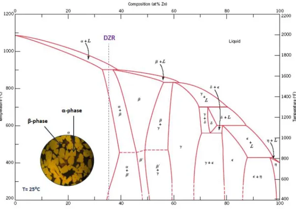
The phase diagram of the Cu-Zn system is presented in Fig. 2. Besides the zinc content, that can be up to 45% in weight, brass can have in its chemical composition, other minor alloying elements, not exceeding 5% in weight. Depending on the amount of Zn in the alloy, it is possible to distinguish two major types of brass alloys [2]: monophasic brass or alpha brass and biphasic brass (alpha + beta) or Duplex brass.
Fig. 2 – Phase diagram of Cu-Zn system. [2]
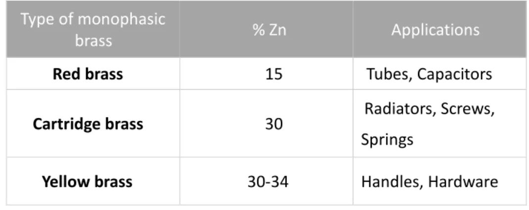
Monophasic brass
Monophasic brass, also called alpha brass, is characterized by presenting only the alpha phase in its composition. The zinc content of these brass alloys is lower than 35 wt.%. This phase is a zinc solid solution in copper with a face centered cubic (FCC) structure. These brass alloys are usually not thermally treated. Their ductility allows cold working, however, the higher the zinc content is, the less ductile the alloys and the cheaper they are. The alpha alloy has better corrosion resistance than the brasses with a higher zinc content.
Table I - Monophasic alloys.
Type of monophasic
brass % Zn Applications
Red brass 15 Tubes, Capacitors
Cartridge brass 30 Radiators, Screws,
Springs
Yellow brass 30-34 Handles, Hardware
Biphasic brass
These alloys contain normally a zinc content between 37% and 46% and present a microstructure characterized by two phases: an alpha phase and a beta phase. The percentage of these two phases depend on the zinc content of the brass. Higher percent of zinc corresponds to higher percent of beta phase, as can be seen in the phase diagram of Cu-Zn system (Fig. 2).
The beta phase is an intermetallic compound of copper and zinc with a temperature dependent solubility range, having a body centered cubic (BCC) crystalline structure. The presence of the beta phase in the alpha-beta brasses reduces cold ductility but greatly increases hot workability by extrusion or stamping and to die casting without hot cracking, even when lead is present. The alpha-beta alloys are also stronger and, since they contain a higher proportion of zinc, cheaper than the alpha brasses. They do however show higher susceptibility to dezincification corrosion and are therefore less suitable for service under conditions where this type of attack is likely to occur. Dezincification is a process which selectively removes zinc from an alloy, leaving behind a porous, copper-rich structure that has an inferior mechanical strength. This phenomenon can be caused by water containing sulfur, carbon dioxide, chlorine and oxygen. Stagnant or low velocity waters tend to promote dezincification as well.
Influence of additional elements on brass properties
Zinc is the most influential element that affects the properties of brass. As mentioned before, zinc determines the type of structure of the brass (monophasic or biphasic), defining two groups of brass alloys. The effects of other elements that may be present in the chemical composition of brasses are described below:
Aluminum – This element is added to the brass with the objective of protecting the brass alloys from oxidation during the melting and improve their fluidity, as well as reduce losses of zinc by evaporation. Aluminum enhances corrosion resistance to the brass due to the formation of a passive film on the brass surface. Mechanical resistance of the brass increases but ductility decreases.
Iron – Iron improves mechanical properties in general, particularly tensile strength and ductility. When other elements in the composition react with iron forming intermetallics, there is the disadvantage of creating hard spots in the brass surface, a defect that is undesirable in the polishing and machining operations. This reaction can occur with iron and silicon.
Lead – This element has a deep effect on the machinability of the brasses. High content of lead lowers the tensile strength, especially at high temperatures, that can create cracking. This means that the percentage of lead has to be carefully selected (and considering the brass applications) to ensure that the alloys can be machined, do not induce high temperature defects and is within the environmental and safety regulations of the countries of customers.
Tin – Tin is responsible for the improvement of corrosion resistance of the brasses, in particular, the dezincification resistance. However, high amounts of tin can cause cracking in the solidification of the piece.
Silicon – This element is a beta phase stabilizer of the brass alloy, making them harder and more mechanically resistant. It also improves the castability of these alloys. However, given silicon’s tendency to form hard spots with iron and manganese, its presence reduces the machinability and easiness of polishing of the brass. Maximum content of silicon in brass foundries is 0,05% in weight.
Arsenic – Arsenic is used in brass to avoid dezincification. Using very low contents (<0.2%) is just enough to improve the resistance to this phenomenon [3].
Boron – Boron is a grain refinement element. Grain refiners in casting alloys tend to reduce the amount of porosity located between large grains and decrease the size of the pores. This improves mechanical properties, especially fatigue strength [4]. Boron additions to the melt were in low quantities.
1.3. General description of the production process
Foundry
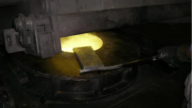
The foundry is the first process of production of the company. This particular process has as main goal the production of metal pieces of a Cu-Zn alloy. The production initiates at a central furnace for melting of the raw materials. These are loaded into the oven with the necessary quantities to produce the desired brass alloy (Fig. 3).
Fig. 3 - Central furnace in operation.
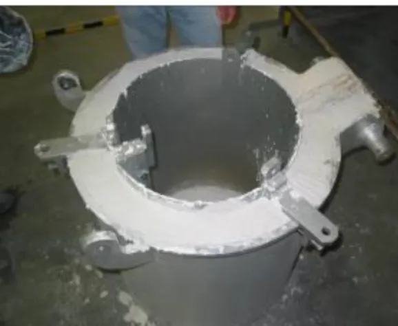
After this preparation, the molten brass is transported to the die casting stations in ladles (Fig. 4).
Fig. 4 - Distribution ladle for transportation and distribution of the liquid brass to the casting machines.
The casting stage is composed of six low pressure die casting stations and two gravity casting pieces of equipment. Each equipment requires one operator to control the casting process. The molten tank has a capacity of a little more than two tons of liquid metal.
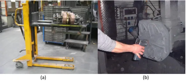
The dies are transported from the die storage to each casting machine when prepared (Fig. 5a). The liquid brass is then cast into metallic molds (made of a copper-beryllium alloy) by gravity or low pressure injection, acquiring the shape of the design of the mold. The die temperature measurements are done by an infrared thermometer (Fig. 5b). In this section, there is also the insertion of the sand cores. The cores are placed in predefined positions in the interior of the mold that permits to define the internal shape and cavities of the piece. The sand cores are produced by a hotbox process, where the sand mixed with a resin and hardener, acquires a determined shape and mechanical resistance after a thermal treatment when inside the metallic hotbox mold.
(a) (b)
Fig. 5 – a) Die transport to low pressure die casting machine; b) die temperature measurements by infrared thermometer.
After the solidification of the alloy, the next stage is the separation of the gating system from the brass product by sawing (Fig. 6). The few pieces with major visible defects are set aside from the accepted ones and are classified as waste. These pieces are then transported to the central melting furnace to once again be melted.
Machining
The machining department consists of the removal of excess material of the pieces and creation of details such as slots, threads, and holes. At the end of this section, a degreasing is done to the pieces, followed by an air leakage testing.
Surface finishing
Surface and shape finishing starts with a sequence of rough to fine sandpapers. Afterwards, polishing is done. These two steps are done manually or automatically, depending on the complexity of the piece and defects detected.
Galvanic coating
In the galvanic department coatings, the polished pieces are coated by electrodeposition of nickel and chromium (nickel electroplating or chrome plating, respectively). This process is done sequentially in tanks.
Assembly
The assembly is the last step of the production process. Here, the setting of all of the pieces to build a faucet takes place, to obtain the final product ready to be commercialized. This process is done in assembly lines where several tests are executed: visual control of the pieces, the actual assembly of the products and packaging. Following this, the packages are transported to the warehouse (for further transportation to the distribution centers).
1.4. Gravity casting in permanent metallic molds
In gravity casting, Grohe uses permanent metallic molds made of a copper and beryllium alloy. The liquid metal is cast by simply pouring the melt into the mold. This allows a repeated production of pieces with the same shape. To define the cavities of the metallic piece, removable cores are used. The cores can be either made out of metal, ceramic or sand. Given the abundancy and low cost of sand, Grohe fabricates sand cores for this purpose.
This type of casting is used for low volume productions, for pieces with a uniform wall thickness, with a limited amount of cutting operations and cores with simple shapes. This process can be used to produce complex pieces, but the quantity produced should compensate the cost of the molds. Foundry in metallic molds allows more uniform cast pieces with a better quality in surface finishing and better mechanical properties [5].
Weekly check-lists are done in Grohe to identify and ensure quality of the molds. If a mold presents surface wear, due to mass production, they are sent to the Tooling section to be corrected.
During the casting sequence, the molds are coated with a film of graphite by spraying. The importance of graphite is the demolding of the brass components, to decrease production times and increase quality. Graphite is also used in the cooling tanks, whose function is to lower the temperature of the molds (from 105±10°C to 50°C at the outer surface).
Quality control in casting involves measuring the temperature of the molds by infra-red thermometry and by daily measurements of the graphite concentration in the tanks.
1.5. Low pressure casting
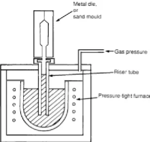
Low pressure die casting, is a process in which an iron (or ceramic) riser tube is connected to a copper-beryllium die above and extends into a furnace of molten metal below. The furnace is then pressurized to fill the die by forcing fluid up through the sprue (Fig. 7). Once the casting has solidified the air pressure is reduced allowing the rest of the metal still in liquid form in the tube to recede back into the furnace. Low pressure die casting is used for high production rates, for better surface quality, and when high temperature heat treatment is needed to improve strength.
It should be taken into consideration that the tubes may crack over time, reducing their longevity and shortening the replacement schedule. The formation of these fracture defects allows slag and/or air to be in contact with the liquid brass, possibly forming slag inclusions into the casting.
Fig. 7 - Riser tube placed in low pressure die casting schematic.
1.6. Lead present in drinking water
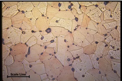
As referred above, lead is frequently added to copper alloys to increase their machinability. The role of lead in copper alloys is to act as a lubricant, therefore reducing tool wear. The pure copper solidifies first, leaving the lead to solidify last as almost pure lead globules at the grain boundaries. The size and concentration of lead particles depends upon the concentration of lead in the alloy. The microstructure of the as cast copper lead alloys consists of pure alpha copper dendrites, with lead globules between the grain boundaries (Fig. 8).The higher the lead content of the alloy the more lead globules are present in the structure.
Fig. 8 - Microstructure of Cu alloy. Nominal composition: 60-63% Cu, 33-37% Zn, 2.5-3.7% Pb (Scale line length 25µm). [6]
Brass alloys have always been important materials for piping, fittings, faucets and other plumbing components. Brass companies manufacturing these alloys and components for plumbing have been at the leading edge of developing lead-free and low lead alloys thereby ensuring that consumers have products that are safe, durable and reliable.
There are possible elements that can substitute lead for its machinability. The term machinability refers to the ease with which a metal can be cut permitting the removal of the material with a satisfactory finish at low cost. Materials with good machinability require little power to cut, can be cut quickly, easily obtain a good finish, and do not wear the tooling much. The factors that typically improve a material's performance often degrade its machinability. Therefore, to manufacture components economically, engineers are challenged to find ways to improve machinability without harming performance.
Machinability can be difficult to predict because machining has so many variables. Two sets of factors are the condition of work materials and the physical properties of work materials. The condition of the work material includes eight factors: microstructure, grain size, heat treatment, chemical composition, fabrication, hardness, yield strength, and tensile strength. Physical properties are those of the individual material groups, such as the modulus of elasticity, thermal conductivity, thermal
expansion, and work hardening. Other important factors are operating conditions, cutting tool material and geometry, and the machining process parameters.
In order to reduce or eliminate lead completely of the brass alloys, there are considered elements of substitution. Bismuth has a similar to lead but it is a considerably more expensive addition, as well as selenium that was tested before in Grohe with unsatisfactory results.
Lead may be present in tap water as a result of household plumbing systems in which the pipes, solder or fittings contain lead. The lead can be leached from the materials and result in high lead concentrations in drinking water. The amount of lead dissolved from the plumbing system depends on several factors, including the presence of dissolved oxygen, chloride, pH, temperature, standing time of the water and acidic water being the most plumbosolvent (the ability of water to dissolve lead). Although lead can be leached from lead piping indefinitely, it appears that the leaching of lead from soldered joints and brass taps decreases with time. Soldered connections in recently built homes fitted with copper piping can release enough lead (210-390 µg/l) to cause intoxication in children [7].
In 1988, it was estimated that a lead level of 5 µg/l was exceeded in 1.1% of public water distribution systems in the United States of America [7]. A more recent view of lead levels in drinking water in the USA was found at 2.8 µg/l. The median level of lead present in water samples collected in five Canadian cities was 2.0 µg/l. Another recent study in Ontario, Canada, found that the average concentration of lead in water consumed over one week period was in the range of 1.1-30.7 µg/l, with a median level of 4.8 µg/l [7]. It is registered that lead concentrations in 40% of water samples in Glasgow, Scotland, exceeded 100 µg/l, due to plumbosolvency of the water [7]. If a concentration of 5 µg/l in drinking water is assumed, the total intake of lead from this source can be calculated to range 3.8 µg/day for an infant to 10 µg/day for an adult.
According to United States Environmental Protection Agency (EPA) regulations, the maximum contaminant level of lead in drinking water is 15 µg/l, expecting no risk to health. This level allows a margin of safety for public health goals. If level exceeds this value, actions are required intended to reduce the level of lead. Actions may include investigation, recommendation of treatment, installation of treatment, checking of source water, removal of lead containing plumbing, and public education. Since most of
the lead found in drinking water leaches from the customer's pipes, fittings, and solder rather than from the source water, special sampling is necessary for research and development.
Chapter 2. Characterization of Grohe low lead brass
alloys
2.1. Types of alloys
Grohe Portugal produces three different low lead brass alloys, varying in the amount of zinc and lead. Their composition is given in Table II.
Table II - Chemical composition of the three alloys. Elements
Alloys % Cu % Zn % Pb % Al % Fe ppm B elements % Other
Grohe 0 Light 57-63 37-39 0.2-0.8 0.2-1.2 ≤0.5 1.7 ≤0.9
Grohe 0 63-65 34-35 ≤0.2 0.3-0.8 ≤0.5 1.7 ≤0.9
DZR 61-63 35-36 1.4-1.6 0.4-0.8 ≤0.5 1.7 ≤0.9
2.2. Microstructural characterization
Metallographic preparation
Many important macroscopic properties of metallic materials are highly dependent of the microstructure. Critical mechanical properties, like tensile strength or elongation, as well as other thermal or electrical properties, are directly related to the microstructure. The understanding of the relationship between the microstructure and macroscopic properties plays a key role in the development and manufacture of materials and is the main mark of metallography.
Metallography is the study of the microstructure of all types of metallic alloys. This material characterization technique involves the preparation of specimens for microscopic examination and the study of microstructure in relation to the mechanical properties of a particular material. It can be more precisely defined as the scientific observation in determining the chemical and atomic structure and spatial distribution of
the constituents, inclusions or phases in metallic alloys. These same principles can be applied to the characterization of any material.
This material characterization (microstructure analysis) can contribute to quality control in the industry, making it integral to its system and industry growth. The analysis can potentially verify information such as if the heat treatment or cooling of the material provided the desired hardness or the desired grain size, if formation of precipitates occurs and what size, if formation of defects occurs in the final product, determining product reliability or why the material failed, among other information that depend on the microstructure by using optical microscopy.
The steps for specimen preparation include cutting, grinding and polishing of the alloy. Small portions of liquid brass at temperature of 1050°C, were poured from the central furnace of the foundry, in a cup (for solidification) as specimens for further microstructure analysis. The specimens were air cooled to room temperature and cut to approximately 1 cm x 1 cm in dimensions, using a saw. The surface was ground and for optimal polishing the specimens were further processed at DEMaC using grinding paper GRIT600/P1200 and polishing cloths with diamond paste of 6, 3 and 1 μm.
The chemical attack was performed by using a solution containing the chemicals presented in Table III with their respective quantity.
Table III - Constituents of chemical attack.
Chemical compound Formula Physical state Quantity
Iron trichloride FeCl3 solid 3.5 g
Hydrochloric acid HCl liquid 21 cm3
Ethanol C2H6O liquid 75 cm3
The immersion time of the specimens in the solution was 30 seconds. Residues of the solution in the samples were removed by rinsing with water and again with alcohol. Samples were dried until no moisture was observed on the surface.
Phases and morphology
Optical micrographs of the brass microstructures were taken using the optical microscope Leica Model EZ4HD and the Infinity Capture software by Lumenera Corporation. Fig. 9 to Fig. 11 correspond to the three Grohe alloys.
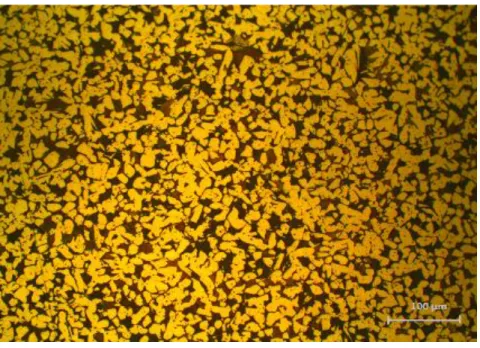
Fig. 9 - Microstructure of Grohe 0 Light brass.
Fig. 11 - Microstructure of DZR brass.
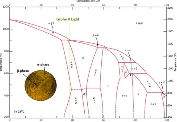
Taking the copper-zinc phase diagram [2], the different morphology of the grains can be attributed to the alloy composition, microstructural evolution during cooling and amount of grain refining elements. At room temperature, the three alloys are identified in the α + β area of the Cu-Zn phase diagram (Fig. 12 - Fig. 14).
The Grohe 0 Light has an average composition with a typical Zn content of 38%, when considering only the Cu and Zn elements, Fig. 12. This corresponds to a hyperperitectic alloy with the following microstructural evolution when cooling from the liquid phase: firstly, the liquid crystallizes as β phase almost immediately due to the very narrow solidification temperature range; then below approximately 900°C the α phase precipitates. The α phase appears as needles inside the β mother grains and on their grain boundaries as illustrated by the micrograph in Fig. 9.
In the Grohe 0 brass the Zn content is much lower, with average values around 34 wt%, placing this alloy at the left side of the peritectic composition, Fig. 13. Moreover, this is the composition with the smallest amount of grain refining elements. Accordingly, the α phase precipitates out first from the liquid phase and form a Widmanstatten structure solidifying in plates along preferred growth directions [8]. Then, at the peritectic temperature, the remaining liquid phase reacts with the
periphery of the α grains, forming the β phase, of darker contrast in the micrograph of Fig. 10.
Fig. 12 - Phase Diagram of Copper-Zinc and composition of Grohe 0 Light brass.
The DZR composition has a slightly richer zinc concentration (Fig. 14), thus with a larger amount of β phase but with a smaller grain size due to the larger amounts of grain refining elements (Table II). The resulting microstructure consists of an equiaxed morphology of α grains in a β matrix as shown in Fig. 11.
Fig. 14 - Phase Diagram of Copper-Zinc and composition of DZR alloy.
Grain size
Analyzing grains in metallic alloy samples can be potentially important for quality control. When a metallic alloy is processed, the atoms within each growing grain are lined up in a specific pattern, depending on the crystal structure of sample. With growth, each grain will impact others and form an interface where the atomic orientations differ. It has been established that the mechanical properties of the sample improve as the grain size decreases [9]. Therefore, alloy composition and processing must be carefully controlled to obtain the desired grain size.
The grain size, shape and distribution were analyzed via optical microscopy, to assess the quality of the samples. The size of the brass grains and distribution in the alloys help determine how a slight change in the alloy(s) composition will perform in new conditions. A rigorous internal quality control procedure may require that these types of analysis and results be documented and archived for future references and comparisons.
Grain size measurements were determined of the three specimens by using ImageJ Software (Table IV).
Table IV - Measurements of α grain sizes on the three brass samples.
Alloy Grohe 0 Light Grohe 0 DZR
Type of grain Elongated Elongated Equiaxial
Average dimension (µm)
24.0 (in length) 3.2 (in width)
96.5 (in length)
16.8 (in width) 15.7 (in diameter)
2.3. Hardness
Hardness testing is typically undertaken to measure resistance to plastic deformation, a value of importance to the determination of casting quality in a range of industries and applications. Exposure to pressures and high temperatures in manufacturing has the potential to affect the performance of metal alloys castings. Due to complex product geometries and the correlation between hardness and tensile strength in metal alloys, hardness testing can indicate and establish if the castings will perform in their intended application, making this analysis a quality control process in industries. Accurately determining the hardness of a material for any given application involves several factors including the type of material, specimen geometry, surface conditions, exposure to heat treatment processes, and production requirements.
A range of different hardness tests may be applied to determine different hardness values for the same test specimen. Among the most common tests used to determine material hardness are the Rockwell hardness test, the Brinell hardness test
and the Vickers hardness test. These three tests measure hardness by determining resistance to the penetration of a non-deformable cone, ball or pyramid indenter.
In the Rockwell method of hardness testing, the depth of penetration of an indenter following application of a minor load and a major load is measured. The type of indenter and the test load determine the hardness scale which is expressed in letters such as A, B, C. Rockwell hardness test typically uses three different types of indenter: diamond cones, steel and cemented carbide spheres. By using different indenters with different loads, the different Rockwell standard tests are available.
The Rockwell hardness test uses an indenter with a determined load to cause an indentation on the surface and directly measures the indentation depth as a representation of the material’s hardness. The deeper the indentation is, the lower the hardness value becomes. To guarantee good contact between the indenter and the sample surface, a Rockwell hardness test preloads the indenter with 10 kgf (98 N) before applying the actual load. The load that is applied depends on the material hardness. The Rockwell hardness formula is defined as:
HR= K –h1−h2S
Eq. 1
HR is the unit for Rockwell hardness and K is a constant describing the indenter tip. A steel indenter (used for the experiment) has a K value of 130; and h2 is the indentation depth in mm resulting from the preload of 10kgf; h1 is the indentation depth after the main load has been removed; and S is another constant with the value of 0,002 mm, which defines a unit depth for indentation [11].
The brass hardness is an important characteristic as an indication of its performance during casting. If the alloy is ductile (HRB under 45), it will present a poor filling of the mold. On the other hand, a hard alloy (HRB above 60) has a tendency to crack during cooling [3]. This way, the control of the brass hardness is a prompt method to verify the quality and performance of the alloy in foundries.
The procedure was done using Rockwell hardness B (applied for copper alloys) standard using an Affri System Brevetti Hardness Tester using a 1/16” inch (1.588 mm) diameter steel sphere indenter and a load of 100kgf.
Fig. 15 - Rockwell B hardness of the three Cu-Zn alloys.
The results in Fig. 15 show that Grohe 0 alloy has a lower hardness comparatively to Grohe 0 Light and DZR brasses. This result can be correlated with the grain size of Grohe 0 resulting in the highest value of the three specimens (Table IV). Grohe 0 Light and DZR alloys resulted in an identical hardness. This may be explained by similar grain sizes, despite the different morphology between Grohe 0 Light and DZR.
0 10 20 30 40 50 60 70
Rockwell B Hardness
Grohe 0 Light DZR Grohe 0HRB
Chapter 3. Defects in low pressure casting
3.1. Common defects in brass alloy castings
The brass alloys may present a wide variety of defects. Defects in foundry can be classified in the following categories: cavities, surface defects, incomplete shapes and inclusions. Imperfections on the brass alloy may result by a variety of circumstances and not just a single cause. This explains the wide variety of types of defects found in foundries.
The following Table V presents a broad classification of defects in a foundry [3].
Table V - General classification of defects in foundries.
Type of defect Examples
Cavities Pores Shrinkage
Surface defects High roughness
Incomplete shapes Incomplete casting Interrupted casting Inclusions Metallic inclusions
Non-metallic inclusions
In the Grohe process, different defects can occur and are detected later on. These defects are presented in detail in Table VI below [3].
Table VI - Foundry defects.
Defect Cause Correction
Sand core: broken or displaced
Wrong placement of the sand core; Incorrect sand core design; Sand core
movement after closing die; Poor preparation of sand
Place sand core correctly; Correct sand core design; Check sand core and cavity dimensions; Verify sand
composition Cold shut Casting interrupted; Low casting
temperature; Low die temperature; Insufficient risers
Secure a continuous casting of the brass to the die; Increasing casting temperature; Reducing die cooling
time in bath tanks; Check riser dimensions
Misrun (an incomplete
casting)
Low casting temperature; Insufficient risers; Low die temperature; Thin die coating; Deviation from alloy chemical composition; Slow casting;
Increase casting temperature; Increase number of risers; Reducing
die cooling time in bath tanks; Increase die coating thickness; Chemical composition corrections;
Increase casting speed Shrinkage Incorrect casting design, not allowing
directional solidification; Brass contraction during solidification not
compensated by sprue dimension; High brass temperature; High gas
pressure
Promote directional solidification; Modify gating system; Decrease casting temperature, limiting brass contraction in liquid state; Decrease
casting temperature and increase number of risers in the die Pores Air drag during casting, by turbulence;
Insufficient risers in the die; Low sand core permeability; Liquid brass containing high quantity of dissolved
gases
Modify gating system in order to reduce turbulence; Increase dimension and number of risers; Sand core quality control; Humidity
control on the die, sand cores and ladles
Cracks Thermal shock; High casting temperature; Coarse microstructural
grains; Uneven die temperature;
Increase die coating thickness; Decrease casting temperature; Addition of grain refiners; Check die
temperatures Hard spots Presence of oxidized iron, even in small
proportions; Presence of hard spots during polishing process; Inadequate
alloy chemical composition
Low iron and silicon content ingots; Improve brass deoxidization, by
aluminum addition Sand
inclusions
Sand detachment from cores due to deficient curing; Poorly cured sand
cores; Turbulent brass flow; Insufficient risers in sand core box
Improve sand core curing conditions, mainly by additive contents and temperature control; Modify gating system, avoiding narrow curves, abrupt brass projections against sand core walls; Riser addition for sand core boxes (for excess gas release)
Quality castings are an essential requisite for produced brass pieces. The production of castings requires that defects such as inclusions and porosity (considered gas inclusions) are minimized, even eliminated, to reduce the harmful effects on the mechanical properties
The presence of hard non-metallic inclusions in brass alloys can not only degrade the mechanical properties of the final product but also create a number of other processing-related problems. These issues include surface defects and influence on the machining of the castings. In molten copper alloys, they can cause increased gas porosity, decrease in fluidity and overall higher processing costs.
Gas porosity consists on the entrapment of gas in a solid metallic body, after cooling the casting. This defect occurs because the solubility of gas in liquid metal is significantly greater than that in solid metal. As the brass is in liquid form, it readily absorbs surrounding gases, most notably oxygen, nitrogen and hydrogen [11]. Gas porosity may be present on the surface of the casting or may be trapped inside the metal, which reduces strength in its proximity.
Gases absorbed during casting or solidification can come from two primary sources. They may be initially present in the sand (from the sand cores) or die surface. Secondly, they may be formed as a result a chemical reaction of materials within the die, including the water from the cooling tanks (after the dipping of the die) or ceramic coating moisture. Turbulence from pouring the liquid brass into the die can also introduce gases, so the designs of the dies should account for ways to minimize such turbulence. Precipitation is a technique involving the reaction of the gas with another element to form a compound that will form a dross that floats to the top.
Other sources include the reactions of the molten brass with grease or other residues on the die surface such as, water particles from the bath immersion or from the ceramic coating in slurry form. Hydrogen can be produced by the reaction of the brass with humidity or residual moisture in the die. Drying the die more efficiently can eliminate this source of hydrogen formation [12].
Gas bubbles in smaller dimensions are designated as porosities, while larger gas bubbles are designated as blowholes (or blisters) in the foundry industry [13]. Such defects can be caused by air entrained in the melt, steam or smoke from the casting
sand, or other gases from the melt or die. Proper foundry practices, including melt preparation and die design, can reduce the occurrence of these defects.
Although a substantial number of methods are used to remove the inclusions either prior to or during casting, such as cleaning all furnaces, the main melting furnace or the low-pressure furnaces and using disposable ceramic filters, the problem of measuring metal cleanliness through a sensitive, quantitative method is still a difficult task. The difficulty is further compounded by the fact that the inclusions to be measured are usually very small in dimensions.
3.2. Characterization of potential defect sources
After the microstructural and mechanical characterization of the Grohe low lead alloys, another topic industrially relevant that was addressed during this internship was the full characterization of casting process consumables and aids and other sources of potential defects in the final product.
Ceramic Coatings
A gravity or low pressure die casting must have good surface finish and be easily and rapidly produced. To achieve this, the die must be coated with anti-adherent materials with multi-functional results. The die coating serves several functions listed on Table VII.
Table VII - Functions of a Die Coating. Die coating functions
Protect the accurately machined die face Ease the release of the casting from the die Control heat flow from the metal to the die Provide good surface finish to the casting
The coating should also prevent build-up of residues on die surfaces and be free from excessive fumes. The control of heat flow from the brass to the die is the most important property of the coating, allowing control over filling the thin sections and the solidification of the casting. The thermal insulation properties of the applied coating layer are determined by three key factors, namely the coating composition, the layer thickness and coating layer porosity.
The die coatings used in Grohe are formulated using water as carrier and a refractory filler or blend of fillers. There are two characteristics required in coatings:
1. Insulating: Contain blends of insulating minerals such as talc, mica, titanium dioxide, and alumina;
2 Lubricating: Based on colloidal graphite or boron nitride to aid release of the casting [9].
Thermal conductivity and particle size distribution are key properties to characterize the coating material. The die caster needs to consider the most important aspect of the particular casting to be produced when selecting the die coating or coating combination, such as high insulation to avoid misruns, lubrication and smooth surface finish. It is generally accepted that a rough coating surface provides maximum insulation through the formation of an air gap at the brass/coating interface during casting. The air gap arises from the high surface tension of the brass alloy. The low brass/refractory contact area of a rough coating surface significantly reduces heat transfer and consequently favors metal flow. In addition, coarseness and angularity of the refractory particles enhances metal flow by continuously rupturing the oxide skin on the molten brass surface as it flows over the die. Conversely, a smooth coating based on fine fillers provides a larger contact surface area and higher heat transfer rate. This higher heat transfer can lead to crack and shrinkage formation due to uneven brass cooling [13].
When the liquid brass is cast against the sand core, there may be a physical effect and a chemical reaction at the sand/brass interface. Either may result in surface defects on the finished casting. For many years, foundries made their own coatings, usually based on graphite [14]. The technology of coatings has become highly developed, and most foundries now purchase coatings from specialist suppliers. It is
important to recognize the potential savings in die shot-blasting and cleaning costs that can be made by using a good quality and well applied coating.
Grohe utilizes two separate ready-to-use die ceramic coatings, already prepared for a fast application (Table VIII). These so-called ready-to-use coatings are supplied from CeraNovis GmbH (Germany) as slurries but may require a small water addition to allow the user to control the final viscosity of the suspension to suit the specific application. During transport and storage of these suspensions for coatings, there is always some sedimentation of the refractory filler, often a high-density material, but such segregates are can be reincorporated by a stirring action.
Table VIII - Ceramic Coatings descriptions.
Ceramic Coating Description
BC15 Green-brown slurry
BC11 White slurry
The application methods for coatings are dipping, brushing, swabbing, spraying and overpouring/flow-coating [12]. The method in the Foundry section of Grohe for coating application is by spraying. This is a faster technique than brushing but penetration and coverage of the sand is not as good as with brushing. Skill is required to ensure that deep pockets and re-entrant angles are fully coated. It is best used on dies having rather simple shapes. Generally, sprayed coatings are of much lower viscosity than brushing or dipping varieties [9]. They are applied under pressure from a spray gun delivering a spray of finely divided droplets on to the surface to be coated. A degree of thixotropy is desirable to prevent the coating from suffering particle agglomeration [12].
Insulation by a coating layer is dependent not only on thickness but also on porosity. This property in turn is influenced by application method and conditions. The degree of pore formation can be essentially determined by the rate of evaporation of the water carrier on contact with the die. The temperatures of the dies are in a range of 90°C to 130°C when coatings are applied. The material’s consistency and spray equipment also influence the quality of the deposited coating layer.
The ceramic coatings used as die coatings at Grohe were characterized with respect to particle size distribution using a Coulter LS Particle Analyzer; specific surface area by BET technique (Gemini V2.00) and phase composition by X-ray diffraction (XRD Rigaku Geigerflex).
XRD diffractograms of the dried coating suspensions BC15 and BC11 are presented in Fig. 16 and Fig. 17.
Fig. 16 - XRD of BC15 dried suspension.
As observed in the XRD analysis of Fig. 16, the ceramic slurry of BC15 is based on silicon carbide with a moissanite crystalline structure. SiC is useful for industrial applications due to its hardness and combination of thermal conductivity/lubricity, properties required in Grohe or any industry for coating application.
Fig. 17 - XRD of BC11 dried suspension.
The XRD of BC11 (Fig. 17) showed a complex mixture of compounds of silicon carbide, alumina and boron nitride. Each compound present has its own role: SiC for increased mechanical stability; Al2O3 for thermal insulating purposes and BN for high
temperature lubrication.
From Fig. 18 and Fig. 19, it is shown a significant difference in the particle size distribution of both ceramic suspensions. Average particle size of BC15 is 192 µm composed by a bimodal distribution centered at about 40µm and 600µm, while BC11 has an average of 3.8 µm, Table IX. A decrease in particle size is noted by a factor of 50 between BC15 and BC11. The difference in particle size distribution can also be clearly seen on the data of Table X. Also, the BC11 suspension reaches up to 15 times higher specific surface area (Table XI) than BC15.
Fig. 18 - Particle Size Distribution of BC15 suspension.
Fig. 19 - Particle Size Distribution of BC11 suspension.
Table IX - Average and median grain size of BC15 and BC11.
Ceramic BC15 BC11
Mean (µm) 192.0 3.8
Table X – Cumulative particle size distribution of BC15 and BC11.
<10% <25% <50% <75% <90%
Size (µm)
BC15 8.5 21.6 53.2 148.7 700.3
BC11 0.36 0.79 2.43 5.83 9.99
Table XI - Specific Surface Area.
Ceramic slurry BET Specific Surface Area (m²/g)
BC15 0.53
BC11 7.74
Ceramic Filters
Any copper alloy melt can contain many non-metallic particles, films, or clusters in a wide range of sizes, from a few microns to several millimeters. Whatever the size and chemical composition of these inclusions, they are detrimental to the finished casting. The removal of such non-metallic inclusions may be accomplished by filtration. Another issue is the turbulence of the brass melt which should be avoided, to refrain copper oxidization. Turbulence may lead to a higher formation of oxides from exposure of clean brass to the atmosphere.
The introduction of ceramic foam filters to the brass industry allowed to trap inclusions through the filter body, with the objective of resulting in impurity-free, smooth flowing brass entering the die cavity.
The filter material provided by LANIK is characterized by its geometrical dimensions, the size of the structural cells, their distribution and arrangement in the filter, and by their porosity (Fig. 20). These ceramic filters are made in various grades of open porosity, usually with 10, 20 and 30 ppi (pores per linear inch) as used by Grohe, existing also finer pores (50, 60 ppi) in the market.
Fig. 20 - Ceramic Foam Filter used in Grohe (10 ppi). Arrows point to thin filaments across the large pores.
The ceramic foam filter consists structurally of a block of open pore ceramic foam of varying thickness and cross-sectional area. Any solids present in the molten brass may deposit onto the cell walls, becoming trapped within the voids of the filter medium. Also, they may become dispersed through a part or all of the filter volume. The filter thus has the advantage of having a large surface area for capturing and can trapping particles much smaller in size than the pores of the filter.
Surface forces may be responsible for the retention of solids. Therefore, the filtration process in this case, is not only one of physical separation as in screening and separation, but rather melt filtration is a two-step serial transport process. First, as a result of bulk brass fluid flow, the particles are transported to the filter surface. In the second step, capture of solids occurs due to interfacial or surface forces. A physical separation is not the only mode of capture. Particle attachment can be a result of forces developed through pressure, chemical, or Van der Waal effects [16].
The particles removal efficiency can be improved by either increasing filter width or by decreasing melt velocity. However, this last action would interfere with the machine’s pre-determined casting curve and may form misruns or incomplete castings. If flow resistance increases, as a result, drag forces exerted on either contacting
particles or particles already captured will increase. This can lead to lower adhesion efficiencies since particles may not be able to adhere to the filter surface due to increased drag force, even if they are able to make a contact with them. Similarly, increased drag forces may dislodge previously captured particles if the forces of adhesion are overcome. This would mean that the particles would be released into already filtered liquid brass. The inclusions released may as well originate from the filter, any furnace cleaning equipment or even originate in the actual furnace. A resistance flow due to the presence of the filters may lead to a slow production considerably due to the large flow resistance experienced by the brass and the subsequent necessity of filter change.
Filtration with ceramic foam is a process that is complementary to existing metal treatment practices and is extensively used both in ingot making as well as for shaped castings, such as those produced at Grohe. For the latter, the ceramic filters placed in the gating system do not only retain particles but also promote smooth, non-turbulent die filling, so that oxidation and dross formation are minimized [17].
A ceramic foam filter can be installed prior to the casting with insignificant cost. However, it only has a limited life because they are disposable, utilizing them one per casting. The first and main macroscopic observation of the ceramic filters was of their characteristic brittleness. Due to the brittleness of the ceramic filters, there is a risk of fine particles entering the die to form inclusions in the castings. The brittle filters continuously failed at capturing particles in some castings. A reason for particle release can be by a slight change in flow velocity or vibrations. Furthermore, the formation of fine particles would occur frequently due to breakage or chipping whether stored in its original box, or prepared at the die casting machine.
Phase composition of a ceramic filter used by Grohe was determined by XRD analysis (Fig. 21). The major phases present are silicon carbide and silica that in the form of low cristobalite (orthorhombic) [18].
Fig. 21 - XRD analysis of a ground ceramic filter.
A compression test was performed on the ceramic filters to quantify their compressive strength. The samples were cylindrical with dimensions of 4 cm of diameter and 1 cm of height. The load application rate was 1 mm/min on a Shimadzu AG-X/R Autograph tensile testing machine. As the results in Table XIII show, the average of deformation the ceramic filters are subjected to is approximately 10% with an average of maximum stress of 1.34 MPa.
Fig. 22 - Compression testing on ceramic filters
Table XII - Compression on ceramic filters.
The average maximum stress of the ceramic filters determined was superior to the maximum pressure the brass is injected: 1.34 MPa > 0.03 MPa. Therefore, the possibility of the ceramic filters fracturing (as a whole) due to the brass pressure during the casting is very low. However, the hypothesis of fine filter particles being previously separated from the material and contaminate the casting, is not excluded. In addition,
Sample # (10ppi) Max. Force (N) Max. Stress (MPa) Deformation (%)
1 1739 1.38 9.08 2 2040 1.62 13.27 3 1967 1.57 13.10 4 1329 1.06 6.92 5 1336 1.06 7.55 Average 1682 1.34 9.98 Standard Deviation 338 0.27 3.03
indicated in Fig. 20). These fine filaments might break under the flow of the molten brass.
It may be necessary to cut out the portion of the runner containing the filter to be recycled separately from the bulk of the scrap. Filters made of silicon carbide, such as the ones used in Grohe, are subjected to some limitations in their re-melt capability [12].
Slag and iron raw material
During the brass casting operation, slag is generated as a waste product and it can be a source of inclusions in the final components. This material is collected from every furnace in the foundry and processed by an external service provider, for recycling of all wastes containing brass from the production process.
Another possible source of defects can be the raw material of the alloying element iron, present in all three alloys. Iron is an integral part of the alloys for mechanical properties improvement in general, particularly tensile strength and ductility. The iron raw material used for melting is in chip form.
A slag sample from one of the deposits in the Foundry and an iron chip were analyzed by SEM/EDS and X-ray diffraction.
The XRD analysis in Fig. 23 presents the phase composition of brass slag originated from the casting process. The peaks on the X-ray diffractogram correspond to compounds formed, zinc oxide and silicon oxide.
Fig. 23 - XRD diffractogram of brass slag.
The generation of zinc oxide occurs due to high temperature dezincification from the liquid. Zinc is a highly reactive metal, as seen in its galvanic series ranking. This reactivity stems from the fact that zinc has a very weak atomic bond relative to other metals. Studies have shown leaching and recovery processes for zinc and copper from brass slag by sulfuric acid [19]. This technique allows material recycling from waste. The results obtained revealed that zinc and copper are successfully recovered from these secondary resources, where the percent recovery amounts to 95% and 99% for zinc and copper, respectively [19].
The result of the SEM-EDS analysis of the iron raw material chip can be observed on Fig. 24. The SEM image (Fig. 24) shows the machined surface of the material where only peaks of iron are detected in the EDS spectrum.
![Fig. 2 – Phase diagram of Cu-Zn system. [2]](https://thumb-eu.123doks.com/thumbv2/123dok_br/16059053.1105876/20.892.157.738.109.540/fig-phase-diagram-cu-zn.webp)