! "
# " $
% & '
& ( !
% ' ) * ) " +
% + , - .
!
# " /
' 0 %
% - 0 %
- +
!
% ' ) * ) " +
% + , - .
%% "
# " $
& 1 & "
-! "
#$ % #
&
TiN/TiAlN multilayers were deposited by radio frequency, r.f., reactive magnetron sputtering by using titanium and aluminum targets with 10 cm diameter and 99.99% purity in an argon/nitrogen atmosphere, applying a substrate temperature of 300 °C. WC inserts were used as substrates to improve the mechanical and tribological properties of TiN/TiAlN multilayered coatings compared to other types of coatings like TiAlN monolayers and to manage greater efficiency of these coatings in different industrial applications, such as machining, and extrusion. Their physical, mechanical, and tribological characteristics were investigated, including cutting tests with AISI 4340 hardened steel (50 HRC) to assess wear as a function of the period and number of bilayers. A comparison of the properties of TiCN-Al2O3-TiN monolayers coatings and the [TiN/TiAlN]300 multilayers with individual layer thicknesses of 10 nm revealed a decrease of flank wear (around 33%) for [TiN/TiAlN]300 multilayers and a reduction of flank wear (around 13%) for coatings with 300 layers when is compared with [TiN/TiAlN]200 coatings. They also showed better machining properties onto hardened AISI 4340 steel pieces, when compared to uncoated WC inserts. These results open the possibility of using [TiN/TiAlN] multilayers as new coatings for tool machining with excellent industrial performance.
Keywords: hard coatings, multinanolayers, tool wear, cutting tools
Introduction
1
Multilayered structures have been studied extensively and used for many years in coating technology to improve performance in industrial use. Among these multilayered structures, there are anti-wear coatings for applications in machining processes (Braic et al., 2003) (Musil, 2000). High hardness, good adhesion to the substrate, high chemical stability, and low-friction coefficient make these multilayered structures (Holleck, 1986) good options to diminish wear. In recent work, the high hardness and toughness of the nanometric layers in multilayered coatings have shown additional advantages as protective coatings against corrosion and wear of tools and machined parts. Some of these multilayered systems are denominated superlattices, e.g., Zr/ZrN, ZrN/TiN, and TiN/TiAlN, which evidence hardness above 30 GPa and greater efficiency in high-speed machining (Holleck, 1986).
TiN and TiAlN films are known for their important physical characteristics which depend mainly on deposition parameters like:
Paper accepted August, 2009. Technical Editor: Anselmo Eduardo Diniz
heat is distributed onto the tool, the piece, the chips, and a small portion onto the environment. The heat on the chips and on the piece may facilitate the cutting process, but heat on the tool will produce a decrease in its useful life; thereby, affecting the cutting process (Shaw, 1984) (Komanduri et al., 2001). In this work, titanium nitride (TiN) and titanium aluminum nitride (TiAlN) multilayered films were deposited and characterized via reactive r.f. magnetron sputtering, and the process parameters were optimized to prepare TiN/TiAlN multilayers to study the effect on physical properties like high hardness, high wear resistance, and good adhesion to the substrate. The main purpose of this work is the evaluation of the influence on the mechanical properties of the number of [TiN/TiAlN]200 and [TiN/TiAlN]300 heterostructures as compared to
properties of a TiCN-Al2O3-TiN nano-structured monolayer and
inserts with polycrystalline cubic boron nitride (PCBN) substrates and different types of coatings that yielded good durability performance.
Nomenclature
PCBN = Polycrystalline cubic boron nitride Sccm = Standard cubic centimeter per minute r.f. = Radio frequency
HRC = Hardness Rockwell C HSC = High-speed cutting % = Percentage W = Power (watts)
doc = depth of cut (mm)
X = Amplifications in optical microscopy
d = Feed rate (mm/rev)
Greek Symbols
vc = Cutting speed (m/min) Subscripts
[]n numbers of layers
Experimental Details
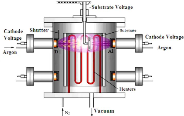
TiN/TiAlN heterostructures were grown by using the r.f. magnetron sputtering (13.56 MHz) technique at the Center for Technological Development, CDT-ASTIN, SENA Regional Valle, which is part of the Center of Excellence for Novel Materials – CENM in Colombia (www.cenm.org) (see Fig. 1). TiN/TiAlN films were also deposited onto WC insert substrates. The sputter target was pure titanium (99.99%) and aluminum (99.95%). The sputtering gas used was high-purity argon (99.999%). The base pressure was under 6 x 10⁻⁵ mbar. The composition of the gas mixture was controlled by flow meters and the argon flux (50 sccm) was fixed and corresponds to 93% of the total argon gas. The N2 (99.99%
purity) flux ranged from 7% of the total flux used as gas, corresponding to (3.7 sccm). The deposition chamber pressure during film deposition was 6 x 10⁻³ mbar. The r.f. power was always
300 W for Al and 400 W for Ti. The substrate holder was kept at 300 °C and a negative r.f. bias was applied to the substrate around -100 V. The deposition parameters used are shown in Table 1. Prior to TiN/TiAlN deposition, the targets were cleaned by argon glow discharge and then a pure thin Ti layer, with thickness of 5 nm, was first deposited to improve TiN adhesion to the substrate. Special care was taken to generate the multinanolayer effect of positioning the Al target discharge. During deposition in N2 atmosphere, the
fluxes of the reactive gases were fixed. These discharges were periodically interrupted and, then, the Ti target was kept constant under argon glow discharge. During the TiN deposition, a shutter protected the film from the Al target discharge. Film thickness was determined by using a crystal quartz transducer.
Figure 1. Schematic design of magnetron sputtering for TiN/TiAlN thin film deposition.
The WC insert substrates were coated with TiN/TiAlN multilayers – each with 200 and 300 layers, equivalent to 100 and 150 nanometric bilayers forming thicknesses of 13 and 20 nm, respectively, for a total coating thickness of 4 µm, as shown in Fig. 2, representing the schematic design of TiN/TiAlN multilayers; this thickness was measured via transversal scanning electron microscopy (SEM) – reported previously (Bejarano et al., 2008).
The morphologic images of flank wear for WC inserts coated with the [TiN/TiAlN]n multilayer were analyzed by using an optical
microscope (Mitutoyo-MF-A1720/H) with amplifications ranging from 10X to 1000X.
Figure 2. Schematic design of TiN/TiAlN multilayers.
Table 1. Deposition parameter for [TiN/TiAlN]n films.
Targets Titanium and Aluminum Deposition System Reactive r.f. magnetron sputtering Target Power 300 W for Al and 400 W for Ti Distance Target -substrate 7 cm
r.f. Bias Voltage -100 V Nitrogen Fluxes 3.7 sccm Work pressure (N2+Ar) 6 x 10⁻³ mbar
Substrate temperature 250 °C
Results and Analysis of TiN/TiAlN Coatings
increased, micro and nano-hardness is increased; these are individually shown in a previous work by Bejarano et al. (2008). On the other hand, the increased value of critical load supported by our films with the increase in the number of bilayers is due to the increase of adhesion energy, since this is how the multilayers can better absorb the energy applied (Bejarano et al., 2008) (Labdi et al., 1996). This is due to a greater number of TiN and TiAlN intermediate alternating layers with diminishing thicknesses for each monolayer, the energy applied by the load could be absorbed and distributed in greater quantities by the increasing number of bilayers. This is evident when the mechanical development of the coatings is observed, which contemplates the same total thickness with a higher number of [TiN/TiAlN]300 multilayers, compared to
[TiN/TiAlN]200 multilayers with equal thickness (Labdi et al.,1996).
The design of the nanometric multilayers leads to lower grain sizes, increased interface within the coating, and a blockage of dislocation movement. It also avoids the generation of possible micro and/or nano-fissures due to the number of interfaces between the multilayers (Yang et al., 2002). Multilayered-type hard coatings were obtained with [TiN/TiAlN]200 and
[TiN/TiAlN]300 heterostructures under the deposition technique
used. Hence, the systematic dependence on the increase of the mechanical properties of the films with the increase in the number of bilayers can be analyzed, as stated previously. Films with greater numbers of multilayers almost doubled the performance values.
Materials and Methods for Wear Tests TiN/TiAlN
Wear tests with both WC inserts coated with TiN/TiAlN were carried out by using AISI 4340 tempered steel samples with 50 HRC hardness. This material is used broadly in high-mechanical performance pieces, especially in the automotive industry. For experimental development, this work used a high-speed cutting (HSC) regime in the cylindrical turning. This technology was applied to diminish machining times and improve surface finish, as well as to permit the elaboration of hardened pieces, even facilitating the development of devices in a single run in the machine.
The values for the parameters used are shown in Table 2. In this work, it was selected the HSC regime and the material of the samples; such as they have been used by different authors, they permit the comparison of wear-behavior results under similar working conditions. For wear measurements of coated WC inserts, an optical microscope with a 0.005 mm resolution was employed.
Initial tests were conducted on 25 mm tool displacements to precisely determine the initial wear zone. Upon overcoming this zone, displacement according to the wear behavior of the inserts was increased.
The rejection criteria used for tests stopping is based on wear response (flank wear) because the wear value shows saturation within the experimental error under machining distance for 12 km in all tests.
Table 2. Values assigned for the parameters in the machining process.
Cutting speed (vc) =
150 m/min
Feed rate (d) =
0.07 mm/rev.
Depth of cut (doc) =
0.2 mm
Analysis of Wear Test Results
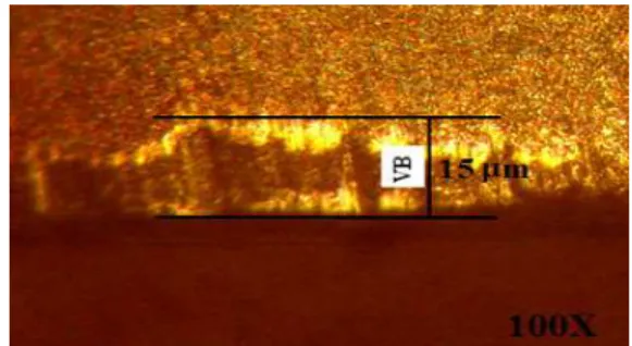
In Figure 3, the wear morphology image is evident on the edge of WC insert which is generated by cutting length under vc = 150m/min, d = 0.07 mm/rev, and doc = 0.2 mm; where the WC insert coated with [TiN/TiAlN]n multilayers (n = 200 y 300); but the [TiN/TiAlN]300
multilayers exhibit highest tribologic contribution, due to show better
mechanical properties and TiAlN surface, since these films show high hardness and present low roughness, then adhesive wear is less destructive if compared with other tribological systems, for example, uncoated WC insert. The high hardness and low roughness phenomenon contributes to a reduction of the friction coefficient. Additionally, conferring a superficial hardness that reduces the abrasive wear caused by the interaction between the coated WC insert and machined samples like AISI 4340 steel, which present hardness of 50 HRC (Oxley, 1989). Therefore, the tool life enhancement and the integrity of the cutting WC-insert coated with multilayers can also be shown by optical microscopy analysis with 100X.
First, the analysis for [TiN/TiAlN]200 coated WC inserts present
a cutting length of 11 (Km) and flank wear VBmax 15 ( m). This
revealed the behavior shown in Fig. 4. From the results obtained for the WC inserts coated with 200 layers, the results for tests run on WC inserts coated with 300 nano-bilayers are displayed in Fig. 5, These results present cutting length of 11 (Km) and flank wear of VBmax 13 ( m). As noted in Figs. 4 and 5, the curves for both coated
WC inserts correspond to the theoretical behavior of cutting tool wear due to saturation for flank wear VBmax, when cutting length
exhibits values above 9 (Km). This behavior corresponds to excessive adhesive wear characteristic for this tribologic system when the coating shows delaminating (Coelho et al., 2007). The analysis for these results (in Figs. 4 and 5) from tests conducted with similar work material and cutting conditions is shown in Table 1.
Figure 3. Worn surface of WC tool coated with [TiN/TiAlN]200.
0 2 4 6 8 1 0 1 2
4 6 8 1 0 1 2 1 4 1 6
F
la
n
k
W
e
a
r
V
B
m
a
x
(
µµµµ
m
)
C u ttin g L e n g th (K m )
W ea r v s L e n g th fo r W C in s erts c o a te d w ith [T iN /T iAlN ]200
0 2 4 6 8 10 12 4 6 8 10 12 14 F la n k W e a r V B m a x (
µµµµ
m )C utting Length (K m )
W ear vs Length for W C inserts coated w ith [TiN/TiAlN]300
Figure 5. Flank wear for WC inserts coated with 300 nano-layers machined AISI 4340 steel.
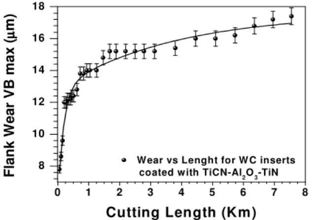
Figure 6 corresponds to measurements made at the NUMA Laboratory (USP-SC), in Brazil, with the same cutting variables, but with TiCN-Al2O3-TiN coated inserts. The TiCN-Al2O3-TiN coating
was conducted via deposition method with Sandvik Coromat® monolayers (Coelho et al., 2007). Note that the length traveled by the WC inserts coated with 200 and 300 multilayers of [TiN/TiAlN]n shows a 5000-meter increase of added work. These
coatings were made at the Center of Excellence for Novel Materials (CENM) in Cali, Colombia.
0 1 2 3 4 5 6 7 8
8 10 12 14 16 18
Wear vs Lenght for W C inserts coated with TiCN-Al2O3-TiN
F la n k W e a r V B m a x (µµµµ m )
Cutting Length (Km)
Figure 6. Flank wear for inserts coated with TiCN-Al2O3-TiN monolayers
(Coelho et al., 2007).
Figure 7 shows results obtained by Coelho et al. (2007), where it can be noted that results from inserts with (PCBN-Oxley®) substrates and different types of coatings yielded good tool life performance. When comparing the multilayered coated inserts developed at CENM to those coatings with the substrates worked on by Coelho et al. (2007), it is observed that the tool life for both systems is similar when analyzing a value of 11 (Km) for cutting length; although the latter is more expensive than the WC insert coated with our multinanolayers. For the PCBN inserts tested with different coatings like monolayered and nanostructured coatings, nano-scaled TiAlN is the coating that withstands the highest working temperature – around 900 °C (Endrino and Derflinger, 2005). In other words, the function of aluminum and titanium nitride provides a high-hardness coating with high-oxidation temperature (Endrino and Derflinger, 2005).
0 5 10 15 20 25 30
0.00 0.05 0.10 0.15 0.20 0.25 0.30 0.35 U ncoated A lC rN T iA lN T iA lN -N ano
F
la
n
k
W
e
a
r
V
B
m a x(m
m
)
C u tting le ngth (km )
Figure 7. Flank wear as a function of cutting length. Machined with vc = 150 m/min, f = 0.07 mm/rev, and h = 0.2 mm (Coelho et al., 2007).
Conclusions
In this work, the WC inserts coated with [TiN/TiAlN]300
nanostructured multilayers revealed higher tool life values than the WC inserts coated with 200 monolayers corresponding to lowest flank wear. The [TiN/TiAlN]300 multilayers show a 13% lower flank
wear than [TiN/TiAlN]200. This behavior is in relation to high
hardness and low roughness present for [TiN/TiAlN]300 multilayers.
The comparison of [TiN/TiAlN]n nanostructured multilayers
with results from other authors, including PCBN-coated WC inserts, reveals that the nanostructured multilayers have better mechanical behavior, because the adhesive wear is less destructive if compared to other tribological systems, for example the [TiN/TiAlN]300. They
exhibit a 33% lower flank wear than WC inserts coated with TiCN-Al2O3-TiN monolayers and, moreover, the [TiN/TiAlN]300
nanostructured multilayers are less expensive than the PCBN-coated ones.
Finally, the experimental development and technology used at CENM, via magnetron sputtering growth, is adequate and permits studying different deposition parameters to reach optimal deposition values. Therefore, the method correlation with measured wear demonstrated results based on optical microscopy, corresponding to experimental wear curves in cutting tools and permitted comparison with other results shown in the literature. Hence, this method is appropriate for the evaluations conducted. Furthermore, tests for physical, mechanical, and structural characterization of the coated WC inserts used in the tests reveal that such have appropriate parameter values.
Acknowledgements
This work was supported by the Center of Excellence for Novel Materials – CENM, through the CDT-ASTIN, SENA and the Thin Film Group at Universidad del Valle in Cali, Colombia, along with collaboration from the Grupo de Materiales del Departamento de Tecnología – Facultad de Ingeniería Mecánica of Inst. Sup. Politécnico José Antonio Echeverría in Cuba.
References
Bejarano, G. et al., 2008. “Mechanical and tribological properties enhancement of heat treated AISI 4340 steel by using a TiN/TiAlN multilayer coating system”. Rev. Fac. Ing. Univ. Antioquia. Vol. 44, pp. 36-42.
Braic, M. et al., 2003, “Plasma deposition of alternate TiN/ZrN multilayer hard boatings”, Journal of Optoelectronics and Advanced
Coelho, R.T. et al., 2007, “Tool wear when turning hardened AISI 4340 with coated PCBN tools using finishing cutting conditions”, Journal of
Machine Tools & Manufacture. Vol. 47, pp. 263-272.
Endrino, J.L. and Derflinger, V., 2005, “The influence of alloying elements on the phase stability and mechanical properties of AlCrN coatings”. Surface and Coatings Technology. Vol. 200, pp. 988-992.
Guo, Y.B. and Janowski, G.M., 2004, “Microstructural characterization of white layers formed during hard turning and grinding”, Transactions of
NAMRI/SME. Vol. 32, pp. 367-374.
Holleck, H., 1986, “Material selection for hard coatings”, J. Vac. Sci.
Technol., Vol. 4, pp. 2661-2666.
Komanduri, R., Chandrasekaran, N. and Raff, L.M., 2001, “Molecular dynamics simulation of the nanometric cutting of silicon”, Phil. Mag. B, Vol. 81, pp. 1989-2019.
Labdi, S. et al.,1996, “Elaboration and characterization of Ti and TiN thin films and Ti/TiN multilayers for hard coating applications”, Thin Solid
Films. Vol. 275, pp. 213-215.
Musil, J., 2000, “Hard and superhard nanocomposite coatings”, Surf.
Coat. Technol. Vol. 125, pp. 322-327.
Oxley, P.L.B., 1989, “The Mechanics of Machining: An Analytical Approach to Assessing Machinability”, Ellis Horwood, Chichester, England.
Shaw, M.C., 1984, “Mechanics of Orthogonal Cutting, Metal Cutting Principles”, Oxford University Press, London.
Usui, E., 1998, “Progress of predictive theories in metal cutting”, JSME
Int. J., Ser III. Vol. 31(2), pp. 363-369.