Croat. Chem. Acta88 (2) (2015) 171–178. http://dx.doi.org/10.5562/cca2611
Original Scientific Article
Preparation and Spectroscopic Characterization of Iron Doped Mullite
Iva Buljan,a Károly Lázár,b and Cleo Kosanovićc,*
aRuđer Bošković Institute, Bijenička c. 54,10000 Zagreb, Croatia bCentre for Energy Research, P.O.B. 49, H-1525 Budapest, Hungary cMeteorological and Hydrological Service, Grič 3, 10000 Zagreb, Croatia
RECEIVED FEBRUARY 13, 2015; REVISED APRIL 20, 2015; ACCEPTED APRIL 27, 2015
Abstract. A novel method for preparation of Fe2+/Fe3+ substituted mullite is described. Aluminosilicate
gels are applied as precursors instead of crystalline aluminosilicates as used in other common synthe-ses. The process is composed of three stages. First, iron is introduced into a homogeneous aluminosili-cate gel by ion exchange. The gel is converted to a mixture of mullite and amorphous silica in a 1263 K 3 h isothermal calcination in the the second stage. Finally, in order to obtain the nano-scale pure mulli-te phase the formed amorphous silica is removed by a dissolution in alkaline media. The components formed in various stages of the process are characterized by 57Fe Mössbauer and Fourier transform
in-fra red spectroscopies, X-ray difin-fraction method and scanning electron microscopy. Spectroscopic and diffraction methods helped the identification of the mullite phase. Mössbauer measurements revealed the presence of both Fe2+ and Fe3+ states providing a chance for perspective catalytic application of the
obtained Fe-mullite.
Keywords: iron doped mullite, SEM, 57Fe Mössbauer spectroscopy, FT-IR, XRD
1. INTRODUCTION
Mullite is a well known ceramic material. Its synthesis, properties, advantageous features and applications are described in detail e.g. in Ref. 1. One of the advanta-geous properties is its small heat expansion coefficient, thus the substance can be used as a refractory material, or e.g. as a support for catalysts in car engines which are being exposed to cyclic heat shocks.2 Mullite can
usually be formed by heating mixtures of silica- and alumina-containing appropriate precursors (minerals, oxihydroxides, etc.).3
Properties of mullite can be modified by insertion of a transition metal ion, such as iron, into the structure. Iron may occupy both octahedral and tetrahedral sites in the lattice.1 Addition of iron may promote formation of
mullite phase in high temperature phase transformati-ons.4 Insertion of iron broadens the possibilities of
per-spective applications. For instance, mullite particles can be reinforced with carbon nanotubes in a composite.5
Presence of iron is essential for the synthesis, it ca-talyses the formation of carbon nanotubes.6 In another
variation the electrical resistivity of mullite, originally an insulator, can be tuned by adding iron, thus providing a mean to prepare novel substrate materials for electro-nic devices.7 Further on, biocompatibility of
iron-containing mullite can also be utilised in various appli-cations, namely as osteoconductive substance, or as ferrimagnetic glass ceramics for hysteresis heating of surrounding tissues.8
Sol-gel processes can conveniently be used for synthesis of precursors of iron-containing mullite substances. Solution of silicic acid can be mixed with appropriate solutions of Al(NO3)3∙ 9H2O and
Fe(NO3)3∙ 9H2O,8 or further components (aluminium
isopropoxide, tetraethyl orthosilicate) can also be added to the previous constituents.7 In the subsequent stages of
preparation the gels are dried and are exposed to appro-priate high temperature thermal treatments to form the mullite structure.
Sol-gel processes are also used for synthesis of precursors of various zeolites. Several zeolites have compositions close to aluminosilicate based ceramics and their thermal treatment results in the formation of various ceramic materials.9,10 In particular, ammonium
forms of zeolite A and X are transformed to a mixture of mullite and amorphous SiO2 in a thermal treatment at
an appropriate temperature (≈ 1273 K) as demonstrated in our previous studies.11,12 The first step of the thermal
172 I. Buljan et al., Preparation and Spectroscopic Characterization of Iron Doped Mullite
formation of an amorphous aluminosilicate phase. Thus, transformation of zeolite into ceramics does not proceed directly, i.e. by „reorganisation” (rotation, translation) of specific subunits (primary and secondary building units) of zeolite framework. Instead, nucleation and crystal growth of the secondary phase (ceramic) takes place in the matrix of the amorphous aluminosilicate.10
Basically, the process of conversion of the starting gel to zeolites and later to ceramics is completed in a two-stage thermal treatment. Zeolite structure is stabili-zed at a medium temperature (≈ 773 K) first, then cera-mic is formed at ca. 1273 K. Composition of aluminosi-licate zeolites can be modified, by varying the charge compensating cations. Among other ions, iron can also be introduced to the structure in conventional processes from aqueous solutions13 or by solid state ion exchange
as well.14 Ion exchange can also be performed with
dried aluminosilicate gels, even prior to the first thermal treatment, i.e. prior to the formation of crystalline zeoli-tes. Further on, iron can also be exchanged in dried aluminosilicate gels, as has been proved with zeolite A precursors.15 It is known that mullite may crystallize at
temperatures below 1273 K by annealing amorphous precursors having high chemical homogeneity (Si-Al mixing) that can be synthesized by sol-gel or spray pyrolysis procedures.4 The homogeneity of gels and the
relatively low temperature that is required for the mulli-te preparation is the reason why such amorphous alumi-nosilicate gels were chosen to be used as precursors to prepare Fe-doped gels and in sequence synthesizing by thermal treatment Fe doped mullite. The ion exchange was performed with Fe2+ and Fe3+ ions in order to study
the possibility of producing Fe2+ or /and Fe3+ mullite
with respect to future perspective applications.
2. MATERIALS AND METHODS
2.1. Synthesis of iron mullite and amorphous SiO2
The aluminosilicate hydrogel having the molar oxide composition Na2O∙Al2O3∙2.6SiO2∙2.3H2O was
prepa-red by addition of 250 ml of sodium silicate solution (having the appropriate concentrations of Na2O and
SiO2) into a plastic beaker contained 250 ml of stirred
sodium aluminate solution (having the appropriate con-centrations of Na2O and Al2O3), at ambient temperature.
Sodium silicate solution ([Na2O] = 1.668 mol dm−3,
[SiO2] = 1.639 mol dm−3) was prepared by dissolution
of appropriate amount of sodium silicate (exsiccated technical grade anhydrous Na2SiO3; 51 wt. % Na2O, 48
wt. % SiO2; Sigma-Aldrich) in demineralised water.
Sodium aluminate solution ([Na2O] = 0.904 mol dm−3,
[Al2O3] = 0.724 mol dm−3) was prepared by dissolution
of appropriate amount of sodium aluminate (exsiccated
technical grade NaAlO2; 41 wt. % Na2O, 54 wt. %
Al2O3; Riedel-de-Haën) in demineralised water. The
prepared hydrogel was additionally stirred (for 5 min) at room temperature before the phase separation. The precipitated solid phase [amorphous Na-aluminosilicate precursor; Na-gel(A)] was separated from the liquid phase (supernatant) by centrifugation. After centrifuga-tion and removal of the supernatant, the solid phase was redispersed in demineralised water and centrifuged repeatedly. The procedure was repeated until the pH value of the liquid phase above the sediment was between 9 and 10. The washed Na-gel(A) was dried at 378 K overnight, and then was cooled down in a desic-cator over dry silicagel.
Na+ ions from the starting gel precursor were
ex-changed with NH4+ from solution as follows:
10 g of powdered gel was placed in a stainless ste-el reaction vessste-el containing 250 ml of 0.5 mol dm−3
solution of NH4Cl preheated at 343 K. The suspension
was stirred at 70 °C for 1 h, and thereafter the solid phase was separated from the solution by filtration. The residue on the filter paper was redispersed in a fresh 250 ml portion of 0.5 mol dm−3 solution of ammonium
chlo-ride and stirred again at 343 K for 1 h. The exchange and separation procedure was carried out three times in all. After final solid/liquid separation, the residue on the filter paper was rinsed with distilled water until the reaction of filtrate with AgNO3 yielded a negative result for chloride ions, and then dried at 378 K for 3 h. The exchanged gels were kept in a desiccator with saturated NaCl solution for 24 h before analyses.
The resulting gel having composition: (NH4)2O∙
Al2O3∙2.6SiO2∙2.3H2O (as determined by the chemical
analysis and TG technique) was separated into two samples. One portion was exchanged with Fe2+ cations
(10 g of NH4 gel + 250 ml of 0.025 M FeSO4 + 1 % of
NaHSO3, 1h, 343 K) and the other portion with Fe3+
cations (10g of NH4 gel + 250 ml of 0.025 M FeCl3, 343
K, 1 h). The obtained iron exchanged gel was then hea-ted isothermally at 1263 K for 3 h, in a controlled-temperature chamber furnace (ELPH-2, Elektrosanitarij) to transform to a mixture of iron-mullite and amorphous SiO2. The transition temperature was determined by
differential scanning calorimetry.
2.2. Procedure of dissolution of the amorphous SiO2
Two grams of powdered material (Fe-mullite + a-morphous SiO2 obtained by thermal treatment of
NH4,Fe-gel) dried at 378 K for 24 h was poured into a
stainless-steel reaction vessel containing 100 ml of 2 M NaOH solution preheated at 343 K (concentration of the suspension was 20 g/dm3). The reaction vessel
The reaction mixture (suspension of the powdered material in 2 M NaOH solution) was stirred with a Teflon coated magnetic bar (L = 5 cm, / = 0.95 cm) driven by a magnetic stirrer with the stirring speed of 510 r.p.m. The process was carried out for 4 h. The remained product solid phase was washed with distil-led water and dried at 378 K for 3 h.
2.3. Characterization of the Starting Materials and the Obtained Product
2.3.1. X-ray powder diffraction (XRD)
The X-ray diffraction patterns of the samples were taken by an ItalStructures APD diffractometer with GD 2000 goniometer and Cu Kα graphite radiation.
2.3.2. Fourier Transform Infrared spectroscopy (FTIR) Infrared transmission spectra of the samples were obtai-ned by the KBr wafer technique. The spectra were recorded on an FTIR Spectrometer System 2000 FT-IR (Perkin-Elmer).
2.3.3. Scanning-electron microscopy (SEM)
Scanning-electron micrographs of the samples were taken by JEOL JSM 7000F scanning-electron microsco-pe.
2.3.4. Mössbauer spectroscopy
57Fe Mössbauer spectra were collected at ambient
temperature using an in situ Mössbauer cell suitable for treatments of the samples as well. Spectra were recorded with a KFKI spectrometer, used in constant acceleration mode applying a 1 GBq Rh/57Co source.
Isomer shift values are related to metallic alpha iron, the accuracy of positional parameters is ca. ± 0.03 mm/s. Spectra were decomposed to Lorentzian shape
lines. Samples were measured consecutively in their as received state and after occasional 2 h evacuation at 643 K, and finally after a regular 2 h treatment in hy-drogen at 633K.
3. RESULTS AND DISCUSSION
Thermal treatment of the ammonium form of the alumi-nosilicate gels resulted in a mixture of mullite and SiO2,
as it was expected. Iron ions are introduced either as Fe3+ or Fe2+ from the appropriate solutions in a specific
amount that does not influence the crystallization of mullite structure. The temperature induced transforma-tions of (NH4+, Fe3+) and (NH4+, Fe2+) forms of the
amorphous aluminosilicate gel were detected by X-ray diffraction and are presented in Figures 1Aa and 1Ba.
The obtained mixtures of iron-mullite form and SiO2 were treated afterwards in alkaline solution of 2 M
NaOH for 3 h at 343 K. A great amount of SiO2 was
dissolved in the alkaline solution, the remained solids were separated and washed with distilled water. The dried samples were characterized by X-ray diffraction (see Figure 1Ba, Bb). The patterns attest that the remai-ned phase is mullite JCPDS, International Centre for Diffraction Data, 2004. :[15-776].
IR spectra were also recorded (Figure 2). Charac-teristic bands of the partially exchanged (Fe2+, NH4+)
gel and (Fe3+, NH4+) gel are shown on spectra of Figures
2Aa and 2Ba, respectively. A band at 430 cm−1 is
assig-ned to TO (T=Al, Si)16,17 bending mode, the weak broad
band in the frequency range between 510 cm−1 and 650
cm−1 with a minimum at 558−559 cm−1 is ascribed to
174 I. Buljan et al., Preparation and Spectroscopic Characterization of Iron Doped Mullite
and the band at about 830 can be assigned to the asym-metric stretching of Al−O mode.18
The bands in the region between 1000 and 1100 cm−1 are identified as Si−O−Si and Si−O−Al stretching
frequencies.16,19
The extra band on the spectra of the amorphous aluminosilicate gel that appears at 1400 cm−1 obtained
for the ion-exchanged gel with ammonium ion (Figures 2Ab, 2Bb) is assigned to the valence and deformation vibrations of the NH4+ ion.20 Characteristic bands for
mullite form appear in the spectra21 as the gel is
ther-mally treated. The recorded spectra display only the characteristic bands of mullite (Figure 2Ac, 2Bc) after dissolution. They are identified as Si−O stretching frequency in the region of 1125−1165 cm−1 as well as
in the region of 950−988 cm−1. Al−O octahedral
coordi-nation gives Al−O stretching modes in the region 500−750 cm−1 since Al−O tetahedral coordination gives
Al−O stretching modes in the region 750−850 cm−1.
According to ref. 17 we have indications for the presen-ce of both tetrahedrally and octahedrally coordinated Al−O bonds. The spectra contain a band at about 550 cm−1 indicated as an octahedral Al−O stretch and a band
430 cm−1 assigned to Si−O stretch. Bands at 3430 cm−1
are assigned to H2O, OH stretching modes and at
1635−1645 cm−1 to H2O bending modes.20 Fe2+ and Fe3+
did not effect the formation of a mullite structure. After
chemical treatment of the mixtures of both iron-mullite and amorphous SiO2 the obtained spectra contain all the
characteristic bands of mullite structure.
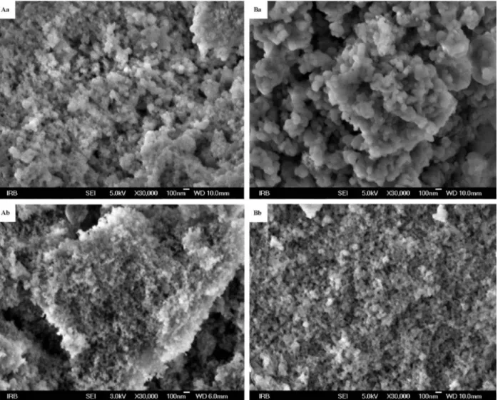
Size of particles either in the mixture of iron-mullite and SiO2 or in the final sample of iron-mullite
with minor content of SiO2 is below 100 nm as scanning
electron micrographs attest (Figure 3).
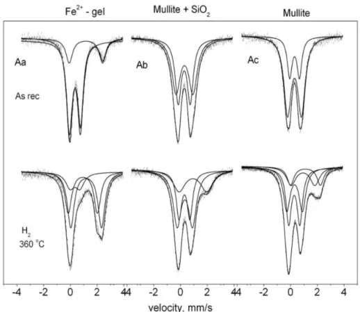
Mössbauer measurements were also performed on samples from Fe2+ and Fe3+ exchanged gel as well as
from the obtained mixtures of iron mullite and amorp-hous SiO2 and further on from the final iron mullite
after alkaline treatment. At the final stage additional reduction treatment was also performed in hydrogen to probe whether there are any accessible iron ions left for Fe3+ => Fe2+ conversion in the mullite structure formed
after the high temperature treatment. Figures 4 and 5 display the correspondig spectra for the Fe2+ and Fe3+
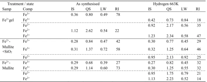
exchanged samples, data of decompositions are presen-ted in Tables 1 and 2.
The spectrum of hydrated ferrous gel consists of two doublets; one with an isomer shift (IS) of 1.12 mm s−1 and a quadrupole splitting (QS) of 2.62mm s−1
attri-buted to Fe2+ and a dominant second doublet with IS
and QS values, typical for Fe3+ in 78 % relative intensity
(RI) (Figure 4Aa). The presence of the Fe2+ doublet
the gel even after having the sample stored on air for a long period. The relative intensity of the Fe3+ doublet
decreases to 18 % on reduction with hydrogen at 633 K for 2 h, the other two doublets can be attributed to Fe2+.
This Fe3+ → Fe2+ conversion has taken place for ca. 60
% of iron, attesting that consideraby large portion of iron is accessible for conversion in the gel. (However, it should be noted that the treatment in hydrogen was performed at 633 K, structural changes might have taken place already upon heating to this temperature.) Mössbauer data recorded on the mixture of Fe-mullite and SiO2 formed upon the high temperature treatment
at 1263 K showed the presence of two doublets charac-teristic for Fe3+ (Figure 4Ab, Table 1). The obtained
IS, QS parameters for these doublets are in good corre-spondence detected earlier for Fe3+ sites in mullite.22−25
Surprisingly, reduction with hydrogen resulted still in
the presence of Fe2+ (in 25 % relative intensity). This
significantly high portion of iron was still able to un-dergo an Fe3+ => Fe2+ conversion in spite of the
previ-ous 1263 K treatment where the formation of mullite structure has already been completed. This 633 K temperature is significantly lower than the 1323 K, where the formation of carbon nano-tubes was cata-lyzed by mullite as mentioned previously.5,6 Thus, this
measurement proves that c.a. 25 % of iron ions is ac-cessible in the mullite structure and hence, it probably may take part in heterogeneous (catalytic) reactions, too. The portion of iron ions able for Fe3+ => Fe2+
conversion was increased even to 35 % by the removal of amorphous silica by dissolution in NaOH (Table 1).
In this sample presence of hematite was not detec-ted in the corresponding spectra, indicating that iron oxides and iron hydroxide are not present.
176 I. Buljan et al., Preparation and Spectroscopic Characterization of Iron Doped Mullite
Figure 4. Mössbauer spectra of the gel partially exchanged with Fe2+ (Aa), of Fe-mullite+SiO2 as synthesized (Ab), of Fe-mullite and amorphous SiO2 treated in NaOH (Ac) as well the spectra of the same samples recorded after treatment at 633 K in H2 respec-tively.
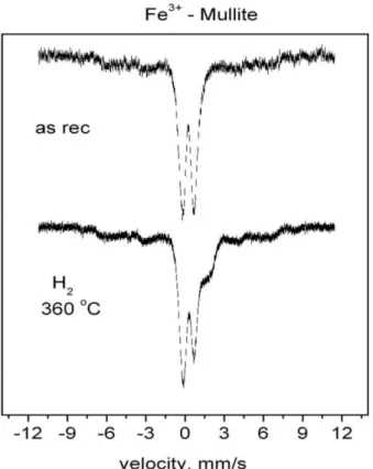
Measurements on the other series of samples, on the Fe3+ exchanged ones resulted in slightly different
spectra. The spectrum of hydrated ferric gel consists of two Fe3+ doublets (Figure 5Ba, Table 2). Reduction with
hydrogen yields the presence of both Fe2+ and Fe3+ with
very similar data as found on the previuos, Fe2+
exchan-ged sample. The feature of Fe3+ => Fe2+ reduction for a
large portion of iron upon hydrogen treatment of the mullite + SiO sample can be detected on the Fe3+
exchanged sample as well (Figure 5Bb). Presence of iron oxide in a small amount is also reflected in spectra recorded after the further stages. Namely, a shoulder appears in the spectra recorded in the 4 mm s−1
velo-city range, which show only a part of the antiferro-magnetically ordered structures exhibiting six line sextets.
The full sextet can be displayed at higher velocity range, e.g. at 12 mm s−1 (shown in Figure 6). The Table 1. Mössbauer data for gel exchanged with Fe2+ ions, then treated at 1263 K, and for the sample obtained after the dissolu-tion of the SiO2 from the thermally treated sample, afterwards
Treatment / state As synthesised Hydrogen 663K
Samp Comp IS QS LW RI IS QS LW RI
Fe3+ 0.36 0.80 0.49 78
Fe2+gel Fe3+ 0.42 0.73 0.84 18
Fe2+ 0.92 2.17 0.56 35
Fe2+ 1.12 2.62 0.54 22
Fe2+ 1.23 2.34 0.58 47
Fe2+- Fe3+ 0.28 0.84 0.47 42 0.30 0.77 0.45 29
Mullite +SiO2 Fe
3+ 0.31 1.37 0.72 58 0.32 1.25 0.64 46
Fe2+ 0.95 2.13 0.92 25
Fe2+- Fe3+ 0.29 0.68 0.39 27 0.27 0.82 0.45 32
Mullite Fe3+ 0.29 1.14 0.60 73 0.30 1.25 0.55 32
Fe2+ 0.95 1.75 0.79 21
Fe2+ 1.13 2.23 0.52 14
IS − isomer shift, mms−1, QS − quadrupole splitting, mms−1, LW – line width mms−1, RI – relative intensity, spectral area %.
Table 2. Mössbauer data for gel exchanged with Fe3+ ions, then treated at 1263 K and for the sample obtained after the dissolution of the SiO2 from the thermally treated sample afterwards
Treatment / state As received Hydrogen 663K
Samp Comp IS QS LW RI IS QS LW RI
Fe3+ 0.35 0.62 0.32 47
Fe3+gel Fe3+ 0.43 0.76 0.63 17
Fe3+ 0.35 1.00 0.41 53
Fe3+
Fe2+ 0.99 1.60 0.52 22
Fe2+ 0.96 2.24 0.43 31
Fe2+ 1.20 2.34 0.46 30
Fe3+- Fe3+ 0.27 0.75 0.41 27
Mullite Fe3+ 0.29 1.23 0.57 33 0.27 0.93 0.56 35
+SiO2 (*) Fe3+ ( "magn. oxide") "n/d" "n/d" "n/d" ≈ 40 "n/d" "n/d" "n/d" ≈ 40
Fe2+ 0.76 1.47 0.81 15
Fe2+ 1.04 2.01 0.54 10
Fe3+- Fe3+ 0.27 0.75 0.42 28
Mullite (*) Fe3+ 0.28 1.24 0.50 22 0.27 0.95 0.55 31
Fe3+ ("magn. oxide") "n/d" "n/d" "n/d" ≈ 50 "n/d" "n/d" "n/d" ≈ 50
Fe2+ 0.83 1.40 0.73 12
Fe2+ 1.01 2.08 0.44 7
178 I. Buljan et al., Preparation and Spectroscopic Characterization of Iron Doped Mullite
sextet of oxide has a low intensity, appearing only in form of shoulders in the base line.
4. CONCLUSION
Procedure of the preparation of Fe2+/Fe3+ substituted
mullite is described in this study using aluminosilicate gel as starting material. The main idea to use amorp-hous aluminosilicate gel was based on the feature of the amorphous aluminosilicate gels that they can be used as precursors for the synthesis of zeolites and that they have the ability to exchange their cations with the cations from a solution as well as the crystalline zeoli-tes. Usage of ammonium form of such gels was prefer-red due to its temperature induced transformation to a mixture of mullite and SiO2. Sodium was exchanged
for ammonium in the first stage, then ammonium was exchanged partly for iron in a second ion exchange. Mixture of mullite and silica formed upon calcination, the latter component was removed by dissolution. The stages of processes were followed by 57Fe Mössbauer
spectroscopy, Fourier transform infra red spectrosopy
and scanning electron microscopy for confirmation of incorporation of Fe2+ or /and Fe3+ into the mullite
structure and demonstrating thereby a novel method for the preparation of iron substituted mullites.
REFERENCES
1. H. Schneider, J. Schreuer, and B. Hildmann, J. Eur. Ceram. Soc.
28 (2008) 329−344.
2. P. Oikonomou, Ch. Dedelouis, C. J. Stournaras, and C. Ftikos, J. Eur. Ceram. Soc.27 (2007) 3475−3482.
3. C. Sadik, I. El Amrani, and A. Almizane A., Mater. Sci. Appl.4 (2013) 337−346.
4. A. Ocaña, A. Caballero , T. González-Carrenõ, and C. J. Serna, Mater. Res. Bull.35 (2000) 775−788.
5. A. Weibel, A. Peigney, G. Chevallier , C. Estournes, and C. Lau-rent, Ceram. Int.39 (2013) 5513−5519.
6. V. G. De Resende, X. Hui, C. Laurent, A. Weibel, E. De Grave, and A. Peigney, J. Phys. Chem. C113 (2009) 11239−11245. 7. D. Roy, K. Haldar, B. K. Paul, A. Bhattacharya, S. Das, and P.
Nandy, J. S. E. M. A. T.3A (2013) 11−17.
8. S. Simon, M. Tămăşan, T. Radu, and V. Simon, Eur. Phys. J. Appl. Phys.55 (2011) 30401−30405.
9. M. A. Subramanian, D. R. Corbin, and U. Chowdhry, Bull. Ma-ter. Sci. 16 (1993) 665−668.
10. C. Kosanović and B. Subotić, Micropor. Mesopor. Mat. 66 (2003) 311−319.
11. C. Kosanović, B. Subotić, and I. Šmit, Thermochim. Acta317 (1998) 25−37.
12. C. Kosanović, B. Subotić, and A. Ristić, Croat. Chem. Acta 75 (2002) 783−792.
13. S. Kameoka, T. Suzuki, K. Yuzaki, T. Takeda, S. Tanaka, S. Ito, T. Miyadera, and K. Kumimori, Chem. Comm. 1 (2000) 45−46. 14. K. Lázár, G. Pál-Borbély, H. K. Beyer, and H. G. Karge, J.
Chem. Soc. Faraday Trans. 9 (1994) 1329−1334.
15. C. Kosanovic, S. Bosnar, B. Subotic, K. Lázár, N. Novak Tušar, N. Tomašić, and Z. Kajcsos, Stud. Surf. Sci .Catal.174 (2008) 929−932.
16. E. M. Flanigen, H. Khatami, and H. A. Szymanski, Infrared Structural Studies of Zeolite Frameworks, in: R. F. Gould (edi-tor), Molecular Sieve Zeolites – I, Advances in Chemistry Series, Vol. 101, Washington DC: American Chemical Society; 1971, pp. 201−227.
17. P. Padmaja, G. M. Anilkumar, P. Mukundan, G. Aruldhas, and K. G. K. Warrier, Int. J. Inorg. Mater.3 (2001) 693−698. 18. X. H. Jin, L. Gao, and J. K. Guo, J. Eur. Ceram. Soc.22 (2002)
1307−1311.
19. K. J. D. MacKenzie, J. Am. Ceram. Soc.55 (1972) 68−71. 20. O. V. Bulgakov and T. V. Antipina, Zh. Prikl. Spektr. 14 (1971)
412−417.
21. D. Voll, A. Beran and H. Schneider, J. Eur. Ceram.18 (1998) 1101−106.
22. J. Parmentier, S. Vilminot, and J. L. Dormann, Solid State Sci.1 (1999) 257−265.
23. C. M. Cardile, I. W. M. Brown, and K. J. D. Mackenzie, J. Ma-ter. Sci. Lett. 6 (1987) 357−362.
24. K. J. D. MacKenzie, Spectroscopy of Mullite and Compounds with Mullite-related Structures, in: H. Schneider and S. Komar-neri (Eds.), Mullite, Wiley-VCH, New York, 2005, pp. 210−215. 25. D. E. Mack, K. D. Becker, and H. Schneider, Am. Mineral. 90
(2005) 1078−1083. Figure 6. Mössbauer spectra of Fe3+ exchanged mullite + SiO2