COMPARATIVE ANALYSIS OF STEEL AND ALUMINUM STRUCTURES
Professional paper / Stručni rad
Josip Peko
University of Split, Faculty of Civil Engineering, Architecture and Geodesy, mag.ing.aedif.
Corresponding author: [email protected]
Neno Torić
University of Split, Faculty of Civil Engineering, Architecture and Geodesy, Assistant Professor
Ivica Boko
University of Split, Faculty of Civil Engineering, Architecture and Geodesy, Full Professor
Abstract: This study examined steel and aluminum variants of modern exhibition structures in which the main design requirements include low weight (increased span/depth ratio, transportation, and construction) and durability (resistance to corrosion). This included a design situation in which the structural application of aluminum alloys provided an extremely convenient and practical solution. Viability of an aluminum structure depends on several factors and requires a detailed analysis. The overall conclusion of the study indicated that aluminum can be used as a structural material and as a viable alternative to steel for Croatian snow and wind load values and evidently in cases in which positive properties of aluminum are required for structural design. Furthermore, a structural fire analysis was conducted for an aluminum variant structure by using a zone model for realistic fire analysis. The results suggested that passive fire protection for the main structural members was not required in the event of areal fire with duration of 60 min.
Keywords: aluminum alloys, structures, design, fire, steel, aluminum
USPOREDNA
ANALIZA ČELIČNE I AL
UMINIJSKE KONSTRUKCIJE
Sažetak: U radu su prikazane čelična i aluminijska inačica suvremene konstrukcije izložbenog centra za koju je prioritet kod projektiranja bila mala masa (povećanje omjera raspon/visinarešetke, transport, montaža) i trajnost (otpornost na koroziju). To je samo jedna od projektnih situacija u kojima konstrukcijska primjena aluminijskih legura daje vrlo prikladno i praktično rješenje. Samo pitanje isplativosti aluminijske inačice ovisi o više faktora i zahtijeva detaljniju analizu. Opći zaključak je da se, s obzirom na hrvatske vrijednosti opterećenja snijegom i vjetrom i, naravno, za konstrukcije kod kojih se traže pozitivna svojstva aluminija, aluminij može koristiti kao alternativni konstrukcijski materijal u odnosu na čelik.Također, za aluminijsku inačicu konstrukcije provedena je analiza požara, koristeći pritom model zona za analizu realnog požara. Rezultati pokazuju da za realan požar u trajanju od 60 minuta nije potrebna pasivna protupožarna zaštita za glavne konstrukcijske elemente.
1
INTRODUCTION
Aluminum (Al) was discovered 200 years ago. Following an initial period involving technological developments, aluminum alloys are used in several areas of construction including the structural engineering industry. Theoretical and experimental studies performed over the recent decades analyzed the structural behavior of extruded and welded aluminum members. A solid foundation of modern standardization involves previously acquired knowledge as a precondition for the application of aluminum in practice [1].
It is important to note that aluminum is the only lightweight metal that is used in load-bearing structures in structural engineering [2].
2
ALUMINIUM ALLOYS FOR STRUCTURAL APPLICATIONS
2.1 General characteristics
Aluminum alloys are typically considered as economical and therefore competitive in applications involving the following conditions [1]:
a) Lightness: Aluminum alloys have a low specific weight (one third that of steel) that allow for the following: - Simplification of the erection phases;
- Transportation of fully prefabricated components; - Reduction of the loads transmitted to foundations;
- Economization of energy either during erection and/ or in service; - Reduction of physical labor.
b) Corrosion resistance: the formation of a protective oxide film on the surface makes the following possible: - Reduction of maintenance expenses;
- Ensuring of a good performance in corrosive environments.
c) Functionality of structural shape: The extrusion process makes the following possible:
- Improvements in the geometrical properties of a cross-section by designing a shape that simultaneously provides minimum weight as well as highest structural efficiency;
- Obtaining stiffened shapes without using built-up sections, and thus avoiding welding or bolting; - Simplification of connecting systems between different components, and thereby improving joint details; - Combining different functions of the structural component, and thus achieving more economical and
rational profiles.
2.2 Aluminum and its alloys
The properties of aluminum that have a positive influence on its use in construction include the following [2]: - It is 2.9 times lighter than steel (Table 1);
- It possesses good mechanical properties (including toughness) at low temperatures; - It exhibits good reflectivity with respect to light and heat;
- It is non-toxic and does not have a negative impact on the environment;
- It possesses good corrosion resistance due to the natural protection layer of oxide; - It is not magnetic;
- It does not involve arcing in the processing.
The properties of aluminum that have a negative influence on its use in construction include the following [2]: - High cost of production;
- High deformability (the Young's modulus is thrice that of steel) (Table 1); - High sensitivity to the problems of stability;
Table 1 Comparison of the basic physical properties of aluminum alloys with respect to steel [2]
Physical properties/ Metal Aluminum alloys Steel
Melting point 660 C 1425 – 1540 C
Density at 20C 2700 kg/m3 7850 kg/m3
Thermal elongation 23∙10-6C-1 12∙10-6C-1
Specific heat ~ 920 J/kgC ~ 440 J/kgC Thermal conductivity ~ 240 W/mC ~ 54 W/mC Elasticity modulus 70 000 N/mm2 210 000 N/mm2
Shear modulus 27 000 N/mm2 81 000 N/mm2
Poisson's ratio 0.3 0.3
3
FIELD OF APPLICATION
The most purposeful application of aluminum as a building material is possible in cases in which it is necessary to reduce building and maintenance costs, and this can be achieved by utilizing the basic properties of aluminum, namely lightness, corrosion resistance, and functionality.
The structural applications that best fit these properties in the field of structural engineering include the following [1]:
a) Long-span roof systems in which live loads are small when compared with dead loads as in the case of reticular space structures and geodetic domes covering large span areas such as halls and auditoriums.
b) Structures located in inaccessible places that are far from a fabrication shop in which transport economy and ease of erection are extremely important such as electrical transmission towers that can be transported by a helicopter.
c) Structures situated in corrosive or humid environments such as swimming pool roofs, river bridges, hydraulic structures, and offshore super-structures.
d) Structures with moving parts, such as sewage plant crane bridges and moving bridges, in which lightness corresponds to economy of power under service.
e) Structures for special purposes in which the performance of maintenance operations is particularly difficult and must be limited such as cases of masts, lighting towers, antennas towers, and sign motorway portals. The utilization of aluminum presents a valid alternative to steel when structural weight is a fundamental issue. Additionally, the complete absence of maintenance costs increases advantages, especially with respect to structures that are situated in humid environments [1].
An application and a historic debut in this area included the reticular space structure of the Interamerican Exhibition Centre in Sao Paolo (Brazil) that was constructed in 1969 (Figures 1–6).
The original structure (Figures 1–6) covers an area of approximately 67 600 m2 with a 60 x 60 m mesh. The
depth of the reticular layer corresponded to 2.36 m and the total height of the structure corresponded to 16.36 m.
The structure was completely site-bolted on the ground (Figure 2) and afterwards lifted to the final level of 14 m by means of 25 cranes located in the corners of the mesh (Figure 3) at the positions of the structure supports. The weight of the reticular structure, the number of bars, and the total length of the bars corresponded to 16 kg/m2,
56 820, and 300 km, respectively. The erection time was extremely high (27 h) and included 550 000 bolts at 13724 nodes. The materials included aluminum alloys of AW 6063 and AW 6351 series T6 for cylindrical bars, Al 99.5 for trapezoidal sheeting, and galvanized steel bolts for connections.
Figure 2 Trusses bolted on the ground [3]
Figure 3 Structure lifted at the final level [3]
Figure 4 The finished structure [3]
Figure 6 Bolted connections of column branches [3]
4
STRUCTURAL DESIGN OF THE INTERAMERICAN EXHIBITION CENTER IN SAO PAULO
(BRAZIL)
This extraordinary structure is the subject of this paper. The idea involved using the concept of construction of the Brazil exhibition center to analyze the aluminum and steel variants of this structure for Croatian snow and wind load conditions and to finally provide an answer with respect to the competitiveness of the structure in steel and aluminum variants.
4.1 Construction model
All calculations and checks were based on previous studies [4-6] and performed using the software Nemetschek Scia Engineer 2013.1 [7].
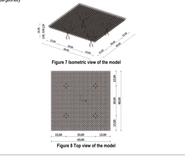
4.1.1 Model geometry
Figure 7 Isometric view of the model
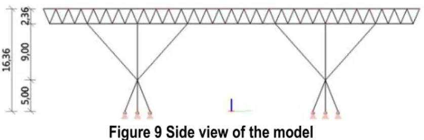
Figure 9 Side view of the model
The main dimensions of the structure (Figures 7–9) included the following: truss length: 15 + 30 + 15 = 60 m; truss height: 2.36 m; number of columns: 4; distance between columns: 30 m; height of columns: 5 + 9 = 14 m; clear height of the structure: 14 m; and total height of the structure: 14 + 2.36 = 16.36 m.
4.1.2 Boundary conditions
All elements within the structure model were modeled as truss elements, and this implied that they were only capable of transmitting an internal axial force. Buckling length for each of elements was equal to the system length of the element.
4.2 Loads and load combinations
The loads were calculated according to Eurocodes [8-10] and the specific location of the structure (Croatia, Dugopolje, latitude: 43.58; longitude: 16.60; and altitude: 295 m). All loads were applied as concentrated forces at the nodes of the upper flange of the truss. The load values were as follows:
- Self weight: g taken into account by software (ρAl = 2700 kg/m3);
- Additional gravity load (claddings and installations): dg = 0.40 kN/m2;
- Snow: s = 0.32 kN/m2;
- Wind (terrain cat. II, basic wind velocity vb,0 = 25 m/s, cpe,max/ cpe,min= 0.7/ -1.2, cpi,max/ cpi,min = 0.2/ -0.3):
qp (z) = 1.04 kN/m2 (pressure wind w1 and suction wind w2were considered).
The load combinations (ULS and SLS) were automatically provided by the software Nemetschek Scia Engineer 2013.1 [7].Both variants included the critical ULS combination of 1.35∙g+1.35∙dg+0.75∙s+1.50∙w1 and the
corresponding SLS combinations of1.00∙g+1.00∙dg+0.50∙s+1.00∙w1.
4.3 Aluminum variant
The aluminum alloy EN - AW 6082 T6 was selected in the study because of its high strength value (as shown in Table 2) and its procurement availability in the form of the chosen profiles (as shown in Table 3).
Table 2 Mechanical properties of the selected aluminum alloy
Physical properties/ Al alloy EN - AW 6082 T6
0.2% proof strength fo 260 N/mm2 Ultimate tensile strength fu 310 N/mm2
Buckling class A
All the profiles (Table 3) for the chosen aluminum alloy were obtained from the website of a vendor "BLECHA" [11].
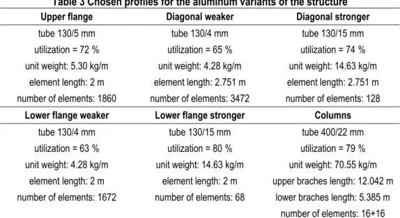
Table 3 Chosen profiles for the aluminum variants of the structure
Upper flange Diagonal weaker Diagonal stronger
tube 130/5 mm tube 130/4 mm tube 130/15 mm
utilization = 72 % utilization = 65 % utilization = 74 % unit weight: 5.30 kg/m unit weight: 4.28 kg/m unit weight: 14.63 kg/m
element length: 2 m element length: 2.751 m element length: 2.751 m number of elements: 1860 number of elements: 3472 number of elements: 128
Lower flange weaker Lower flange stronger Columns
tube 130/4 mm tube 130/15 mm tube 400/22 mm
utilization = 63 % utilization = 80 % utilization = 79 % unit weight: 4.28 kg/m unit weight: 14.63 kg/m unit weight: 70.55 kg/m
element length: 2 m element length: 2 m upper braches length: 12.042 m number of elements: 1672 number of elements: 68 lower braches length: 5.385 m
number of elements: 16+16
Section through lower flanges of the truss Section through diagonals of the truss
Side view of the model Section through column branches
Figure 10 Disposition of profiles in the structural model
The total mass is given as follows:
1860 5.30 2 3472 4.28 2.751 128 14.63 2.751 1672 4.28 2 68 14.63 2
16 70.55 12.042 16 70.55 5.385 101.72 tot
m
t
(1)
The mass per m2 is given as follows:
m = mtot / 602≈28 kg/m2 (2)
Displacements for SLS combination: uz, max = 98.7 mm < l/150 = 100 mm; ux, y, max = 44.5 mm < H/300 = 54.5
4.4 Steel variant
Steel grade S355 was used as the steel variant given that it has a value of yield strength comparable to the chosen aluminum alloy (as shown in Table 2).
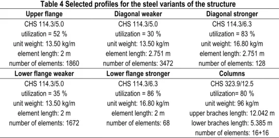
Table 4 Selected profiles for the steel variants of the structure
Upper flange Diagonal weaker Diagonal stronger
CHS 114.3/5.0 CHS 114.3/5.0 CHS 114.3/6.3
utilization = 52 % utilization = 30 % utilization = 83 % unit weight: 13.50 kg/m unit weight: 13.50 kg/m unit weight: 16.80 kg/m
element length: 2 m element length: 2.751 m element length: 2.751 m number of elements: 1860 number of elements: 3472 number of elements: 128
Lower flange weaker Lower flange stronger Columns
CHS 114.3/5.0 CHS 114.3/6.3 CHS 323.9/12.5
utilization = 35 % utilization = 86 % utilization= 80 % unit weight: 13.50 kg/m unit weight: 16.80 kg/m unit weight: 96 kg/m
element length: 2 m element length: 2 m upper braches length: 12.042 m number of elements: 1672 number of elements: 68 lower braches length: 5.385 m
number of elements: 16+16
In order to ensure the aesthetics of the construction soffit, all the selected truss members had equal diameters not exceeding 5 mm due to technical requirements of welding thickness. These reasons led to the lower utilization of a few profiles (as shown in Table 4).
Dispositions of weaker and stronger profiles in the structure were identical to that of the aluminum variant (Figure 10).
The total mass is as follows:
1860 13.50 2 3472 13.50 2.751 128 16.80 2.751 1672 13.50 2 68 16.80 2
16 96 12.042 16 96 5.385 259.28 tot
m
t
(3)
The mass per m2 is as follows:
m = mtot / 602≈72 kg/m2 (4)
Displacements for the SLS combination included the following: uz, max = 42.3 mm < l/150 = 100 mm; ux, y, max = 18.6
mm < H/300 = 54.5 mm.
5
STRUCTURAL FIRE ANALYSIS OF THE ALUMINIUM STRUCTURE
5.1 Input parameters and assumptions
The dimensions of the fire compartment were as follows: - width: 60 m;
- length: 60 m; - clear height: 14 m;
- total height: 14 + 2.36 = 16.36 m;
- the total area of openings on each side: 0.10∙60∙16.36 = 98.16 m2;
- medium height of the openings: 3 m.
The roof and facade panels are 100 mm thick with rock wool. The physical properties were as follows: - density: ρ = 100 kg/m3;
- specific heat: c = 840 J/kgK;
- thermal conductivity: λ = 0.038 W/mK.
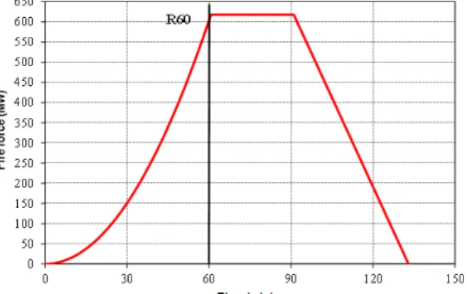
The characteristic fire load density was selected with respect to the exhibition purpose of the structure given a value of qf,k = 730 MJ/m2(Table E.4 [12]). The fire resistance was required for 60 min (R60), and this assumed that
Simulation of a real fire was based on the assumption that the overall fire load was consumed such that in the growth, flashover, and complete development stage of the fire, the fire load consumed corresponded to approximately 70% of the initial fire load value, and the remaining 30% was consumed in the decay stage (Figure 11).
Figure 11 Fire force curve for all three phases of fire action
5.2 Enclosure fire temperature
Based on the input parameters, a software package "JET" [13] was used to conduct a simulation of a real fire to provide the temperature-time relationship (as shown in Figure 12) in the fire compartment. Figure 12 also shows a standard fire curve (ISO 834) to compare the zone model predictions with the ISO fire temperatures.
Figure 12 The curves of real and standard fires (ISO 834)
5.3 Temperature in members
A “1D HEAT” [14] was used to calculate member temperature in a one dimensional transient nonlinear heat transfer model. The selected resultant emissivity was 0.70, and it corresponded to the colored surface of aluminum covered with soot.
The remaining coefficients in the heat transfer equation were based on an extant study [12].
The term “1D HEAT“ [14] accounted for the linear variation of specific heat as a function of member temperature and was based on a heat capacity model in a previous study [15] as follows:
cAl = 0.41∙θAl + 903 (J/kg⁰ C) (5)
As an input in “1D HEAT” [14] model the realistic temperature-time history of the compartment temperature is approximated by a 2nd degree polynomial:
y = 0.00039∙x2 + 2.89169∙x + 25.55042 (6)
Figure 13 Temperature value sand reduction factors [15] for member 130/4 mm
Figure 14 Temperature values and reduction factors [15] for member 130/5 mm
Figure 15 Temperature values and reduction factors [15] for member 130/15 mm
5.4 Capacity and stability check
With respect to the calculation model for capacity check, the obtained member temperatures were applied on the affected members, and the mechanical properties (E, fo, fu) were reduced accordingly. With respect to the fire
exposure scenario, it was necessary to check the capacity and stability of structural components for actions corresponding to the accidental design situation as follows: 1.0∙g + 1.0∙dg + 1.0∙T (specifically, g denotes dead weight; dg denotes additional dead load; T denotes temperature load).
A cross section classification was performed as for normal temperature exposure [15]. Tensile and compression load capacity are calculated as follows [15]:
, , o, / ,
fi Rd Rd Mx M fi
N k N
(7)
Buckling capacity of the member is calculated as follows [15]:
, ,t, , , 1/ 1.2 ,
b fi Rd o b Rd M M fi
N k N (8)
where:
ko, Θdenotes the reduction factor for effective 0.2% proof strength at temperature Θ based on a previous study [15];
NRd denotes the design resistance for normal temperature design based on a previous study [4]. NRd is either
No,Rd or Nu,Rd;
No,Rd denotes general yielding along the member based on a previous study [4]; and Nu,Rd denotes local failure
at a section with HAZ based on a previous study [4];
Nb,Rd denotes the buckling resistance for normal temperature design based on a previous study [4];
Mx
denotes the material coefficient based on a previous study [4], andM1 is used in combination with No,Rd
and M2 is used in combination with Nu,Rd; , 1.0
M fi
denotes the partial safety factor for the mechanical properties of aluminum for a fire situation based on a previous study [16];1.2 corresponded to a reduction factor of the design resistance due to the temperature dependent creep of aluminum alloys based on a previous study [15].
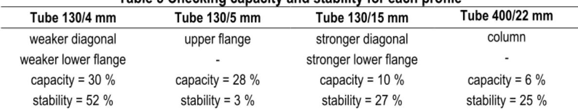
All calculations and checks (Table 5) were based on a previous study [15] and performed using the Nemetschek Scia Engineer 2013.1software [7].
Table 5 Checking capacity and stability for each profile
Tube 130/4 mm Tube 130/5 mm Tube 130/15 mm Tube 400/22 mm
weaker diagonal upper flange stronger diagonal column
weaker lower flange - stronger lower flange -
capacity = 30 % capacity = 28 % capacity = 10 % capacity = 6 % stability = 52 % stability = 3 % stability = 27 % stability = 25 %
The overall conclusion of the conducted structural fire analysis was passive fire protection was not necessary for structural members. This was due to the low compartment fire temperatures that induced very low temperatures in the structural members.
6
CONCLUSION
This study presented a practical application of aluminum in the case of modern building design involving low weight design priority (that is, increased span/depth ratio, transportation, and installation) and durability (resistance to corrosion).
The masses of the aluminum and steel variants of the considered structure corresponded to 28 kg/m2 and 72
kg/m2, respectively. The initially higher price of the aluminum variant did not necessarily indicate a higher price for
of the structural design and involved issues of stability and fire resistance that were not adequately researched to-date. Although it is not possible to accurately identify the more cost-effective material, it was concluded that aluminum could compete with steel for the specific conditions involving snow and wind load considered in this study. This was evident in the three-fold reduction in the required mass for the aluminum structure.
REFERENCES
[1] Mazzolani, F. M. 2006: Structural Applications of Aluminium in Civil Engineering, Structural Engineering International (SEI), Journal of the IABSE, 16 (4), pp. 280-285.
[2] Skejić, D., Boko, I., Torić, N. 2015: Aluminium as a material for modern structures, Građevinar, 67 (11), pp. 1075-1085, https://dx.doi.org/10.14256/JCE.1395.2015
[3] Mazzolani, F. M. 2008: : Aluminium Alloy Structures: Fields of Application, Bruxelles
[4] HRN EN 1999-1-1, Eurocode 9: Design of aluminium structures – Part 1 – 1: General structural rules (EN 1999-1-1:2007)
[5] HRN EN 1993-1-1, Eurocode 3: Design of steel structures – Part 1 – 1: General rules and rules for buildings (EN 1993-1-1:2005+AC: 2009)
[6] HRN EN 1993-1-1:2014/NA, Eurocode 3: Design of steel structures – Part 1 – 1: General rules and rules for buildings – National Annex
[7] Official web page of the software “Nemetschek Scia Engineer“ (https://www.scia.net/en/support/downloads), Accessed 1June 2016.
[8] HRN EN 1991-1-3:2012/NA, Eurocode 1: Actions on structures–Part 1–3: General actions–Snow loads – National Annex
[9] HRN EN 1991-1-4:2012/NA, Eurocode 1: Actions on structures–Part 1–4: General actions–Wind actions– National Annex
[10] HRN EN 1991-1-4, Eurocode 1: Actions on structures – Part 1–4: General actions – Wind actions (EN 1991-1-4:2005+AC:2010+A1:2010)
[11] Web page of the manufacturer “BLECHA“ ( http://www.aluprofil.at/hr/standardni-profili-trgovacki-profili/program-isporuke/), Accessed 1 June 2016.
[12] HRN EN 1991-1-2, Eurocode 1: Actions on structures – Part 1 – 2: General actions – Actions on structures exposed to fire (EN 1991-1-2:2002+AC:2009)
[13] The zone fire model JET: A model for the prediction of detector activation and gas temperature in the presence of a smoke layer (http://fire.nist.gov/bfrlpubs/fire99/art033.html), Accessed 14 June 2016.
[14] Boko, I., Torić, N., Peroš, B. 2012: Analysis of heat transfer design models based on EN 1993-1-2, Građevinar, 64 (4), pp. 285-292, http://hrcak.srce.hr/file/121592
[15] HRN EN 1999-1-2, Eurocode 9: Design of aluminium structures – Part 1 – 2: Structural fire design (EN 1999-1-2:2007)
![Table 1 Comparison of the basic physical properties of aluminum alloys with respect to steel [2]](https://thumb-eu.123doks.com/thumbv2/123dok_br/18150643.327547/3.892.147.744.149.351/table-comparison-basic-physical-properties-aluminum-alloys-respect.webp)
![Figure 3 Structure lifted at the final level [3]](https://thumb-eu.123doks.com/thumbv2/123dok_br/18150643.327547/4.892.145.773.408.1141/figure-structure-lifted-final-level.webp)
![Figure 13 Temperature value sand reduction factors [15] for member 130/4 mm](https://thumb-eu.123doks.com/thumbv2/123dok_br/18150643.327547/10.892.125.765.117.912/figure-temperature-value-sand-reduction-factors-member-mm.webp)