Sedimentology and sequence stratigraphy of the Bryne
and Lulu Formations, Middle Jurassic, northern Danish
Central Graben
Jan Andsbjerg
The Middle Jurassic Bryne and Lulu Formations of the Søgne Basin (northern part of the Danish Central Graben) consist of fluvially-dominated coastal plain deposits, overlain by interfingering shoreface and back-barrier deposits. Laterally continuous, mainly fining-upwards fluvial channel sandstones that locally show evidence for tidal influence dominate the alluvial/coastal plain deposits of the lower Bryne Formation. The sandstones are separated by units of fine-grained floodplain sediments that show a fining-upwards – coarsening-upwards pattern and locally grade into lacustrine mudstones. A regional unconformity that separates the lower Bryne Formation from the mainly estuarine upper Bryne Formation is defined by the strongly erosional base of a succession of stacked channel sandstones, interpreted as the fill of a system of incised valleys. Most of the stacked channel sandstones show abundant mud laminae and flasers, and rare her-ringbone structures, suggesting that they were deposited in a tidal environment, probably an estu-ary. Several tens of metres of the lower Bryne Formation may have been removed by erosion at this unconformity. The estuarine channel sandstone succession is capped by coal beds that attain a thickness of several metres in the western part of the Søgne Basin, but are thin and poorly developed in the central part of the basin. Above the coal beds, the Lulu Formation is dominated by various types of tidally influenced paralic deposits in the western part of the basin and by coarsening-upwards shoreface and beach deposits in central parts. Westwards-thickening wedges of paralic deposits interfinger with eastwards-thickening wedges of shallow marine deposits.
The Middle Jurassic succession is subdivided into nine sequences. In the lower Bryne Formation, sequence boundaries are situated at the base of laterally continuous fluvial channel sandstones whereas maximum flooding surfaces are placed in laterally extensive floodplain or lacustrine mud-stones. The unconformity that separates the alluvial plain deposits of the lower Bryne Formation from the estuary deposits of the upper Bryne Formation is interpreted as a sequence boundary that bounds a system of incised valleys in the western and southern parts of the basin. Sequence boundaries in the Lulu Formation are situated at the top of progradational shoreface units or at the base of estuarine channels. Maximum flooding surfaces are located within marine or lagoonal mudstone units. Marine highstand deposits are partitioned seawards, in the eastern part of the basin, whereas paralic transgressive deposits are partitioned landwards, in the west. This marked sediment partitioning in the uppermost part of the succession resulted from the alternation of episodes of fault-induced half-graben subsidence with periods of slow uniform subsidence.
Keywords: Danish Central Graben, Middle Jurassic, Bryne Formation, Lulu Formation, sedimentology, sequence stratigraphy, alluvial/coastal plain – shallow marine, sediment partitioning
During the Middle Jurassic, the North Sea area was dominated by extensive coastal plain, delta plain and shallow marine environments. The resultant deposits have been described from the Viking Graben (Graue
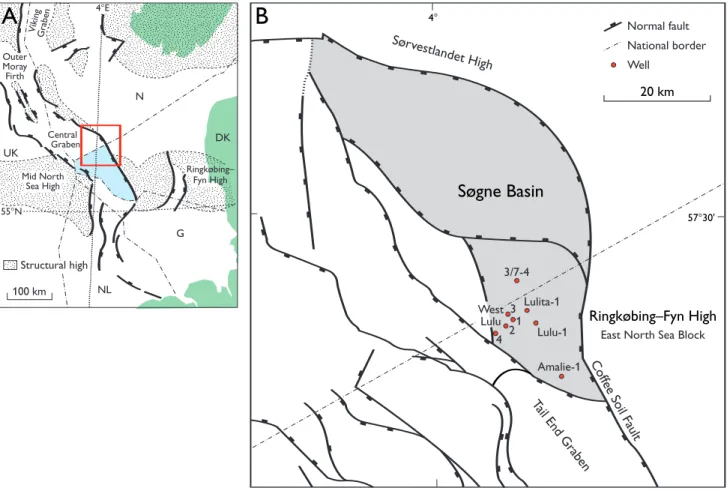
et al.1987), from the Moray Firth and the Yorkshire coast along the western margin of the North Sea Basin (Hancock & Fisher 1981; Rawson & Wright 1995; Stephen & Davies 1998), from the Norwegian–Danish Basin along the eastern margin (Nielsen 2003, this volume), and from the Central Graben in the central and south-ern North Sea (Gatliff et al.1994; Herngreen et al.2003, this volume; Fig. 1). In the past two decades, several minor gas, condensate and oil fields with Middle Jurassic reservoirs have been discovered in the Søgne Basin, a minor sub-basin straddling the Danish–Norwegian boundary line along the eastern main boundary fault of the Central Graben. Production from these fields has started recently.
The aims of this paper are threefold: (1) to provide a detailed environmental interpretation of characteristic
sedimentary facies of the Middle Jurassic rocks and estab-lish their palaeogeographic relationships; (2) to estabestab-lish a high resolution sequence stratigraphic framework for the Middle Jurassic succession in the Søgne Basin of the Danish Central Graben; and (3) to describe and inter-pret the important reservoir rocks in the upper part of the Middle Jurassic succession, their complex inter-rela-tionships and their relationship to surrounding rocks, and the processes that caused such complexities.
Regional setting and structural
development
The Danish Central Graben forms part of the Central Graben (Fig. 1), a complex N–S-trending Mesozoic intra-cratonic rift basin. Subsidence of the Danish Central Graben was initiated in the Triassic but was most active during the Middle and Late Jurassic (Møller 1986). The Central Graben separates the Mid North Sea High to the
■ ■ ■ ■ ■ ■ ■■ ■ ■ ■■ ■■ ■■ ■■ ■■ ■■ ■ ■ ■ ■ ■ ■ ■■ ■■ ■■ ■■ ■ ■ ■■ ■ ■ ■ ■ ■ ■ ■ ■ ■ ■ ■ ■ ■■ ■■ 55°N
4°E
100 km Structural high Outer Moray Firth VikingGraben Central Graben Ringkøbing– Fyn High N G NL UK DK Mid North Sea High Normal fault National border Well ■ ■ ■ ■ ■ ■ ■ ■ ■ ■ ■ ■ ■■ ■ ■ ■ ■ ■■ ■ ■ ■ ■ ■ ■ ■■ ■ ■ ■ ■ ■■ ■■ ■■ ■■ ■ ■ ■ ■ ■ ■ ■■ ■■ ■ ■ ■ ■ ■ ■ ■ ■ ■ ■ ■ ■ ■ ■ ■ ■ ■ ■ ■■ ■ ■ ■ ■ ■ ■ ■ ■ ■■ ■ ■ ■ ■ ■ ■ ■ ■ ■ ■ ■ ■ ■ ■ ■ ■ ■ ■ ■■ ■ ■ ■■ Amalie-1 3/7-4 Lulita-1 Lulu-1 West Lulu 1 3 2 4 ■■ Coff ee Soil Fault
20 km
A
B
57°30'
4°
Ringkøbing–Fyn High
East North Sea Block
Sørvestlandet High ■■ ■ ■ ■ ■ ■ ■ ■ ■ ■■ ■■ ■■
Søgne Basin
Tail End Graben
■■ ■■ ■■ ■■ ■■ ■■ ■■ ■■ ■■
west from the East North Sea Block of the Ringkøbing– Fyn High to the east (Japsen et al. 2003, this volume).
The development of the Danish Central Graben was determined by differential subsidence of grabens along N–S- and NW–SE-trending faults. The Søgne Basin and Tail End Graben began to subside as separate half-grabens during the Middle Jurassic (Gowers & Sæbøe 1985; Møller 1986). Initiation of rift-associated subsidence was prob-ably related to domal uplift and subsequent dome col-lapse in the North Sea area (Whiteman et al.1975; Eynon 1981; Ziegler 1982, 1990; Underhill & Partington 1993). Rotation probably began in the Søgne Basin in connec-tion with boundary fault activity during the Middle Jurassic (Gowers & Sæbøe 1985; Møller 1986; Cartwright 1991; Michelsen et al. 1992; Korstgaard et al. 1993) although it has been suggested that no syndepositional rotation took place in the Søgne Basin until Volgian time (Sundsbø & Megson 1993). According to Mogensen et al.(1992), salt structures were generated in the Søgne Basin in the Triassic. Middle Jurassic subsidence and faulting initi-ated the development of boundary fault salt pillows and up-dip salt structures in the southern Søgne Basin.
Stratigraphic framework, concepts
and methodology
Lithostratigraphy
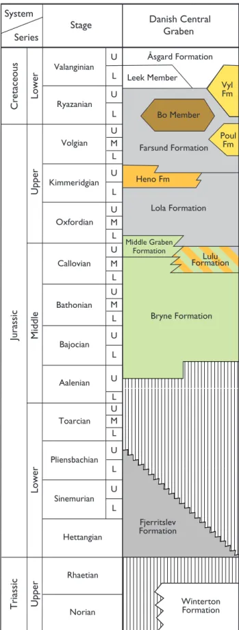
Middle Jurassic sandstones with interbedded mudstones and coals were encountered by the Lulu-1 well, the first exploration well in the Danish part of the Søgne Basin (Fig. 1). Similar deposits encountered in the Nor-wegian part of the Central Graben were included in the Bryne Formation, a formation erected by Vollset & Doré (1984). Jensen et al. (1986) extended the Bryne For-mation to the Middle Jurassic deposits of the northern part of the Danish Central Graben, although referring similar, coeval deposits of the southern part of the Fig. 2. Jurassic lithostratigraphy of the Danish Central Graben,
from Michelsen et al.(2003, this volume).
System
Series
Stage
Jurassic
Triassic
Åsgard Formation
Leek Member
Bo Member
Heno Fm
Lola Formation
Bryne Formation Danish Central
Graben
Ryazanian
Volgian
Kimmeridgian
Oxfordian
Callovian
Bathonian
Bajocian
Aalenian
Toarcian
Pliensbachian
Sinemurian
Hettangian
Rhaetian
Norian
Winterton Formation
Cretaceous
Valanginian
Fjerritslev Formation
Vyl Fm
Poul Fm Farsund Formation
Lower
U
p
p
e
r
Middle
Lower
Upper
U
L
U
L
L U
U M L
L M U
M L U
L U
U
L
L U M
L U
U
L U M L
Paralic and non-marine sandstones, siltstones, mudstones and coals Marine mudstones and siltstones
Unconformity
Offshore organic-rich marine shales
Submarine fan sandstones and siltstones
Shallow marine sandstones and siltstones
Hiatus
Middle Graben Formation
Danish Central Graben to the Central Graben Group of NAM & RGD (1980). In a re-evaluation of the litho-stratigraphy of the Danish Jurassic, the upper part of the Middle Jurassic succession in the northern part of the Danish Central Graben is referred to a new forma-tion, the Lulu Formation (Fig. 2; Michelsen et al. 2003, this volume). Most of the Middle Jurassic succession in the southern part of the Danish Central Graben previ-ously referred to the Central Graben Group is now included in the Bryne Formation, although the Middle Graben Formation, defined from the Dutch sector (see Herngreen et al. 2003, this volume), is retained in this area (Fig. 2; Michelsen et al. 2003, this volume). The boundary between the Bryne Formation and the Lulu For-mation is placed at the base of the first major coal or its correlative interval of thin coals and coaly mudstones in the upper part of the middle Jurassic succession.
In the Søgne Basin, the Middle Jurassic succession unconformably overlies Triassic and Permian deposits and is either succeeded conformably by marine mud-stones of the Upper Jurassic Lola Formation (Jensen et al.1986) or is overlain unconformably by Cretaceous deposits on structural highs. In the wells of the Søgne Basin, the thickness of the Middle Jurassic succession varies from 130 to 300 m; the succession may be absent from the top of structural highs, and it may attain a somewhat larger thickness in deeper parts of the basin. Based on detailed sedimentological analysis of cores, the Middle Jurassic of the Lulu-1 well was interpreted as deltaic interdistributary bay deposits overlain by coastal sediments (Frandsen 1986). Koch (1983) interpreted Middle Jurassic deposits further south in the Danish Central Graben as alluvial plain and delta plain deposits. Damtoft et al. (1992) suggested a fluvial channel and floodplain environment for the Bryne Formation, and Johannesen & Andsbjerg (1993) interpreted the Middle Jurassic succession in the Søgne Basin as an alluvial plain succession overlain by tidal and shallow marine deposits.
Biostratigraphy
Stratigraphically useful microfossils are rare in the stud-ied succession. The sparse biostratigraphic information available for this study comes from unpublished reports from the Geological Survey of Denmark and Greenland, reports from service companies, and the results of new investigations prepared for the sequence stratigraphic study by Andsbjerg & Dybkjær (2003, this volume). Only palynomorphs were used for dating in that study and the events are presented mainly as last occurrence
datum (LOD) of dinoflagellate cyst species. The events used and their relation to boreal standard zones are presented in Andsbjerg & Dybkjær (2003, this volume, fig. 3).
Age-specific microfossils have not been found in the lower part of the Bryne Formation in the study area. How-ever, the occurrence of the dinoflagellate cyst Scriniocassis
sp. at 3730 m in West Lulu-1 indicates an Aalenian or earliest Bajocian age. In the middle and upper parts of the Bryne Formation, the occurrence of the dinoflagel-late cysts Ctenidodinium combazii, Impletosphaeridium varispinosumand the LOD of the pollen Quadraeculina anelliformissuggest a broad Late Bajocian to Callovian age. More specifically, the occurrence of Ctenidodinium combazii at 3742 m in the middle part of the Bryne Formation in West Lulu-3 suggests an age not older than Late Bajocian for that interval. The occurrence of
Impletosphaeridium varispinosumin the incised valley deposits of the upper part of the Bryne Formation at 3602 m in West Lulu-1 and at 3705 m in West Lulu-3 indicates a latest Bathonian to early Callovian age. The LOD of the pollen Quadraeculina anelliformiseither immediately beneath or just above the base of the incised valley deposits in several wells (e.g. 3717 m in West Lulu-3, 4479 m in Lulita-1) supports a latest Bathonian age for valley incision and the initiation of valley infilling. The Lulu Formation, which constitutes the upper part of the Middle Jurassic succession, is poorly dated. However, the occurrence of Durotrigia filapicatain the uppermost Lulu Formation at 4430 m in Lulita-1 suggests an age not younger than the Late Callovian, and the LOD of the dinoflagellate cyst
Liesbergia scarburghensisin the lower part of the Lola Formation in several wells (Andsbjerg & Dybkjær 2003, this volume), indicates a Late Callovian – mid-Oxfordian age for the final transgression of the Søgne Basin. With ages spanning at least a period from the Early Bajocian to the latest Callovian, the Bryne and Lulu Formations represent about 18 Ma of deposition, according to the time-scale of Gradstein et al. (1994).
Sequence stratigraphic concepts and
nomenclature
Sequence stratigraphic principles and nomenclature in this study follow Posamentier et al.(1988, 1992), Posa-mentier & Vail (1988), Van Wagoner et al.(1988, 1990) and Hunt & Tucker (1992, 1995).
traced throughout the Danish Central Graben. The pre-sent study attempts a more detailed sequence strati-graphic subdivision based on key-surfaces and units that are traceable across the Søgne Basin. Andsbjerg & Dyb-kjær (2003, this volume) subdivided the Middle Jurassic
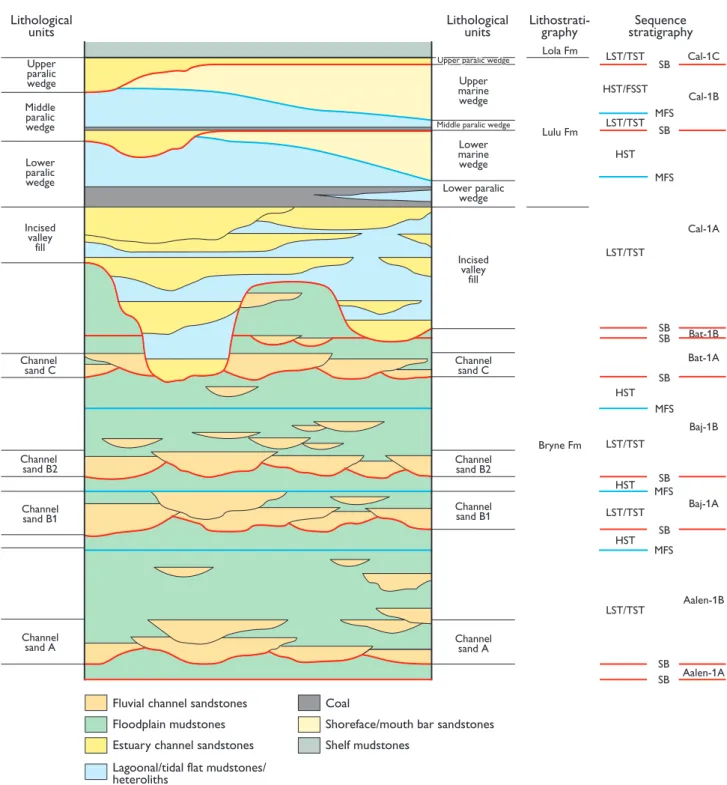
section into four sequences – the Aalen-1 (Aalenian), Baj-1, Bath-1, and Cal-1 sequences. In this higher res-olution local study, this nomenclature is retained but further subdivided (Fig. 3). Thus, Cal-1 of Andsbjerg & Dybkjær (2003, this volume) is divided into Cal-1A,
Upper paralic wedge
Lithological
units Lithologicalunits Lithostrati-graphy stratigraphySequence
Upper paralic wedge
Upper marine wedge
Lola Fm
Lulu Fm LST/TST LST/TST
HST/FSST
LST/TST
LST/TST LST/TST LST/TST HST
HST
HST
HST SB
MFS
MFS
MFS SB
SB SB
SB
SB
SB Bryne Fm
Lower marine wedge
Incised valley
fill
Channel sand C
Channel sand B2
Channel sand B1
Channel sand A
Middle paralic wedge
Lower paralic wedge Middle
paralic wedge
Lower paralic wedge
Incised valley
fill
Channel sand C
Channel sand B2
Channel sand B1
Channel sand A
MFS
MFS
SB Cal-1B Cal-1C
Cal-1A
Bat-1B Bat-1A
Baj-1B
Baj-1A
Aalen-1B
Aalen-1A SB
Fluvial channel sandstones
Floodplain mudstones
Estuary channel sandstones
Lagoonal/tidal flat mudstones/ heteroliths
Coal
Shoreface/mouth bar sandstones
Shelf mudstones
Cal-1B and Cal-1C. The sequences and their most impor-tant key surfaces are shown in Figures 3 and 4. The hier-archical nature of sequence stratigraphy, i.e. the potential subdivision of larger sequences into a number of smaller sequences, reflects the fact that sequences represent the varying time-spans over which different combina-tions of causal factors may operate. Influenced by a vari-ety of factors such as glacio-eustacy, tectono-eustacy, tectonics of various scales, and climate, sequences form over time scales ranging from tens of thousands of years to hundreds of millions of years (see discussion in Vail
et al.1977, Van Wagoner et al.1990, Miall 1997). Whereas the Middle Jurassic sequences outlined by Andsbjerg & Dybkjær (2003, this volume) represent time-spans of 5–10 Ma. which is consistent with the influence of intraplate stress (Cloetingh 1988; Hallam 1988; Miall 1997), the present study identifies sequences with dura-tions in the range 1–5 Ma., which may indicate a stronger influence of local tectonics.
Key surfaces and systems tracts
A systems tract is defined as a linkage of contempora-neous depositional systems defined by stratal geome-try at bounding surfaces, position within the sequence, and internal stacking patterns (Posamentier et al.1988). Sequences are subdivided into the lowstand systems tract (LST), the transgressive systems tract (TST), the high-stand systems tract (HST) and the falling stage systems tract (FSST; alternatively termed the forced regressive systems tract by Hunt & Tucker 1992, 1995). The low-stand systems tract (LST) consists of deposits formed at the lowest relative sea-level stand, bounded below by the mainly subaerial sequence-bounding unconformity (SB) and above by the first transgressive surface (TS). The TST consists of a succession of backstepping parase-quences; individual parasequences may exhibit a progra-dational pattern. The lower boundary of the TST is the first TS and the upper boundary is the maximum flood-ing surface (MFS). The HST is characterised by a progra-dational stacking pattern, which may be interrupted by subordinate transgressive events. The systems tract is bounded at the base by the MFS and at the top by the SB or by a regressive surface of marine erosion (RSME) if it is overlain by a falling stage systems tract (FSST). The FSST consists of the sediments deposited during falling sea level and is bounded by the RSME at the base and by the SB at the top.
There is a direct link between sequence development and relative sea-level change in the marine and marginal
marine realm. In upland settings, sea-level changes do not influence sequential development of deposition sig-nificantly. A more pronounced influence may be present in non-marine deposits of lowland settings, although it may be subordinate to other factors. The sporadic occur-rence of tidal indicators in the non-marine deposits of the Bryne Formation suggests that deposition took place on the lower part of a coastal plain where sea-level changes may have exerted a strong influence on sedi-mentation patterns and sequence development.
Data and methodology
Data from 9 released wells penetrating the Bryne Formation in the Søgne Basin were used in the present study (Fig. 1). A total of 875 m of core has been exam-ined and described. Graphic core logs were matched to gamma-ray (GR) and sonic logs, supplemented by density, neutron and resistivity logs, in order to gain an improved interpretation of the cored successions. The observed core-to-log relationships have been used in the interpretation of well logs from uncored intervals by extrapolating sedimentological interpretations of cores to the uncored sections. The well logs and sedi-mentological core logs formed the basis for the con-struction of cross-sections. Well-to-well correlations of key surfaces and characteristic units form a framework that guide correlations of other units and form the basis for the construction of palaeogeographic maps.
Sedimentary facies and depositional
environments
Approximately 875 m of slabbed cores were available for the description of sedimentary facies. Facies descrip-tions include the registration of lithology, grain size, pri-mary sedimentary structures and deformation structures including degree and type of bioturbation. A total of 30 facies are recognised (Table 1) and are grouped into nine facies associations (1–9), each of which represents a specific sedimentary environment.
Non-marine deposits
repre-Cal-1C
Cal-1B
Cal-1A Lola
Fm
Lulu Fm
Upper Bryne Fm
Lower Bryne Fm Bat-1B
Bat-1A
Baj-1B
Baj-1A
Aalen-1B
Aalen-1A Cal-1C
Cal-1B
Cal-1A
Bat-1A
Baj-1B
Baj-1A
Aalen-1B
Aalen-1A GR
GR
GR
GR
GR
GR
GR DT
DT DT
DT DT
DT
DT West Lulu-4
West Lulu-2
West Lulu-3
West Lulu-1 3/7-4
A B1
B2 C
Lulita-1 Amalie-1
Depositional environments Shelf mudstones
Paralic/shoreline sediments Coal
Incised valley fill
Floodplain/lacustrine sediments Fluvial channel sandstones
Pre-Jurassic strata
Key surfaces
Sequence boundary Normal fault
50 m
■ ■ ■ ■
■ ■
■ ■ ■ ■
■■ ■■ ■■ ■■
■
■
■
■
■■
■■
■
■
Amalie-1 3/7-4
Lulita-1
Lulu-1 West
Lulu 1
3
2 4
■
■
■■
■ ■
Søgne Basin
10 km
307
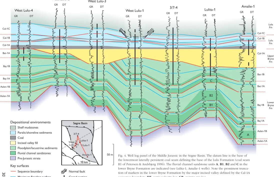
Fig. 4. Well log panel of the Middle Jurassic in the Søgne Basin. The datum line is the base of the lowermost laterally persistent coal seam defining the base of the Lulu Formation (coal seam
R1 of Petersen & Andsbjerg 1996). The fluvial channel sandstone units A, B1, B2and Cin the
Facies
Structureless and laminated siltstone and claystone
Interbedded siltstone and sandstone
Bioturbated siltstone and sandstone
HCS-dominated sandstone
SCS-dominated sandstone
Trough and planar cross-bedded sandstone
Horizontally laminated and planar cross-bedded sandstone
Conglomerate and pebbly sandstone
Poorly sorted, bioturbated muddy sandstone and heterolith
Horizontally laminated and current rippled sandstone
Structureless rooted sandstone
Fining-upwards cross-bedded sandstone with mud drapes
Fining-upwards interbedded mudstone and sandstone
Coarsening-upwards sandstone with abundant mud laminae
Coarsening-upwards cross-bedded sandstone with mud laminae
Fining-upwards heterolithic sandstone and mudstone 1
2
3
4
5
6
7
8
9
10
11
12
13
14
15
16
Description
Structureless or mm- to cm-scale interlaminated siltstone and claystone
Cm-scale interbedded siltstone and sandstone. Sharp-based, normal graded sand laminae show parallel lamination and wave ripples
Bioturbated siltstone, very fine-grained sandstone beds with sharp bases may show wave or combined flow ripples, parallel lamination and HCS
Very fine- and fine-grained sandstone with siltstone laminae. Sharp-based sandstone beds with HCS and subordinate wave ripple lamination
Fine-grained sandstone, SCS, low-angle planar cross-bedding and scour structures
Fine- to coarse-grained sandstone, occasionally pebbly. Trough cross-bedding, planar cross-bedding and subordinate current and wave ripples
Fine- to coarse-grained sandstone. Parallel lamination with low-angle erosion surfaces and low-angle planar cross-bedding
Clast-supported pebble and granule conglomerate, less common matrix-supported conglomerate and pebbly sandstone. Clast-supported conglomerate may show cross-bedding; conglomerate veneers on erosion surfaces
Poorly sorted sandstone with subordinate siltstone. Soft-sediment deformation structures and bioturbation dominate, some wave and current ripples may occur
Erosionally based fining-upwards units of very fine- to medium-grained sandstone. Parallel or gently inclined lamination, current ripples, local soft-sediment deformation structures or high-angle cross-bedding
Various sandstones and heteroliths fully or partly homogenised by roots
Fining-upwards units of fine- to coarse-grained sandstone. Planar and trough cross-bedding with ripple cross-laminated flaser and wavy cross-bedding in upper parts of units. Abundant clay laminae; clay clasts and coal debris, interbedded sandstone and mudstone may occur
Fine- and very fine-grained sandstone and heteroliths with mud clasts. Ripple cross-lamination, parallel cross-lamination, flaser, lenticular and wavy bedding, cross-bedding
Very fine- to fine-grained sandstone. Bioturbated with mud laminae and flasers, ripple cross-lamination
Very fine- to medium-grained sandstone and heteroliths. Cross-bedding, cross-lamination, flaser bedding, mud laminae
Thinly interbedded sandstone, mudstone and heteroliths. Ripple cross-lamination, parallel lamination, flaser bedding
Thickness Beds < 50 cm
Beds max. 10 cm
Silt beds less than 3 m, sand beds up to 10 cm, rarely to 50 cm
10–50 cm beds
20–50 cm beds
20–50 cm beds in units up to 3 m
5–15 cm beds in units up to 50 cm
Conglomerate beds max. 10 cm, pebbly sandstone beds up to 30 cm
5–10 cm beds in units up to 1 m
5–20 cm beds
50 cm – 3 m
4–10 m fining-upwards units
Fining-upwards units typically 50 cm – 2.5 m
Coarsening-upwards units up to 2 m
Coarsening-upwards units up to 4 m
Units less than 1 m
Biogenic structures
Weak to moderate bioturbation:
Anconichnus isp., Planolites isp. and
Teichichnus isp.
Moderate to intense bioturbation:
Teichichnus isp., Thalassinoides isp.,
Skolithos isp., Planolites isp.
Weak bioturbation
Trace fossils are rare
Bioturbation in the most fine-grained intervals: Diplocraterion isp. and Skolithos isp.
Trace fossils are rare: roots and (?)Skolithos isp.
Often thoroughly bioturbated:
Teichichnus isp., Diplocraterion isp.
Moderate bioturbation, roots may occur
Thoroughly homogenised by roots
Moderate, rarely intense bioturbation:
Teichichnus isp.
Moderate to intense bioturbation
Moderate to intense bioturbation:
Teichichnus isp.
Generally moderate bioturbation:
Teichichnus isp., Diplocraterion isp.
Moderate to intense bioturbation: common Diplocraterion isp., Planolites isp.
Interpretation
Offshore, fair-weather deposition and suspension fall-out after storms
Offshore, near storm wave base
Offshore – offshore transition, storm activity alternating with
long periods dominated by fair-weather conditions
Offshore transition, storm and waning storm deposition
Lower and middle shoreface, above fair-weather wave base
Upper shoreface. Rip channels, nearshore bars and troughs
Foreshore
Beach and breaker zone deposits. May represent a transgressive lag
Transgressive marine sandstone deposited below fair-weather wave base during rising sea level
Washover sediments
Beach ridge plain
Major tidal channel or active tidal inlet
Tidal creek or inactive major tidal channel
Tidal sand bar/flat
Proximal flood tidal delta or estuary sand bar
Facies
Coarsening-upwards/fining-upwards sandstone and heterolith
Structureless or laminated
mudstone and bioturbated sandstone
Organic-rich rooted mudstone
Coal
Fining-upwards interbedded sandstone and mudstone
Sandstone, fining-upwards or no grain-size trend
Intraformational conglomerate
Fining-upwards thin-bedded or cross-bedded sandstone
Chaotically bedded sandstone
Sideritic siltstone and mudstone
Coarsening-upwards units of deformed siltstone and sandstone
Coarsening-upwards units of sharp-based sandstone and siltstone
Disturbed silty mudstone
Organic-rich laminated mudstone 17
18
19
20
21
22
23
24
25
26
27
28
29
30
Description
Coarsening-upwards very fine- to medium-grained sandstone units. Planar cross-bedding, parallel lamination, current and wave ripple cross-lamination and small-scale HCS/SCS. Commonly associated with fining-upwards channel units
Parallel-laminated or structureless mudstone with interbeds and laminae of sandstone. Parallel lamination, wave ripples, flaser and lenticular bedding
Organic-rich mudstones with plant fragments, thin coals and with abundant rootlets
Sharp-based units, often fining-upwards, of cross-bedded and cross-laminated sandstone with abundant heterolithic beds and mud laminae. Abundant coal or mud clasts locally
Sharp-based fining-upwards cross-bedded and cross-laminated sandstone. Heterolithic sandstones may dominate upper part of units; some beds may have abundant coal and mud clasts. Thick amalgamated units may show no overall grain-size trend
Matrix- or clast-supported, pebble–cobble conglomerate, with sand matrix. Angular mud- or siltstone clasts. Conglomerate beds at base of fining-upwards sandstone units are parallel-stratified or cross-bedded
Sharp-based fining-upwards sandstones. Thin-bedded with current ripple cross-lamination, parallel lamination or cross-bedding. Intraformational clasts and coal fragments, soft-sediment deformation
Poorly sorted sandstone with deformed and overturned mud laminae. Coal and mud clasts scattered throughout
Siltstone and mudstone with siderite bands and nodules, abundant plant remains and roots. Indistinct patches of sandstone may occur
Stacked coarsening-upwards units of siltstone and sandstone. Dominated by soft-sediment deformation structures with current, wave, and climbing ripple lamination in sandstone units, parallel and climbing ripple lamination and wavy and lenticular bedding in siltstone units. Mudstone clasts and coal fragments locally abundant. Thinner, sharp based fining-upwards sandstones with deformed cross-bedding may occur at top of coarsening-upwards intervals
Coarsening-upwards units of very fine- to medium-grained sandstone with silt- and mudstone. Common parallel lamination, current ripple cross-lamination, root traces, soft-sediment deformation. Base gradational to floodplain mudstones
Mud- and siltstone, subordinate sandstone, coal debris. Parallel lamination, sediments disturbed by roots, soft-sediment deformation and pedogenesis
Organic-rich mudstones with sand and silt laminae
Thickness Units up to 5 m
Units less than 2 m
Less than 50 cm
Max. 5 m
Units max. 12 m
Units max. 8 m
Beds up to 75 cm
Units < 2 m
Beds typically 20–50 cm
Typically 0.5–2 m
2–5 m units. May be stacked in 10 m coarsening-upwards successions
Beds 10–50 cm, units up to 2 m
Typically < 1 m
Max. 8 m
Biogenic structures
Moderately bioturbated: Teichichnus isp.,
Diplocraterion isp.
Moderate to intense bioturbation by roots
Moderate to intense bioturbation by roots
Upper part of channel units may be bioturbated: Diplocraterion isp., Teichichnus isp.
Thoroughly bioturbated, mainly by roots
Interpretation
Bay-head delta/bay shoreface
Low energy outer estuary, estuary central basin or lagoon
Marsh or vegetated coastal swamp
Mire
Tidally influenced fluvial channel
Major fluvial channel
Channel lag deposits
Crevasse channel or minor fluvial channel
Channel margin deposits of fluvial channels
Abandoned channel fill
Lacustrine delta. Stacked minor coarsening-upwards units capped by channel sandstones may represent delta lobes of a larger lacustrine delta
Levee and crevasse spray
Floodplain fines
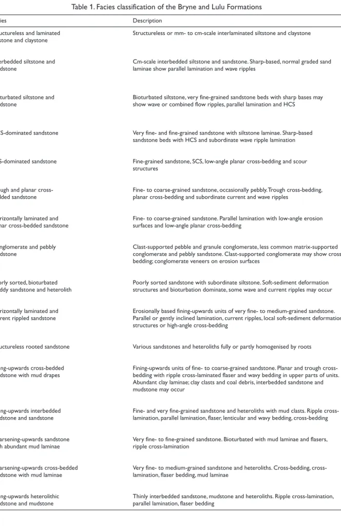
cm 0
10
20
30
40
50
60
70
80
90
A
West Lulu-3 3749.4 m
B
West Lulu-3 3751 m
C
West Lulu-3 3751.8 m
D
West Lulu-3 3753.3 m
E
West Lulu-3 3754.1 m
F
West Lulu-3 3756.4 m
SB
This page and facing page:
(arrowed) and palaeosol mottling. G–K: Selected intervals from the fluvial channel sandstone unit C (sequence Bat-1A) in West Lulu-2 (base lower right, top upper left; for location of core sections, see Fig. 14). The channel base defining the sequence boundary (SB, see core section K) is overlain by the active channel fill (facies association 1) comprising structureless and cross-bedded sandstones with abundant mudstone clasts and coal fragments (I–K, lower point bar) succeeded by sandstone and mudstone heteroliths, disturbed in places by bioturbation (rootlets arrowed) and soil-forming processes (G, H; upper point bar). The channel fill is capped by coal (G; facies association 4). L: Sandstone and heterolithic sandstones showing climbing ripple cross-lamination, representing a lacustrine or crevasse delta (facies association 2). West Lulu-1, sequence Bat-1B; for location of core section, see Fig. 15.
cm 0
10
20
30
40
50
60
70
80
90
G
West Lulu-23851.1 m
L
West Lulu-13626 m
H
West Lulu-2 3859.3 m
I
West Lulu-23860 m
J
West Lulu-23861.6 m
K
West Lulu-23862.2 m
senting fluvial channel fill, proximal floodplain, lake and distal floodplain, and vegetated floodplain.
Facies association 1: fluvial channel fill (facies 21–26)
Description. The fluvial channel fill association comprises erosionally based, up to 8 m thick, fining-upwards, chan-nel units. The chanchan-nel units are dominated by sandstone in the lower part and become heterolithic in the upper part (Fig. 5B–F). A conglomerate of mudstone clasts may occur immediately above the erosional base. The most common facies of the channel fill association are trough and planar bedded sandstone and ripple cross-laminated sandstone (Fig. 5B, D). The common chaoti-cally bedded sandstone facies is characterised by contorted bedding, soft sediment deformation and a chaotic tex-ture with abundant plant debris and intraformational mudstone clasts in places (Fig. 5E). In the upper part of the channel units, sandstone beds are interbedded with 10–30 cm thick heterolithic beds that may represent inclined heterolithic strata (Thomas et al.1987), a vari-ant of epsilon cross-stratification characteristic of tidally influenced fluvial channels (Smith 1987). Mudstone lam-inae, double mud drapes and flaser bedding, abundant in the sandstone facies of some units, particularly in the upper part of the Bryne Formation, suggest occasional tidal influence in the river system.
Interpretation. Fining-upwards channel units that can be correlated between most wells in the study area (Figs 3, 4), represent laterally extensive channel sand-stones deposited by laterally migrating, sinuous rivers. Chaotic bedding may be the result of bank collapse and/or post-depositional collapse of stems and other plant material deposited behind obstacles in the chan-nel. Similar deposits have been described by Alexander & Gawthorpe (1993; their facies S4) and by Guion et al.(1995) as part of their minor channel facies. The evi-dence of occasional tidal influence suggests deposition in a coastal plain environment.
Facies association 2: proximal floodplain
(facies 27–29)
Description. The proximal floodplain association con-sists of interbedded sandstone, siltstone and mudstone (Fig. 5L). The sandstones are generally less than 2 m thick, but may be amalgamated into units 4–5 m thick. The sandstone units may fine upwards, coarsen upwards
or show no overall grain-size trends. Primary structures include cross-bedding, current ripple lamination, climb-ing ripple lamination, wave ripple cross-lamination, parallel lamination and chaotic bedding with abundant mudstone and coal clasts. Soft sediment deformation structures are common. Siltstones and mudstones of this association are commonly structureless but may show deformation structures, parallel lamination and lenticular bedding.
Interpretation. The sandstones were deposited in small channels, as crevasse splays, on levees and as small lacustrine deltas. Sandstone units that show bi-directional current ripples, mud flasers and abundant mud lami-nae were probably influenced by tidal processes dur-ing deposition in fluvial channels or distributaries. Siltstones and mudstones are interpreted as waning flow deposits on levees and in small fluvial and crevasse channels or as the passive infill of abandoned channels.
Facies association 3: lake and distal floodplain
(facies 28–30)
Description. Mudstones and siltstones dominate the lake and distal floodplain association (Fig. 5K). Interbedded sandstones are not thicker than a few decimetres. Mudstones and siltstones form units up to 5 m thick; these are most commonly structureless or show paral-lel lamination. The paralparal-lel lamination is faint and may appear irregular and slightly deformed. Heterolithic units may show lenticular and wavy bedding and cur-rent and wave ripples in thin sand beds.
Interpretation. The sediments are interpreted as hav-ing been deposited in ponds, shallow lakes and on the distal levee, or represent the passive infill of abandoned channels.
Facies association 4: vegetated floodplain
(facies 20, 29, 30)
Description. Sediments with abundant root traces, mot-tled siltstones and mudstones and coal beds are com-bined in this facies association. Mottled siltstones and mudstones frequently have a light-coloured ‘leached’ appearance (Fig. 5G).
vegetation and soil-forming processes. Most soils formed under reducing conditions.
Marginal marine deposits
Back-barrier and estuarine deposits dominate the upper part of the Bryne Formation and, in the western part of the basin, the Lulu Formation. The marginal marine deposits are separated into five facies associations (5–9), representing estuary channels and bars, flood tidal deltas and washover fans, bay-head deltas and bay-fill, low-energy estuary and lagoon, and marsh and swamp.
Facies association 5: estuary channel and bar
(facies 12–15)
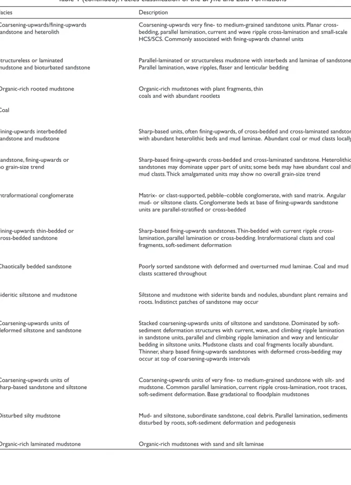
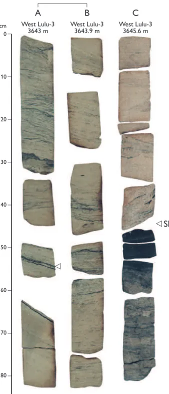
Description. The estuary channel and bar association is represented by 4–10 m thick sandstone-dominated units that may fine upwards, coarsen upwards or show no clear grain-size trend, and as 0.5–4 m thick, fining-upwards, fine- to very fine-grained sandstones and het-eroliths. The sandstones show planar and trough cross-bedding with common mudstone laminae (Fig. 6D), and ripple cross-lamination with abundant stone flasers (Figs 6C, E, 7). Coal fragments and mud-stone clasts occur in some beds, most commonly above erosional surfaces (Fig. 6K, L). Heterolithic strata, 5–20 cm thick, occur interbedded with the sandstones and may represent beds of inclined heterolithic stratification (Thomas et al. 1987). Interbedded sandstones, mud-stones and heteroliths in the fine-grained units show flaser, wavy and lenticular bedding and parallel lami-nation (Figs 6A, 8B, E). Up to 5 m thick coarsening-upwards units are formed by progressively thicker and coarser grained sandstone beds separated by thin mud-stone and siltmud-stone beds (Fig. 9). These sandmud-stone beds may show cross-bedding, ripple cross-lamination, and mudstone flasers and laminae, but may also be struc-tureless with the exception of a few inclined mudstone laminae and mudstone flasers. Intense bioturbation with abundant Teichichnusisp. is common (Fig. 9A, B).
Interpretation. The fining-upwards sandstone units, dominated by cross-bedding and ripple cross-lamina-tion with abundant mudstone laminae, double mud drapes and flaser bedding, are interpreted as estuary point bar deposits (Reineck & Wunderlich 1968; Visser 1980). Sandstone units that show similar sedimentary structures but lack overall grain-size trends are
inter-preted as amalgamated tidal channel sandstones. The finer-grained fining-upwards units represent the passive infill of major channels or the active fill of minor chan-nels. The coarsening-upwards sandstone units represent estuarine channel bars (Fenies & Tastet 1998) or mouth bar deposits of bay-head deltas.
Facies association 6: flood tidal delta and
washover fan (facies 14–16)
Description.The flood tidal delta and washover fan asso-ciation consists of up to 3 m thick, generally coarsen-ing-upwards units of sandstones and heteroliths, that may be overlain by fining-upwards units of well-sorted sandstone (Fig. 10F–H). In the coarsening-upwards units, fine-grained heterolithic beds show lenticular and wavy bedding. The most fine-grained sandstones are commonly strongly bioturbated, but some may show flaser bedding and parallel lamination. Coarser grained sandstone facies include trough cross-bedded, parallel-laminated and ripple cross-parallel-laminated sandstone. The coarser grained sandstones may have erosional sur-faces overlain by thin conglomerates. The fining-upwards units are dominated by well-sorted, or very fine-grained sandstone showing parallel lamination, low-angle planar cross-bedding, ripple cross-lamination and soft-sediment deformation structures.
Interpretation. The fine-grained heterolithic beds char-acterised by wavy and lenticular bedding and the coars-ening-upwards sandstones with abundant mudstone laminae and flaser bedding, frequently interbedded with lagoonal mudstones, are interpreted as the deposits of flood tidal deltas and tidal sand flats. The coarsen-ing-upwards trend and the association of physical struc-tures correspond well with descriptions of recent flood tidal deltas (e.g. Nichol & Boyd 1993). The interbed-ding with lagoonal sediments further supports this inter-pretation. The well-sorted, erosionally based, fining-upwards units that locally overlie flood tidal delta and tidal flat deposits show a close likeness to washover deposits described by Schwartz (1982).
Facies association 7: bay-head delta and bay-fill
(facies 4–7, 17, 18, 21)
cm 0
10
20
30
40
50
60
70
80
90
A
West Lulu-33667.3 m
B
West Lulu-33669.9 m
C
West Lulu-33670.8 m
D
West Lulu-33671.7 m
E
West Lulu-33674.2 m
F
West Lulu-33680.2 m
G
West Lulu-33684.6 m
H
West Lulu-33685.4 m
This page and facing page:
are dominated by current-generated structures, but wave-generated structures also occur. Sandstones with current-generated structures may occur as channel deposits in the upper part of coarsening-upwards suc-cessions. Minor units of well-sorted sandstone and het-erolith may show low-angle planar cross-bedding, swaley and hummocky cross-stratification, and wave ripple cross-lamination. Levels showing moderate bioturbation with Teichichnus isp. are evident in places. Deposits of this association frequently overlie fine-grained lagoonal deposits.
Interpretation. This association is interpreted to record the progradation of bay-head deltas into estuaries, lagoons, or bays. Depending on the amount of wave influence, the deposits were either slightly modified by small-scale wave activity, or reworked thoroughly by storm wave activity. Deposits may be difficult to dis-tinguish from coarsening-upwards estuary bar deposits of association 5.
Facies association 8: low-energy estuary and lagoon
(facies 14, 16, 18, 19)
Description. This facies association is represented by organic-rich mudstones, siltstones and heteroliths, show-ing parallel lamination, wavy and lenticular beddshow-ing, and ripple cross-lamination with mud-flasers, partly obliterated by biogenic activity (Figs 8D, E, 9I). Sed-imentary units of this association vary in thickness from a few decimetres to several metres.
Interpretation. The dominance of finer grain sizes sug-gests deposition in a low-energy environment. The assemblage of sedimentary structures is typical of a tidally influenced environment such as an estuary cen-tral basin or a lagoon with extensive tidal flats.
Facies association 9: marsh and swamp (facies 19, 20)
Description.Coals, mudstones and associated rooted het-eroliths are grouped in the marsh and swamp associa-tion. Mudstones and rooted heteroliths have a dark grey to black appearance, reflecting the high organic content (Fig. 9C, D). Both vitrinite-rich and inertinite-rich coals are present.
Interpretation. The vitrinite-rich coals represent depo-sition in a waterlogged, anoxic mire environment. The
cm 0
10
20
30
40
50
60
70
80
90
I
West Lulu-3 3689.5 m
J
West Lulu-33699.6 m
K
West Lulu-33702.2 m
L
West Lulu-33710.5 m
inertinite-rich coals represent a somewhat drier envi-ronment, with periodically oxic conditions in a swamp or raised bog. Pyrite in some coal beds suggests the occa-sional influx of marine water. The evidence of marine influxes and the association of the coals and rooted sediments with lagoonal deposits suggest that deposi-tion took place in back-barrier swamps and marshes (Petersen & Andsbjerg 1996).
Marine deposits
Marine deposits dominate the Lulu Formation in the cen-tral parts of the Søgne Basin, but thin units can be traced into the mainly paralic deposits in the western part of the basin. The marine deposits are separated into three facies associations: offshore, prograding shoreface and beach, and transgressive shelf and shoreface.
Facies association 10: offshore (facies 1, 2, 9)
Description.The offshore association consists of up to 50 cm thick units of structureless and laminated mud-stone, and cm-scale interbedded, heterolithic mudstone and sandstone. The association frequently forms coarsen-ing-upwards units with structureless mudstone in the basal part overlain by heterolithic mudstone with silt-stone and sandsilt-stone laminae and beds that show an upwards increase in thickness, grading into the more sandy deposits of the shoreface association (Figs 11A, F, 12I). Laminae may be normally graded, and show par-allel lamination and wave and combined flow ripple lam-ination. The sandstone beds are commonly sharp-based. The sandstone-dominated upper part of coarsening-upwards units may grade into hummocky cross-strati-fied deposits of the prograding shoreface and beach association. Bioturbation in the offshore association varies from weak to intense, but mudstones are com-monly completely bioturbated with few remaining phys-ical structures. Anconichnus isp.,Palaeophycus isp.,
Planolites isp. andTeichichnus isp. occur in the sand-stone beds.
Interpretation. Mudstones with rare laminae of siltstone or sandstone indicate that deposition took place below storm wave base. The thorough bioturbation of the mudstones suggests they were deposited on a shelf with oxic bottom conditions. A higher content of silt-stone and sandsilt-stone laminae suggests the occasional
cm 0
10
20
30
40
50
60
70
80
90
A
West Lulu-33643 m
B
West Lulu-33643.9 m
C
West Lulu-33645.6 m
SB
cm 0
10
20
30
40
50
60
70
80
90
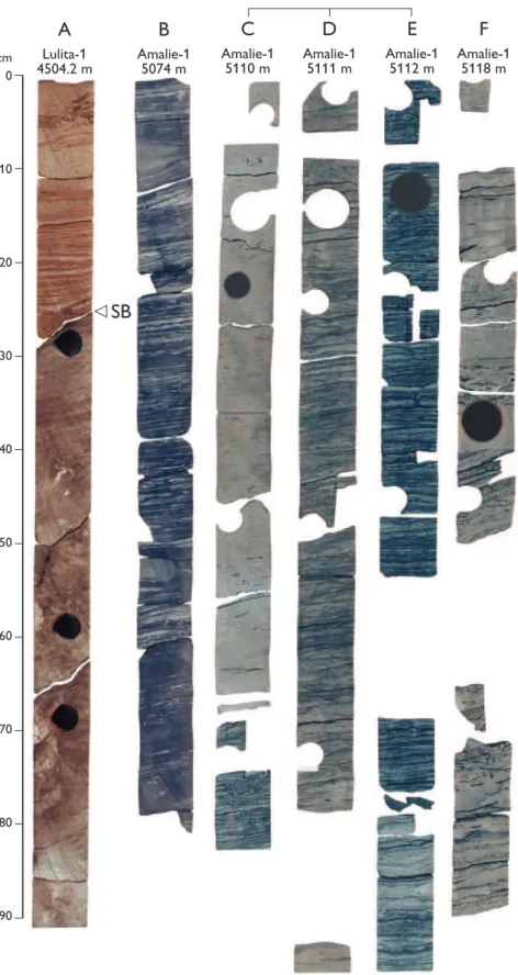
A
Lulita-1 4504.2 m
B
Amalie-1 5074 m
C
Amalie-1 5110 m
D
Amalie-1 5111 m
E
Amalie-1 5112 m
F
Amalie-1 5118 m
SB
Fig. 8. Core photographs of the incisedcm 0
10
20
30
40
50
60
70
80
90
A
West Lulu-3 3647.4 m
B
West Lulu-3 3648.2 m
C
West Lulu-3 3650.8 m
D
West Lulu-3 3651.7 m
E
West Lulu-3 3652.6 m
F
West Lulu-3 3653.5 m
G
West Lulu-3 3654.2 m
influence of oscillatory currents near storm wave base. Sharp-based sandstone laminae are interpreted as storm-sand deposits, and their finer-grained interbeds represent fair-weather sediments and sus-pension fall-out after storms. Deposition took place between storm wave base and fair-weather wave base.
Facies association 11: prograding shoreface and beach
(facies 3–8)
Description.The prograding shoreface and beach association is rep-resented by up to 12 m thick coarsening-upwards successions of sandstone and subordinate siltstone. The coarsening-upwards suc-cessions consist of very fine-grained, hummocky cross-stratified (HCS) and swaley cross-stratified (SCS) sandstones with siltstone interbeds in the lower part, overlain by low angle cross-bedded fine- to medium-grained sandstones and trough and planar cross-bedded fine- to coarse-grained sandstones (Figs 11B–E, 12). Parallel-laminated, low-angle cross-bedded and massive fine- to coarse-grained sandstones and pebble conglomerates may occur at the top of the successions. The HCS- and SCS-dominated sandstones occur as sharp-based, laminated beds ranging between a few decimetres and a few metres in thickness, separated by centimetres to decimetres thick siltstone beds. Lamination may be gently undulating, and typ-ically intersect and truncate at low angles. Individual hummocky cross-stratified units may grade into wave-rippled heterolithic siltstone and sandstone. SCS sandstones typically occur as thicker amalga-mated units that lack the heterolithic sub-units and the silty interbeds. The cross-bedded sandstones occur in poorly defined sets, usually a few decimetres thick.
Interpretation. The coarsening-upwards successions are interpreted as the deposits of prograding shelf, shoreface and shoreline systems. Minor, 2–4 m thick, coarsening-upwards units of typical shoreface deposits may represent wave-influenced mouth bars or ebb tidal deltas. The HCS-dominated units, commonly lowermost in the suc-cessions, were deposited by storm wave activity below fair-weather wave base in the offshore transition zone. The SCS deposits repre-sent more continuous wave activity on the lower shoreface, whereas the cross-bedded sandstones of the upper part of the succession rep-resent migrating dunes on the upper shoreface. The horizontally lam-inated and low-angle cross-bedded sandstones uppermost in the successions represent foreshore, beach and strandplain deposits.
Facies association 12: transgressive shelf and shoreface
(facies 9, 10)
Description.Deposits of the transgressive shelf and shoreface asso-ciation consist of poorly sorted, bioturbated muddy sandstones, sandy siltstones and mudstones and heteroliths, poorly sorted pebbly
cm 0
10
20
30
40
50
60
70
80
90
H
West Lulu-3 3655.7 m
I
cm 0
10
20
30
40
50
60
70
80
90
A
West Lulu-23781.6 m
B
West Lulu-23782.5 m
C
West Lulu-23790 m
D
West Lulu-23798.4 m
E
West Lulu-23799.2 m
cm 0
10
20
30
40
50
60
70
80
90
F
West Lulu-33617.4 m
G
West Lulu-33618.2 m
H
West Lulu-33619.1 m
I
West Lulu-33620 m
cm 0
10
20
30
40
50
60
70
80
90
A
Lulu-1 3594.5 mB
Lulita-1 4443.5 mC
Lulita-1 4444.4 mD
Lulita-1 4445.5 mE
Lulita-1 4446.3 mF
Lulita-1 4447.2 mG
Lulita-1 4448.4 mH
Lulita-1 4449 mTS
TS
sandstones, and conglomerates (Fig. 10A, F). The deposits are characterised by intense burrowing and a diverse ichnofauna (Fig. 11A).
Interpretation. These sediments were deposited in a shoreface or shallow shelf environment during a trans-gression. Physical structures reflecting the high energy level on the upper shoreface were partly or completely obliterated by burrowing organisms under more tran-quil conditions.
Architecture, depositional environments
and sequence stratigraphy
A regional unconformity subdivides the Bryne Formation into two separate parts described here as the lower and the upper Bryne Formation (Figs 3, 4); evidence sup-porting the recognition of this unconformity is pre-sented below. The architecture and depositional envir-onments of the lower and upper Bryne Formation and the Lulu Formation are described here, together with a sequence stratigraphic analysis of these units.
Lower Bryne Formation
Depositional architecture and environments
The lower Bryne Formation consists of floodplain deposits separated by several storeys of channel sand-stones. The four most distinct channel units are referred to as units A, B1, B2 and C (Figs 3, 4). These channel sandstones can be identified in most wells and proba-bly form laterally continuous sandstone sheets. The lowermost strata of the Bryne Formation are either fine-grained floodplain deposits located below the lower-most channel sandstone (unit A; West Lulu-1, West Lulu-4) or channel sandstone unit A resting directly and unconformably on Triassic or Permian deposits (West Lulu-2, West Lulu-3; Fig. 4).
In some wells, channel sandstone unit A is a 10–30 m thick multi-storey sandstone section of stacked, fining-upwards, 5–15 m thick sandstone units separated by mudstone beds, 1–2 m thick. In other wells, it is a sin-gle storey sandstone, 1–2 m thick (Fig. 4). The thick-ness variations may be related to pre-Middle Jurassic topographic relief. Cores are not available from this unit.
The two channel sandstone units B1 and B2 are closely associated, usually with the base of B2 lying c. 10 m above
the top of B1 (Fig. 4). In many wells, the gamma-ray logs of the combined unit B1–B2 show a characteristic fining-upwards – coarsening-upwards – fining-upwards pattern (e.g. Amalie-1, 5280–5260 m; West Lulu-4, 3768–3740 m; Fig. 4). Cores are available from unit B2 in the West Lulu-3 well (Figs 5, 13).
Channel sandstone unit C is a fining-upwards 10 m thick channel unit recognised in most wells and cored in West Lulu-1, West Lulu-2 and West Lulu-4 (Figs 5, 14). Unit C consists of cross-bedded sandstone with abun-dant wood fragments and mud clasts (Fig. 5H–K) and an increasing number of clay drapes up-section, some of which are paired. The upper part of the channel unit is heterolithic with decimetre thick sand/mud couplets in West Lulu-2 and abundant clay drapes and mud flasers in West Lulu-1.
The channel units show features that are character-istic of the deposits of sinuous channels. Most of the channel bodies have fining-upwards grain-size profiles above erosional bases, they appear to be laterally con-tinuous and regularly spaced mudstone laminae or beds may represent mud drapes on low-angle accretion sur-faces (Fig. 14). In addition to these features, the cores from sand sheets B2 and C show trough and planar cross-bedding, ripple cross-lamination and abundant defor-mation structures; the basal beds contain intrafordefor-mational mudstone clasts and wood fragments. The presence of double mud drapes, abundant flaser bedding and decimetre thick sand/mud couplets in channel unit C may indicate that the channel system was influenced by tidal processes. The channel sands were deposited in laterally migrating, sinuous river channels on a coastal plain. The evidence of tidal influence in unit C suggests it may have been connected downstream to an estu-ary. The upwards increase in tidal influence in this suc-cession may indicate an overall rise in relative sea level.
cm 0
10
20
30
40
50
60
70
80
90
A
West Lulu-13566.9 m
B
West Lulu-13567.7 m
C
West Lulu-13568.5 m
D
Lulu-1 3575.3 mE
Lulu-1 3576.2 mF
Lulita-1 4428.6 mG
Lulita-1 4431.9 mH
Lulita-1 4432.9 mI
Lulita-1 4433.8 mJ
Lulita-1 4434.7 mTSME
Fig. 12. Core photographs of marine shelf and shoreface deposits (facies associations 10–12) from the upper marine wedge of the Lulu Formation (Cal-1B sequence).
A–C: Sandstones and heteroliths from wave-influenced mouth bar or protected shoreface deposits in West Lulu-1 (base lower right, top upper left; for location of core sections, see Fig. 18). Note the pebble lag (facies association 12) at the transgressive surface of marine erosion (TSME), and the maximum flooding surface (MFS), c. 10 cm higher in the section.
D, E: Wave-dominated shoreface deposits (facies association 11) in the Lulu-1 well showing coarsening-upwards sandstones dominated by SCS (base lower right, top upper left; for location of core sections, see Fig. 19).
Sedimentary/biogenic structures
Erosional surface
Parallel bedding/lamination
Planar cross-bedding
Trough cross-bedding
Low-angle cross-bedding
Hummocky cross-stratification
Cross-lamination and climbing ripples
Bimodal current-ripple lamination
Wave ripples
Flaser bedding
Wavy bedding
Lenticular and silt-streaked bedding
Mudstone/coal chips
Disturbed bedding
Load structures
Water escape structures
Synaeresis cracks
Bioturbation
Rootlets
5 m
■ ■ ■ ■
■ ■ ■ ■ ■ ■
■■ ■■ ■■
■■
■
■
■■
■■
■■
■
■
Amalie-1 3/7-4
Lulita-1
Lulu-1 West
Lulu 1
3
2 4 West Lulu-3
GR
fluvial channel
floodplain distal floodplain
and lake
Channel sand B2
Baj-1B SB Baj-1B MFS Cal-1A SB
3711 m
3730
3758
5A 5B 5C 5D 5E
5F
■
■
■■
■ ■
Si
Clay Sand Gr
Lithology Coal
Claystone
Siltstone
Sandstone
Depositional environments Floodplain
Fluvial channels
Key surfaces
Sequence boundary (SB)
Maximum flooding surface (MFS) Søgne Basin
10 km
Fig. 13. Sedimentological core log and gamma-ray (GR) log of sequence Baj-1B in West Lulu-3. The channel sand B2 is located above the Baj-1B SB in the basal part of the illustrated section. The Baj-1B MFS is placed in the middle of the thick
lamination and slump structures, as well as dispersed rip-up mud clasts, root traces and pedogenic mottling (Fig. 5). The deposits are interpreted as levees, consisting of proximal crevasse splays, small channel fills and small deltas, and more distally as lake, swamp and dis-tal crevasse splay deposits; these sediments are referred to the proximal floodplain association, the lake and distal floodplain association and the vegetated flood-plain association. Palynological evidence for marine conditions is scarce in these deposits in the Søgne Basin, although rare marine palynomorphs have been found in the succession separating units B2 and C in West Lulu-3 indicating that short-lived marine incursions may have occurred.
The succession between channel unit C and the Cal-1A SB includes both channel sandstones and flood-plain deposits (Fig. 4). The succession attains a thick-ness of 30 m in Lulita-1, 50 m in West Lulu-1, 60 m in Amalie-1 and 65 m in 3/7-4. Channel sandstones dom-inate the succession in the West Lulu-1 and 3/7-4 wells. Cross-bedding is less prominent in the channel sand-stones of this succession than in units B2 and C. Mudstone clasts and soft-sediment deformation are com-mon, and current ripple and climbing ripple lamination occur in the upper part of channel units (Fig. 5). Root horizons and pedogenic mottling are abundant in the more fine-grained deposits. Fine-grained sediments dominate the succession in the wells closest to the basin axis. In Lulita-1, a 14 m thick section of coals and organic-rich mudstones overlie the channel sandstones at the base of the succession (Fig. 15). Most distinctive among the fine-grained deposits is a 50 m succession of mudstones with thin sandstone and siltstone interbeds in Amalie-1. Due to the lack of dinoflagellate cysts from this unit, it is interpreted to represent a lacustrine envi-ronment. Sandy and silty interbeds represent lacustrine delta and lacustrine delta plain/distal floodplain deposits. The 14 m thick coal-bearing section in Lulita-1 repre-sents a swamp environment.
A relatively deep lake existed in the southern and central part of the basin simultaneously with an active floodplain along the western margin. At least some of the channel sandstones in West Lulu-1 and 3/7-4 may represent distributaries of lacustrine deltas (Fig. 15). Although there is no palynological evidence for marine conditions, short-lived marine incursions of the coastal plain may occasionally have turned the lake into a brackish water lagoon or bay.
Sequence stratigraphy
Key surfacesThe basinwide extent of both the erosional bases of major channel sandstones and the mudstones that are located at the turnaround points of the fining-upwards – coarsening-upwards successions between the sand-stones, suggests that they are not simply the result of autocyclic facies shifts but more likely resulted from regional base-level changes. Both channel base diastems and turnaround points can thus be seen as sequence stratigraphic key surfaces.
Sequence boundaries in the lower Bryne Formation are defined by channel base diastems of the major, lat-erally extensive channel sandstones (Fig. 4). Although key surfaces such as the maximum flooding surface (MFS) and the transgressive surface (TS) do not extend landwards beyond the bay-line (Posamentier & Vail 1988), non-marine equivalents to the MFS are assumed to occur within widespread lacustrine and floodplain deposits. The presence of an equivalent to the MFS in this setting results from the influence of relative sea-level fluctuations on the groundwater level in the lower coastal plain. Surfaces that separate units of amalgamated, laterally extensive channel sandstones from significantly more fine-grained floodplain successions may represent a land-wards expression of marine flooding events. In addi-tion, growth of coal-forming peat due to a rise in the groundwater table and associated generation of new accommodation, may be the landwards expression of a marine flooding surface (Petersen & Andsbjerg 1996).
Systems tracts
In the lower Bryne Formation, the fluvial sand sheets fine upwards or occur as amalgamated sandstones with-out a visible grain-size trend (e.g. Baj-1A in 3/7-4). The laterally continuous fluvial sand sheets typically found above the sequence boundaries in the alluvial plain deposits represent the LST and the lower part of the TST (Figs 3, 4). They are comparable to the low accom-modation systems tract of Dreyer et al.(1995), and the amalgamated fluvial sand sheet of Shanley & McCabe (1991, 1993, 1994) and Olsen et al.(1995).
5 m
West Lulu-1 GR
West Lulu-2 GR
West Lulu-4
2.5 km
1.8 km
GR
3668 m
3681
3848
5G
5H 5I 5J 5K m
3862
3874 3692
3699
3698 3685 3667 3649 m
fluvial channel sheet vegetated floodplain
vegetated floodplain
Bat-1B SB
Bat-1A SB Bat-1A MFS
Channel sand C Cal-1A SB
Coal
Claystone
Siltstone
Sandstone
Floodplain
Fluvial channels
Sequence boundary (SB)
Maximum flooding surface (MFS)
Lithology Depositional environments Key surfaces
Si
Clay Sand Gr
Si
Clay Sand Gr
Si
Clay Sand Gr
■ ■ ■ ■ ■ ■ ■ ■ ■ ■
■■ ■■ ■■
■■
■
■
■■
■■
■■
■
■
Amalie-1 3/7-4
Lulita-1
Lulu-1 West
Lulu 1
3
2 4
■
■
■■
■ ■
Søgne Basin
10 km
Fig. 14. Log panel (GR and core logs) of sequences Bat-1A and Bat-1B in West Lulu-4, West Lulu-2 and West Lulu-1. The channel sandstone unit C which represents a laterally extensive fluvial channel sand is located above Bat-1A SB at the base of the section; the Bat-1A MFS represents abandonment of the channel system. The sec-tion is deeply incised by the Cal-1A SB, interpreted as the base of an incised valley. The posisec-tions of cores illustrated with photographs here are indicated on the
sed-imentological logs (e.g. 5Kindicates core photograph in Fig. 5K). Depths of important surfaces, facies changes or core breaks are indicated (in metres below reference
level). For full legend, see Fig. 13; inset map shows the location of the transect running SW–NE.
periods of lowstand and early base-level rise may have effectively prevented floodplain aggradation (Wright & Marriott 1993).
The overbank-dominated deposits between the top of the channel sandstone sheets and the MFS, consti-tuting the upper part of the TST, are organised into a fining-upwards succession with a gradually decreasing sand/shale ratio. Mudstones of mainly lacustrine origin become increasingly common upwards. Soil profiles and root horizons are common (Fig. 5G, H, L).
The overall fining-upwards trend and accompanying decreasing sandstone/mudstone ratio are interpreted to reflect a sea-level rise that caused a rising watertable and wetter conditions on the coastal plain. The increas-ing rate of creation of accommodation durincreas-ing risincreas-ing base level favoured high levels of storage of floodplain sediments and more isolated channel bodies (Shanley & McCabe 1993; Wright & Marriott 1993). The transgres-sive floodplain deposits are equivalent to the heterolithic unit with isolated fluvial sandbodies of Olsen et al.
(1995) and the lower part of the high accommodation systems tract of Dreyer et al.(1995).
The floodplain highstand deposits are separated from the floodplain transgressive deposits by a MFS. The MFS is picked in a mudstone bed that is typically organic-rich and can be correlated through most or all the wells in the study area. The highstand floodplain deposits are a coarsening-upwards succession that shows an increase upwards in sandstone/mudstone ratio and sand bed thickness. The lacustrine and distal floodplain mud-stones are interbedded with siltmud-stones and sandmud-stones that were deposited as levee deposits, crevasse splays and crevasse deltas. Channel sandstones are less com-mon than in the transgressive floodplain deposits. The coarsening-upwards succession of proximal floodplain deposits developed as a result of decreasing rates of base-level rise and accommodation space generation.
Similar successions in non-marine settings have been referred to the highstand systems tract by Shanley & McCabe (1991, 1993), as highstand depositional sys-tems by Wright & Marriott (1993) and as the uppermost heterolithic interval by Olsen et al. (1995).
Sequences of the lower Bryne Formation
The Bryne Formation consists of seven sequences of alluvial plain or fluvially-dominated coastal plain deposits. The Aalen-1, Baj-1 and Bat-1 regional se-quences of Andsbjerg & Dybkjær (2003, this volume) are subdivided here into the Aalen-1A, Aalen-1B, Baj-1A, Baj-1B, Bat-1A and Bat-1B sequences. The uppermost
part of the Bryne Formation is included in the Cal-1A sequence (see below) that also includes sediments referred to the Lulu Formation (Fig. 4).
Aalen-1A sequence. The deposits located between the base Middle Jurassic unconformity and the first intra-Middle Jurassic sequence boundary (SB Aalen-1B) are referred to the Aalen-1A sequence. Due to onlap of the pre-Middle Jurassic subcrop the Aalen-1A sequence is only seen in wells that penetrate the deepest parts of the Middle Jurassic.
Aalen-1B sequence.Channel sandstone unit A is referred to the LST/TST of sequence Aalen-1B. Most of the flood-plain deposits separating channel sandstone units A and B1 form the HST of Aalen-1B.
Baj-1A sequence.Channel unit B1 and the coarsening-upwards unit of floodplain deposits between B1 and B2 form sequence Baj-1A.
Baj-1B sequence. This sequence is made up of chan-nel sandstone unit B2 and the fining-upwards – coarsen-ing-upwards succession of floodplain deposits separating unit B2 from unit C.
Bat-1A sequence.In most wells, channel sandstone unit C forms the LST/TST of sequence Bat-1A. The HST is a unit of coarsening-upwards floodplain deposits.
Bat-1B sequence. The Bat-1B sequence is not present in the westernmost wells where it has been removed by erosion at the Cal-1A SB. Where present, it consists of channel sandstones above the SB and a fining-upwards – coarsening-fining-upwards succession of flood-plain and lacustrine deposits (Fig. 15).