© School of Engineering, Taylor’s University
THE INFLUENCE OF WAVE PATTERNS AND FREQUENCY
ON THERMO-ACOUSTIC COOLING EFFECT
YOUSIF A. ABAKR1, MUSHTAK AL-ATABI2,*, CHEN BAIMAN1
1
Department of Mechanical, Materials and Manufacturing Engineering, The University of Nottingham Malaysia Campus, Semenyih, Selangor, Malaysia
2
School of Engineering, Taylor’s University, Taylor's Lakeside Campus, No. 1 Jalan Taylor's, 47500, Subang Jaya, Selangor DE, Malaysia
*Corresponding Author: [email protected]
Abstract
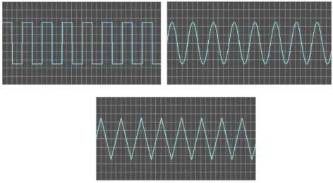
With the increasing environmental challenges, the search for an environmentally benign cooling technology that has simple and robust architecture continues. Thermo-acoustic refrigeration seems to be a promising candidate to fulfil these requirements. In this study, a simple thermo-acoustic refrigeration system was fabricated and tested. The thermo-acoustic refrigerator consists of acoustic driver (loudspeaker), resonator, stack, vacuum system and testing system. The effect of wave patterns and frequency on thermo-acoustic cooling effect was studied. It was found that a square wave pattern would yield superior cooling effects compared to other wave patterns tested.
Keywords: Thermo-acoustic, Refrigeration, Frequency, Wave, Vacuum.
1. Introduction
There is a growing need for heat removal from an increasing thermal source density that is a result of the creation of comfortable living environment and the advancements in manufacturing of fast, efficient and miniaturised electronic devices. However, in an age of impending energy and environmental crises, current cooling technologies continue to generate greenhouse gases with high energy costs [1].
centuries by glassblowers who occasionally reported hearing their heated vessels emitting pure tones [2]. The recognition that the thermo-acoustic heat pumping cycle was intrinsically irreversible made this discovery even more significant. Traditional heat engine cycles, such as the Carnot Cycle typically studied in elementary thermodynamics courses, assume that the individual steps in the cycle are reversible. In thermo-acoustic engines, the irreversibility due to the imperfect (diffusive) thermal contact between the acoustically oscillating working fluid and a stationary second thermodynamic medium (the "stack") provides the required phasing. This "natural phasing" has produced heat engines which require no moving parts other than the self maintained oscillations of the working fluid [3].
The recent growing interest in this technology is attributed to its simple yet robust architecture and its use of environmentally safe gases. The use of inert gases as the thermodynamic working fluid in thermo-acoustic refrigerators provides a potentially attractive alternative to the conventional refrigeration technology that employs man-made chemicals.
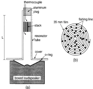
In 1979, Ceperley proposed a pistonless Stirling engine without any moving parts [4] using the propagation of acoustical waves through a differentially heated regenerator which resulted in gas in the regenerator undergoing a Stirling thermodynamic cycle. Yazaki et al. [5] demonstrated a prototype acoustic cooler that uses Stirling cycles executed by a traveling wave with high acoustic impedance thermoacoustically induced in a looped tube. The tube has no moving parts, only a pair of stacks sandwiched between two heat exchangers: one amplifies the acoustic power and the amplified wave supplies the driving energy to pump heat directly within the second stack. Russell and Weibull [6] built a low cost tabletop thermo-acoustic refrigerator for demonstration purposes. This thermo-acoustic refrigerator was built from a boxed loudspeaker, acrylic tubing and sheet, a roll of 35 mm film, fishing line, an aluminium plug, and two thermocouples. Temperature differences of more than 15°C were achieved after running the cooler for several minutes. Thermo-acoustic cooling units have been demonstrated aboard the Space Shuttle in 1992 and aboard the USS Deyo (DD 989) in 1995 to cool radar electronics [7].
This paper is aimed at exploring the basic principles of thermo-acoustic refrigeration with special attention to the influence of wave patterns and frequency on the effectiveness of the thermo-acoustic cooling effect.
2. Experimental Setup and Procedure
The thermo-acoustic refrigerator used in this study is based on the design proposed by Russell and Weibull [6] and shown schematically in Fig. 1.
closely spaced surfaces aligned parallel to the length of the resonator tube. The stack was made from a 35 mm photographic film role separated by fishing line to allow the air to move along the longitudinal axis of the acrylic tube.
Fig. 1. (a) Schematic Diagram of the Thermo-acoustic Refrigerator, (b) Cross Section of the Stack Showing How the Film Layers were Separated
by Fishing Line [6].
(a) (b)
Fig. 2. (a) Experimental Setup, (b) The Stack.
3. Results and Discussion
Figure 3 shows the maximum temperature differences between the two ends of the stack resulted from the use of different wave patterns, covering a range of frequencies ranging from 365 Hz to 425 Hz.
Fig. 3. Maximum Temperature Differences vs. Frequencies for Different Wave Patterns.
4. Conclusion
A simple thermo-acoustic refrigeration apparatus was constructed and tested using different wave patterns. A maximum temperature difference of 28oC was achieved using square wave at frequency of 405 Hz. The thermo-acoustic refrigeration seems to be a promising technology worth further investigation.
References
1. Newman, J.; Cariste, B.; Queiruga, A.; Davis, I.; Plotnick, B.; Gordon, M.; and San Martín, S. (2006). Thermoacoustic refrigeration. GSET Research Journal, 1-9.
2. Rayliegh, J.W.S.; and Lindsay, R.B. (1945).The theory of sound. (2ndEd.), Volume Two, Dover Publication.
3. Garrett, S.L.; Hofler, T.J.; and Perkins, D.K. (1993). Thermoacoustic refrigeration. Alternative Fluorocarbons Environmental Acceptability Study, Refrigeration and Air Conditioning Technology Workshop Breckenridge Hilton, Breckenridge, CO.
4. Ceperley, P.H. (1979). A pistonless Stirling engine -The traveling wave heat engine.The Journal of the Acoustical Society of America, 66(5), 1508-1513. 5. Yazaki, T.; Biwa, T.; and Tominaga, A. (2002). A pistonless Stirling cooler.
Applied Physics Letter, 80(1), 157-164.
6. Russell, D.A.; and Weibull, P. (2002). Tabletop thermoacoustic refrigerator for demonstrations. American Journal of Physics, 70(12), 1231-1233. 7. Johnson, R.A.; Garrett, S.L.; and Keolian, R.M. (2009). Thermoacoustic