American Journal of Applied Sciences 5 (1): 7-17, 2007 ISSN 1546-9239
© 2007 Science Publications
Corresponding Author: Stojan Kravanja, University of Maribor, Faculty of Civil Engineering, Smetanova 17, Postal Code: SI-2000, Maribor, Slovenia, Tel: + 386 2 22 94 300, Fax: + 386 2 25 24 179
7
Cost Optimization of Composite I Beam Floor System
Uroš Klanšek and Stojan Kravanja
Faculty of Civil Engineering, University of Maribor, Smetanova 17,
2000-SI Maribor, Slovenia
Abstract: The paper presents the cost optimization of the composite I beam floor system. The
composite I beam floor system is designed to be constructed up of a reinforced concrete slab and doubly-symmetrical welded steel I beams. The optimization was performed by the nonlinear programming approach, NLP. An accurate objective function of the manufacturing material, power and labour costs was developed and applied for the optimization. The composite I beam floor system was optimized according to Eurocode 4 for the conditions of both the ultimate and the serviceability limit states. A numerical example of the cost optimization of a composite I beam floor system is presented at the end of the paper to expose the advantages of the proposed approach.
Keywords: Structural optimization, nonlinear programming, composite structures, welded
structures, manufacturing costs
INTRODUCTION
Cost effective design of building structures is commonly obtained after the time-consuming trial-and-error analysis of various structural alternatives. In the conceptual design level, the costs related with a change in the structural design are in most cases low. The possibilities of such a change to decrease (or increase) the costs in the construction level are numerous. Since the state-of-the-art optimization methods in comparison with traditionally used trial-and-error methods generate more effective structural design, a significant construction cost savings may be obtained on account of an accurate cost optimization at the conceptual design level.
Over the last three decades, the cost optimization of composite structures was mainly considered from the viewpoint of the development and application of different optimization techniques[1–4]. Most of the published research works include simplified cost objective functions with fixed cost parameters. In this sense, the cost optimization of cable-stayed bridges with composite superstructures was presented by Long et al.[5]. The defined cost objective function includes concrete, structural steel, reinforcement, cable stays and formworks costs. The optimization of composite floors, presented by Adeli and Kim[6], was carried out by an employment the cost objective function, which
contained the costs of concrete, steel beams and shear studs. The optimization based comparison between composite I beams and composite trusses, introduced by Kravanja and Šilih[7], was accomplished by using the fixed cost parameter based objective functions, which comprised the costs of concrete, structural steel, reinforcement, shear studs, anti-corrosion paint, fire protection paint F 30, sheet-steel cutting costs, welding costs and the costs of the formworks.
This paper presents the cost optimization of the composite I beam floor system, consisted of a reinforced concrete slab and doubly-symmetrical welded steel I beams. The structural optimization was performed by the nonlinear programming (NLP) approach taking into account design constraints defined according to Eurocodes[8–11]. A detailed objective function of the structure’s manufacturing costs was developed and applied. The proposed objective function includes the material, power consumption and labour cost items, required to handle all the necessary manufacturing costs of the composite I beam floor system. Moreover, it also enables the engineer a complete and detailed insight into the manufacturing cost distribution of the obtained optimal structural design. It should be noted that the engineering, amortisation, transportation, erection, overhead, and maintenance costs, the costs of scrap as well as other expenses are not considered in the scope of this paper.
Author Manuscrip
A numerical example of the cost optimization of a composite I beam floor system with the span of 30 m is presented at the end of the paper to expose the advantages of the proposed approach.
MATERIALS AND METHODS
Composite I beam floor system: The composite I
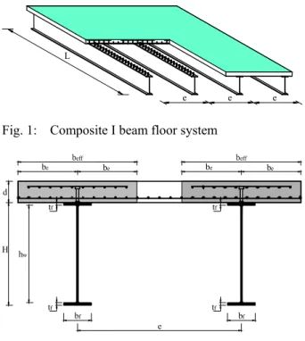
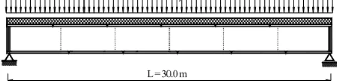
beam floor system is designed to be built up of the reinforced concrete slab of constant depth and doubly-symmetrical welded steel I beams, see Fig. 1. The full composite action between the concrete and the steel parts of the cross-section is achieved by the cylindrical shear studs, welded to the top of steel section and embedded in concrete, see Fig. 2. Both flanges and the web of the steel I section are connected together by the fillet welds.
The composite I beam floor system was designed according to Eurocode 4[11] for the conditions of both the ultimate and the serviceability limit states. The design loads were defined considering the requirements of Eurocode 1[8]. The concrete slab was designed as the continuous spanning slab, running over the steel I beams, with respect to Eurocode 2[9]. The design of structural steel members was performed upon the Eurocode 3[10] specifications.
e L
e e
Fig. 1: Composite I beam floor system
hw d
H
be be
eff be
eff be
e bf
tf
tf tf
bf tf
Fig. 2: Vertical cross-section of the composite I beam floor system
The following ultimate limit state conditions were checked: plastic resistance to the bending moment of the effective composite cross-section; plastic shear resistance and shear buckling resistance of the steel section; plastic bearing/shear resistance of the cylindrical shear studs; resistance of fillet welds; plastic resistance to the bending moment of the concrete slab; and resistance to the longitudinal shear of the concrete slab.
Considering the serviceability limit state conditions, the composite I beam floor system was checked for vertical deflections. The vertical deflections were calculated by using the elastic method, considering the effective second moment of the cross-section area and the effects of the creep/shrinkage of concrete. Both, the total deflection δmax subjected to the overall load and the deflection δ2subjected to the variable imposed load were calculated to be under the limited maximum values: L/250 and L/300, respectively.
NLP optimization: The optimization of the composite I beam floor system is proposed to be performed by the nonlinear programming approach, NLP. A general non-linear continuous optimization problem can be formulated as an NLP problem in the form:
Min z = f(x) subjected to:
h(x) = 0 (NLP) g(x) ≤ 0
x ∈ X = { x x ∈ Rn, xLO ≤ x ≤ xUP }
where x is a vector of the continuous variables, defined within the compact set X. Functions f(x), h(x) andg(x) are the (non)linear functions involved in the objective function z, the equality and inequality constraints, respectively. All the functions f(x), h(x) andg(x) must be continuous and differentiable.
As regards the optimization of composite I beam floor system, the vector of continuous variables defines dimensions, cross-section characteristics, forces, stresses, strains, cost parameters, etc. The system of equality and inequality constraints as well as the bounds on variables determines a design, load, stress, resistance and deflection conditions taken from the structural analysis. In this paper, a cost objective function is proposed to minimize the structure’s manufacturing costs.
The defined cost objective function is proposed to be subjected to structural analysis constraints, checking for both the ultimate and the serviceability limit states according to Eurocodes. The task of the optimization is
Author Manuscrip
9 to find the optimal structural design and the optimal concrete/steel materials considering the defined criterion of the optimization, namely the minimum of the manufacturing costs.
With reference to the given NLP optimization problem formulation, the optimization model COMBOPT (COMposite Beam OPTimization) was developed for the optimization of the composite I beam floor system. A high level language GAMS (General Algebraic Modelling System)[12] was used for the mathematical modelling and for data inputs/outputs.
Cost objective function: The optimal design of
composite I beam floor system is proposed to be determined by the minimum of the manufacturing costs. Here, the manufacturing costs are defined as a multitude of the material costs, power consumption costs and labour costs, required for the fabrication of the composite I beam floor system. The fabrication times, the electrical power consumption and the material consumption are also included in the objective function, which provides the engineer a complete insight into the distribution of the manufacturing costs. The proposed objective function of the manufacturing costs is defined in the following form:
min: Cost = {CM,s,c,r + CM,sc + CM,e + CM,ac,fp,tc + CM,f + CM,c,gas + CM,c,oxy + CP,gm +
CP,w + CP,sw + CP,v + CL,c,oxy-gas + CL,g + CL,p,a,t + CL,SMAW + CL,sw + CL,spp + CL,f + CL,r + CL,c + CL,v +
CL,cc} / (e · L) (1)
where the variable Cost (€/m2) represents the manufacturing costs per m2 of the useable surface of the composite floor system; the denotations CM,..., CP,... and CL,... represent the considered material, power and labour cost items calculated in €; e (m) is the intermediate distance between the steel I beams and L (m) is the span of the composite floor system. The considered material, power and labour costs are introduced in the following equations where detailed description and values of all used parameters may be found in paper by Klanšek and Kravanja[13].
The material costs of the structural steel, the concrete and the reinforcement:
r s r M c c M s s s M r c s
M c V c V c V
C ,,, = , ⋅ρ ⋅ + , ⋅ + , ⋅ρ ⋅ (2)
where cM,s (€/kg), cM,c (€/m3) and cM,r (€/kg) represent the prices of the structural steel, the concrete and the
reinforcement, respectively; ρs denotes steel density 7850 kg/m3; Vs (m3), Vc (m3) and Vr (m3) are the volumes of the structural steel, the concrete and the reinforcement materials, respectively.
The material costs of the shear studs:
sc sc M sc
M c n
C , = , ⋅ (3)
where cM,sc (€/stud) and nsc are the price and the number of studs, respectively.
The electrode material costs[14]:
w s w e M e M l EMY A c
C = ⋅ ×10-6⋅ ⋅ 1 ⋅
,
, ρ (4)
where cM,e (€/kg) is the price of the electrode; Aw (mm2) represents the cross-section area of the welds; ρs denotes steel density 7850 kg/m3; EMY is the electrode metal yield and lw (m) is the length of the welds. The material costs of anti-corrosion, fire protection and top coat painting:
(
Mac M fp Mtc) (
p sur wc)
ss tcfp ac
M c c c k k k A
C , , , = , + , + , ⋅1+ ⋅ ⋅ ⋅
(5) where cM,ac (€/m2), cM,fp (€/m2), cM,tc (€/m2) are the
prices of the anti-corrosion, the fire protection and the top coat paints; kp denotes the factor which takes into account the paint loss relating to the painting technique; ksur is the factor which considers the paint loss due to the complexity of the structure shape; kwc is the factor which takes into account the paint loss owing to weather conditions and Ass (m2) represents the steel surface area.
The material costs of the formwork floor-slab panels:
cs uc f M f M A n c
C , = , ⋅ 1 ⋅ (6)
where cM,f (€/m2) is the price of the floor-slab panels; nuc denotes the number of the useable cycles of the floor-slab panels and Acs (m2) is the concrete slab surface area.
The material costs of the fuel gas consumption and the total oxygen consumption (heating and cutting oxygen consumption) for the sheet-steel cutting:
c gas oxy c gas csr gas M gas c
M c k Q T l
C ,, = , ⋅ ⋅ ⋅ , − ⋅ (7)
Author Manuscrip
c gas oxy c oxy csr oxy M oxy c
M c k Q T l
C , , = , ⋅ ⋅ ⋅ , − ⋅ (8)
where cM,gas (€/m3) and cM,oxy (€/m3) denote the prices for a cubic meter of fuel gas and oxygen, respectively; kcsr is the cutting speed reduction factor; Qgas (m3/h) represents the fuel gas consumption; Qoxy (m3/h) represents the total oxygen consumption; Tc,oxy-gas (h/m) is the cutting time for steel plates and lc (m) is a cutting length.
Power consumption costs machine edge grinding:
g g am gm gm P gm
P k T l
P c
C = ⋅ ⋅ ⋅ ⋅
η
, (9)
where cP (€/kWh) represents the electric power price; Pgm (kW) denotes the power of the grinding machine;
ηgm is the grinding machine power efficiency; kam is the factor which considers the allowances to the machining time; Tg (h/m) is the edge grinding time and lg (m) denotes the grinding length.
The power consumption costs for welding[14]:
w w s w P w P l DR A U I c C ⋅ ⋅ ⋅ × ⋅ ⋅ ⋅ = η ρ -6 ,
10 (10)
where cP (€/kWh) is the electric power price; I (kA) is the welding current; U (V) is the welding voltage; Aw (mm2) represents the cross-section area of the weld; ρs denotes the steel density 7850 kg/m3; ηw is the welding machine power efficiency; DR (kg/h) is the deposition rate and lw (m) is the length of the weld.
The power consumption costs for the stud welding:
sc w sw sw sw P sw P n T U I c C ⋅ ⋅ ⋅ ⋅ ⋅ = 3600
, η (11)
where cP (€/kWh) represents the electric power price; Isw (kA), Usw (V), Tsw (s) denote the stud welding current, voltage and time, respectively; ηw is the welding machine power efficiency and nsc stands for the number of studs.
The power consumption costs for the consolidation of the concrete: cs v v v P v
P T A
P c
C = ⋅ ⋅ ⋅
η
, (12)
where cP (€/kWh) denotes the electric power price; Pv (kW) represents the power of the vibrator; ηv is the vibrator power efficiency; Tv (h/m2) is the vibration time required for the consolidation of the concrete and Acs is the concrete surface area.
The labour costs for sheet-steel cutting:
c gas oxy c csr L gas oxy c
L c k T l
C , , − = ⋅ ⋅ , − ⋅ (13)
where cL (€/h) represents the labour costs per working hour; kcsr is the cutting speed reduction factor; Tc,oxy-gas (h/m) is the cutting time for steel plates performed by the oxygen-fuel gas cutting technology and lc (m) is the cutting length.
The labour cost for the edge grinding:
g g am L g
L c k T l
C , = ⋅ ⋅ ⋅ (14)
where cL (€/h) denotes the labour costs per working hour; kam is the factor which considers the allowances to machining time; Tg (h/m) is the edge grinding time and lg (m) denotes the grinding length.
The preparation, assembling and tacking labour costs for welded structure:
t a p L t a p
L c T
C , , , = ⋅ , , (15)
where cL (€/h) defines the labour costs per working hour, while Tp,a,t (h) stands for the time for preparation, assembling and tacking.
The labour costs for shielded metal arc welding, SMAW: w SMAW r wl wd wp d L SMAW
L c k k k k k T l
C , = ⋅ ⋅ ⋅ ⋅ ⋅ ⋅ ⋅ (16)
where cL (€/h) denotes the labour costs per working hour; kd is the difficulty factor which reflects the local working conditions; kwp is the factor which considers the welding position; kwd is the factor which considers the welding direction; kwl considers the shape and the length of the weld; kr considers the chamfering of the root of weld; TSMAW (h/m) denotes the welding time and lw (m) is the length of the weld.
The labour costs for arc stud welding of cylindrical shear studs:
Author Manuscrip
11
swp sc L sw
L c n T
C , = ⋅ ⋅ (17)
where cL (€/h) represents the labour costs per working hour; nsc stands for the number of studs and Tswp (h/stud) is the time which includes welding, placing/removal of ceramic ferrule and the cleaning of the connection.
The labour costs for steel surface preparation and protection:
(
ss ac ac fp fp tc tc)
ss dpL spp
L c k T n T n T n T A
C , = ⋅ ⋅ + ⋅ + ⋅ + ⋅ ⋅
(18) where cL (€/h) denotes the labour costs per working
hour; kdp is the difficulty factor; Tss, Tac, Tfp and Ttc (h/m2) are the sand-spraying, the anti-corrosion resistant painting, the fire protection painting and the top coat painting times, respectively. The denotations nac, nfp, ntc represent the number of layers for the individual protection, while Ass (m2) is the steel surface area.
The labour costs for the panelling of the concrete slab, the levelling, disassembly and the cleaning of the formwork:
cs f L f
L c T A
C , = ⋅ ⋅ (19)
where cL (€/h) represents the labour costs per working hour; Tf (h/m2) is the formwork time (which includes panelling, levelling, disassembly and cleaning) and Acs (m2) is the concrete slab surface area.
The labour costs for cutting, placing and connecting the steel-wire mesh reinforcement in a concrete slab:
r s r ri rh L r
L c k k T V
C , = ⋅ ⋅ ⋅ ⋅ρ ⋅ (20)
where cL (€/h) denotes the labour costs per working hour; krh is the difficulty factor which depends on the structural height; kri denotes the difficulty factor which depends on the inclination of the concrete slab; Tr (h/kg) is the time required for cutting, placing and connecting the steel reinforcement; ρs is the steel density 7850 kg/m3; and Vr (m3) represents the volume of steel reinforcement.
The labour costs for concreting the slab:
c c L c
L c T V
C , = ⋅ ⋅ (21)
where cL (€/h) denotes the labour costs per working hour; Tc (h/m3) represents the concreting time and Vc (m3) denotes the volume of the concrete slab.
The labour costs for consolidating the concrete:
cs v L v
L c T A
C , = ⋅ ⋅ (22)
where cL (€/h) are the labour costs per working hour; Tv (h/m2) is the vibration time required for the consolidation of the concrete and Acs (m2) is the concrete panelling surface area.
The labour costs for curing the concrete:
c cc L cc
L c T V
C , = ⋅ ⋅ (23)
where cL (€/h) represents the labour costs per working hour; Tcc (h/m3) denotes the curing time and Vc (m3) is the volume of the concrete slab.
RESULTS AND DISCUSSION
Numerical example: The paper presents the example
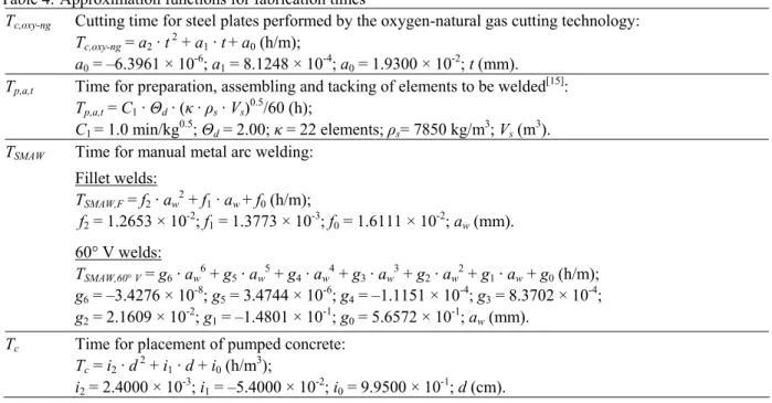
of the manufacturing cost optimization of the simply supported composite I beam floor system. The considered composite I beam floor system is 30 m long, subjected to combined effects of the self-weight and the variable imposed load of 5.0 kN/m2, see Fig. 3.
L = 30.0 m
q = 5.0 kN/m2
Fig. 3: Variable imposed load and the span of the composite I beam floor system
The considered composite floor system is built up of reinforced concrete slab of a constant depth and of doubly-symmetrical welded structural steel sections. Individual steel beams and the concrete slab are connected together by the cylindrical shear studs, welded to the top of the steel section by using the arc stud welder and embedded in the concrete. The base diameter of the stud is 19 mm and the overall height is 100 mm.
Each I beam consists of 6 members which are welded together with full penetration V welds. Single
Author Manuscrip
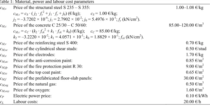
Table 1: Material, power and labour cost parameters
cM,s Price of the structural steel S 235 – S 355: 1.00–1.08 €/kg cM,s = cS · ( j2 · fy2 + j1 · fy + j0) (€/kg); cS = 1.00 €/kg;
j2 = –3.7202 × 10⁻⁴; j1 = 2.7902 × 10⁻²; j0 = 5.4976 × 10⁻¹; fy (kN/cm2).
cM,c Price of the concrete C 25/30 – C 50/60: 85.00–120.00 €/m3 cM,c = cC · (k2 · fck2 + k1 · fck + k0) (€/kg); cC = 85.00 €/kg;
k2 = –3.2220 × 10⁻²; k1 = 4.0571 × 10⁻¹; k0 = 1.8829 × 10⁻¹; fck (kN/cm2).
cM,r Price of the reinforcing steel S 400: 0.70 €/kg
cM,sc Price of the cylindrical shear studs: 0.50 €/stud
cM,e Price of the electrodes: 1.70 €/kg
cM,ac Price of the anti-corrosion paint: 0.85 €/m2
cM,fp Price of the fire protection paint R 30: 9.00 €/m2
cM,tc Price of the top coat paint: 0.65 €/m2
cM,f Price of the prefabricated floor-slab panels: 30.00 €/m2
cM,ng Price of the natural gas: 0.50 €/m3
cM,oxy Price of the oxygen: 1.60 €/m3
cP Electric power price: 0.10 €/kWh
cL Labour costs: 20.00 €/h
Table 2: Fabrication times
Tg Time of the edge grinding of the steel sections to be welded: 33.333 × 10⁻³h/m
Tsw Time for arc stud welding: 2.433 × 10⁻⁴h/stud
Tv Time for consolidation of the concrete: 0.200 h/m2
Tswp Time for stud welding, placing/removal of a ferrule and cleaning: 55.555 × 10⁻⁴h/stud
Tss Time for sand-spraying: 0.050 h/m2
Tac Time for anti-corrosion resistant painting: 0.050 h/m2
Tfp Time for fire protection painting: 0.050 h/m2
Ttc Time for top coat painting: 0.050 h/m2
Tf Time for paneling, leveling, disassembly and cleaning the formwork: 0.300 h/m2 Tr Time for cutting, placing and connecting the reinforcement: 0.024 h/kg
Tcc Time for curing the concrete: 0.200 h/m3
Table 3: Approximation functions for natural gas and oxygen consumption Qng Natural gas consumption:
Qng = b4 · t 4 + b3 · t 3 + b2 · t 2 + b1 · t + b0 (m3/h);
b4 = –8.6803 × 10⁻⁷; b3 = 1.0969 × 10⁻⁴; b2 = –4.9262 × 10⁻³; b1 = 9.1898 × 10⁻²; b0 = 4.1176 × 10⁻¹; t (mm).
Qoxy Oxygen consumption:
Qoxy = c6 · t 6 + c5 · t 5 + c4 · t 4 + c3 · t 3 + c2 · t 2 + c1 · t + c0 (m3/h);
c6 = 1.4266 × 10⁻⁷; c5 = –1.8327 × 10⁻⁵; c4 = 8.8852 × 10⁻⁴; c3 = –2.0047 × 10⁻²; c2 = 2.0634 × 10⁻¹; c1 = –6.3661 × 10⁻¹; c0 = 2.2086; t (mm).
Author Manuscrip
13 Table 4: Approximation functions for fabrication times
Tc,oxy-ng Cutting time for steel plates performed by the oxygen-natural gas cutting technology: Tc,oxy-ng = a2 · t 2 + a1 · t + a0 (h/m);
a0 = –6.3961 × 10⁻⁶; a1 = 8.1248 × 10⁻⁴; a0 = 1.9300 × 10⁻²; t (mm). Tp,a,t Time for preparation, assembling and tacking of elements to be welded[15]:
Tp,a,t = C1 · Θd· (κ· ρs· Vs)0.5/60 (h);
C1 = 1.0 min/kg0.5; Θd = 2.00; κ = 22 elements;ρs= 7850 kg/m3; Vs (m3). TSMAW Time for manual metal arc welding:
Fillet welds:
TSMAW,F = f2 · aw2 + f1 · aw + f0 (h/m);
f2 = 1.2653 × 10⁻²; f1 = 1.3773 × 10⁻³; f0 = 1.6111 × 10⁻²; aw (mm). 60° V welds:
TSMAW,60° V = g6 · aw6 + g5 · aw5 + g4 · aw4 + g3 · aw3 + g2 · aw2 + g1 · aw+ g0 (h/m); g6 = –3.4276 × 10⁻⁸; g5 = 3.4744 × 10⁻⁶; g4 = –1.1151 × 10⁻⁴; g3 = 8.3702 × 10⁻⁴; g2 = 2.1609 × 10⁻²; g1 = –1.4801 × 10⁻¹; g0 = 5.6572 × 10⁻¹; aw (mm).
Tc Time for placement of pumped concrete: Tc = i2 · d 2 + i1 · d + i0 (h/m3);
i2 = 2.4000 × 10⁻³; i1 = –5.4000 × 10⁻²; i0 = 9.9500 × 10⁻¹; d (cm). Table 5: Material, power and technology factors
ρs Steel density: 7850 kg/m3
ρc Concrete density: 2500 kg/m3 EMY Electrode metal yield: 0.60
kp Paint loss factor – painting technique: 0.05 for brush painting ksur Paint loss factor – complexity of the structure: 1.00 for large surfaces kwc Paint loss factor – weather conditions: 1.00 for brush painting nuc Number of useable cycles of the formwork floor-slab panels: 30 kam Factor – allowances to machining time: 1.09
Pgm Power of the grinding machine: 1.10 kW
ηgm Machine power efficiency: 0.85 for the grinding machine I Welding current: 230 A
Isw Stud welding current: 1409 A U Welding voltage: 25 V Usw Stud welding voltage: 20 V
ηw Machine power efficiency: 0.90 for the arc welding machine DR Deposition rate: 3.7 kg/h
Pv Power of the internal vibrator ø48 mm: 3.10 kW
ηv Machine power efficiency: 0.85 for the internal concrete vibrator kd Difficulty factor – working conditions: 1.00 normal conditions
kwp Difficulty factor – welding position: 1.00 for flat position; 1.10 for vertical and overhead position kwd Difficulty factor – welding direction: 1.00 for flat position and vertical welds
kwl Difficulty factor – welding length: 1.00 for long welds; 1.20 for welding length less than 0.50 m kr Difficulty factor – root of the weld: 1.00 without treatment of root; 1.20 with treatment of root kdp Difficulty factor – painting position: 1.00 for horizontal painting; 2.00 for vertical painting krh Difficulty factor – structural height: 1.00 for structural height less than 6 m
kri Difficulty factor – inclination of the concrete slab: 1.00 for horizontal slab
Author Manuscrip
Table 6: Recapitulation of the optimal manufacturing costs Material costs:
CM,s Structural steel S 355 5380.21 €
CM,c Concrete C 30/37 2480.27 €
CM,r Steel-wire mesh reinforcement R–335 S 400 433.01 €
CM,sc Cylindrical shear studs 84.00 €
CM,e Electrodes 41.72 €
CM,ac,fp,tc Anti-corrosion paint, fire protection paint and top coat paint 1417.95 €
CM,f Floor-slab panels 130.80 €
CM,c,ng Natural gas 2.65 €
CM,c,oxy Oxygen 32.66 €
Total material costs: 10003.27 € Power consumption costs:
CP,gm Edge grinding process 0.24 €
CP,w Welding process 2.54 €
CP,sw Arc stud welding process 0.13 €
CP,v Vibrating the concrete 9.54 €
Total power consumption costs: 12.45 € Labour costs:
CL,c,oxy-ng Steel-sheet cutting performed by the oxygen-natural gas technology 112.64 €
CL,g Edge grinding 36.97 €
CL,p,a,t Preparation, assembly and tacking of the elements 205.92 € CL,SMAW Welding process performed by SMAW technology 654.17 €
CL,sw Semi-automatic arc stud welding process 18.67 €
CL,spp Sand-spraying, anti-corrosion, fire resistant and top coat painting 1383.87 € CL,f Panelling, levelling, disassembly and cleaning of the formwork 784.80 €
CL,r Cutting, placing and connecting the reinforcement 277.38 €
CL,c Concreting the reinforced concrete slab 457.80 €
CL,v Consolidating the concrete by internal vibrators 523.20 €
CL,cc Curing the concrete 104.64 €
Total labour costs: 4560.06 €
Total manufacturing costs per 1 composite I beam: 14575.79 €
Total manufacturing costs per m2 of useable surface of the composite floor: 111.44 €/m2
Author Manuscrip
15 member consists of steel plate elements, cut from a structural steel sheet by using the oxygen-natural gas cutting technology. The maximum allowed thickness of steel plate elements is 40 mm. The cuts are executed successively. The costs of scrap are neglected. The beam members are joined by single 60º V welds. Both flanges and the web are connected together with a fillet welds. The vertical stiffeners are also joined with a fillet welds. After the steel I beam is composed, its steel surface is manually sand-sprayed and brushed over with a single coat of anti-corrosion paint, two coats of fire protection paint (R30) and a top coat.
The panelling of the concrete slab takes place in such a manner that the fully prefabricated formwork is assembled by skilled workers. It is assumed that formwork floor-slab panels can be used 30 times before they have to be replaced by new ones. The concrete slab is designed separately as a one-way spanning slab of constant depth, running continuously over the steel sections. The concrete slab is thus reinforced with the one-way spanning wire mesh reinforcement produced from steel S 400. The placement and consolidation of concrete is achieved by using a concrete pump and internal vibrators. The concrete is cured by ponding the water for 3 days after the placement. The input data for the cost optimization of composite I beam floor system includes:
1. Material, power and labour cost parameters, listed in Table 1.
2. Fabrication times, listed in Table 2.
3. Approximation functions for natural gas and oxygen consumption, listed in Table 3.
4. Approximation functions for fabrication times, listed in Table 4.
5. Material, power and technology factors, listed in Table 5.
The optimization was performed in order to find the optimal cross-section dimensions, the optimal concrete strength and the optimal steel grade of the composite I beam floor system with respect to the minimum of manufacturing costs, subjected to the design constraints, defined according to the Eurocodes.
The developed optimization model COMBOPT was used. Six different concrete strengths from 25 to 50 MPa (C 25/30 to C 50/60) and three various structural
steels S 235, S 275 and S 355 were included in the optimization. While the material costs of the structural steel S 235 and the concrete C 25/30 were considered to be the input data, the costs of higher steel grades and concrete strengths were calculated by means of the approximation functions throughout the optimization process.
The optimization was carried out in two successive steps. The first step denotes the ordinary NLP optimization. At this level, the continuous variables (dimensions, materials) were calculated inside their upper and lower bounds. The calculated structure was fully exploited considering either ultimate or serviceability limit state conditions. In the second step, the calculation was repeated/checked for the fixed variables rounded up, from in the first step obtained continuous values, to their nearest upper standard/discrete values. CONOPT2 (Generalized reduced-gradient method)[16] was used for the NLP optimization.
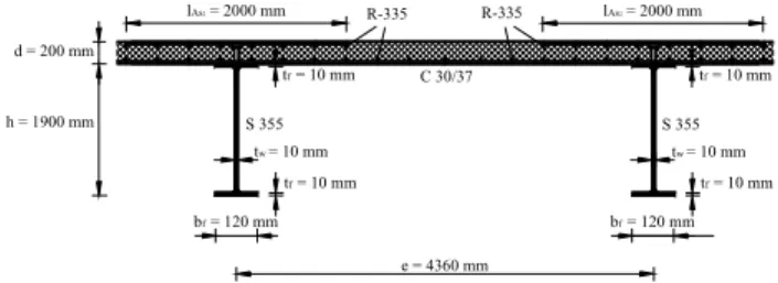
The optimal structural design of the considered composite I beam floor system was obtained in the second step of the optimization, see Fig. 4. The obtained minimum of the manufacturing costs was found to be 14575.79 € per single composite I beam or 111.44 € per m2 of the useable surface of the composite floor system. The optimal results include the steel grade, the concrete strength, the intermediate distance between I beams, the composite floor cross-section dimensions and the cross-section area of the steel-wire mesh reinforcement.
h = 1900 mm
C 30/37 tf = 10 mm tf = 10 mm
tf = 10 mm bf = 120 mm
e = 4360 mm tw = 10 mm
S 355
tf = 10 mm bf = 120 mm
tw = 10 mm S 355 d = 200 mm
lAs2 = 2000 mm R-335 R-335 lAs2 = 2000 mm
Fig. 4: Optimal cross-section design of the composite I beam floor system
The example also shows the distribution of the obtained minimal manufacturing costs of the composite I beam floor system for the considered economical data. The material costs represent 68.6%, the labour costs 31.3% and the power consumption costs 0.1% of the
Author Manuscrip
obtained minimal manufacturing costs, see Table 6 and Fig. 5. The example indicates that the power consumption costs may be neglected at the estimation process of the self-manufacturing costs.
Total labour costs 31,29%
Total power costs 0,09%
Total material costs 68,63%
Panelling 6,28% Steel-wire
mesh reinforcement
4,87%
Concrete 17,02%
Steel surface protection
19,22%
Concrete placement and treatment
7,51%
Structural steel 36,91%
Welding 6,20% Shear studs
0,71%
Sheet-steel cutting 1,27%
Fig. 5: The distribution of the manufacturing costs of the composite I beam floor system
Table 6: Recapitulation of the optimal manufacturing costs
CONCLUSIONS
The paper presents the cost optimization of the composite I beam floor system. The composite I beam floor system is consisted of a reinforced concrete slab of constant depth and doubly-symmetrical welded steel I beams. The optimization was performed by the nonlinear programming approach, NLP. A NLP optimization model for composite I beam floor system was thus developed. The objective function of the structure’s manufacturing costs was subjected to a rigorous system of design, load, resistance and deflections (in)equality constraints, defined in accordance with Eurocode 4 to satisfied both the ultimate and the serviceability limit states.
An accurate objective function of the manufacturing material, power and labour costs was defined for the optimization. The material costs included the structural steel, the concrete, the reinforcement, the shear connectors, the electrodes, the anti-corrosion, fire protection and top coat painting, the formwork
floor-slab panels, the natural gas and oxygen consumption. The defined power consumption costs comprised the costs of edge grinding, welding, stud welding and vibrating the concrete. The labour costs included the costs of sheet-steel cutting, edge grinding, preparation, assembling and tacking, welding, welding of shear studs, steel surface preparation and protection, placing the formwork, cutting, placing and connecting the reinforcement, concreting, consolidating and curing the concrete.
Furthermore, the objective function also includes the fabrication times, electrical power and material consumption which provides the engineer with details about the manufacturing costs distribution of the obtained optimal design. Since the cost function is detailed and formulated in an open manner, it can be easily adopted and used for any specific data in different economical and technological conditions. The numerical example presented at the end of the paper shows the applicability of the proposed approach.
ACKNOWLEDGEMENTS
This research was supported by the Slovenian Research Agency through research programme P2-0129 “Development, modelling and optimization of structures and processes in civil engineering and traffic”.
REFERENCES
1. Surtees, J.O. and D. Tordoff, 1977. Optimum design of composite box girder bridge structures. Proceedings of the Institution of Civil Engineers (London), Part 1 – Design & Construction, 63(2): 181–194.
2. Bhatti, M.A., 1996. Optimum cost design of partially composite steel beams using LRFD. Eng. J., 33(1): 18–29.
3. Cohn, M.Z. and J.J. Werner, 1996. Optimization of composite highway bridge systems. Proceedings of the 1996 12th Conference on Analysis and Computation, pp. 135–146.
4. Kravanja, S. and S. Šilih, 2001. The MINLP optimization of composite I-beams. Proceedings of the Sixth International Conference on Computer Aided Optimum Design of Structures, pp. 401– 407.
5. Long, W., M.S. Troitsky and Z.A. Zielinski, 1999. Optimum design of cable stayed bridges. Struct. Eng. Mech., 7(3): 241–257.
Author Manuscrip
17 6. Adeli, H. and H. Kim, 2001. Cost optimization of
welded of composite floors using neural dynamics model. Commun Numer. Methods Eng., 17(11): 771–787.
7. Kravanja, S. and S. Šilih, 2003. Optimization based comparison between composite I beams and composite trusses, J. Constr. Steel Res., 59(5): 609–625.
8. Eurocode 1, 1995. Basis of design and actions on structures, European Committee for Standardization, Brussels.
9. Eurocode 2, 1992. Design of concrete structures, European Committee for Standardization, Brussels.
10. Eurocode 3, 1995. Design of steel structures, European Committee for Standardization, Brussels.
11. Eurocode 4, 1992. Design of composite structures, European Committee for Standardization, Brussels.
12. Brooke, A., D. Kendrick and A. Meeraus, 1988. GAMS - A User’s Guide, Scientific Press, Redwood City, CA.
13. Klanšek, U. and S. Kravanja, 2006. Cost estimation, optimization and competitiveness of different composite floor systems–Part 1: Self-manufacturing cost estimation of composite and steel structures. J. Constr. Steel Res. 62(5): 434– 448.
14. Robert C. Creese, M. Adithan, B.S. Pabla, 1992. Estimating and costing for the metal manufacturing industries. New York: Marcel Dekker.
15. Jármai, K. and J. Farkas, 1999. Cost calculation and optimization of welded steel structures. J. Constr. Steel Res., 50(2): 115–135.
16. Drud, A.S., 1994. CONOPT – A Large-Scale GRG Code. ORSA J. Comput., 6(2): 207–216.